C-3568BQ Overview
Chapter 1 Product Overview
The C-3568BQ V1.0 core board adopts Rockchip RK3568B2 (Cortex-A55x4) quad-core processor, equipped with Android11 system, with a main frequency of up to 2.0GHz, super performance, rich interfaces, and first-class running points and decoding. It is your new choice for human-computer interaction and industrial control projects.
1.1 Scope of application
C-3568BQ V1.0 is a high-performance, low-power core board based on Rockchip RK3568B2 processor. It is widely used in smart display terminal products, video terminal products, and industrial automation terminal products, such as advertising machines, digital signage, smart self-service terminals, smart retail terminals, O2O smart devices, industrial control hosts, robotic equipment, etc.
1.2 Product Features
- Rich display interfaces, integrating HDMI/LVDS/MIPI/EDP and other display interfaces, supporting multi-screen display.
- It uses 4 groups of 80-pin BTB interfaces to bring out all pin functions, making it convenient and flexible to expand the design.
- It integrates PCIe3.0, dual-channel GMAC, SDIO, I2C, I2S, PWM, UART, and GPIO interfaces to meet the requirements of various peripherals on the market.
- Support dual screen display. LVDS can support a maximum resolution of 1920 1200, and EDP can support a maximum resolution of 2560 1600.
- It comes with a deep neural network unit (NPU) with a performance of 1.0 TOPS, which can meet the needs of deep learning projects.
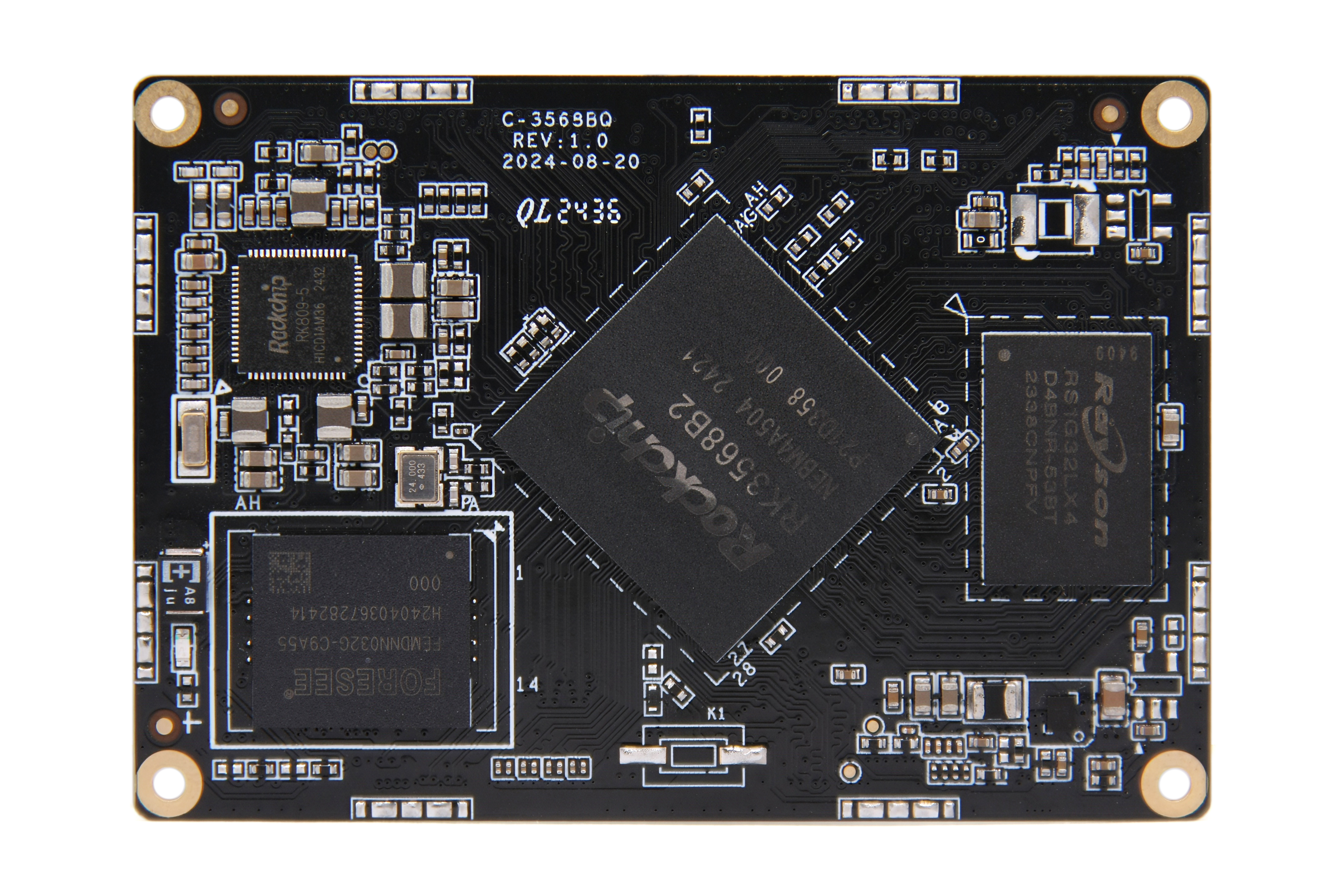
1.3 Appearance and Interface Diagram
front:
back:
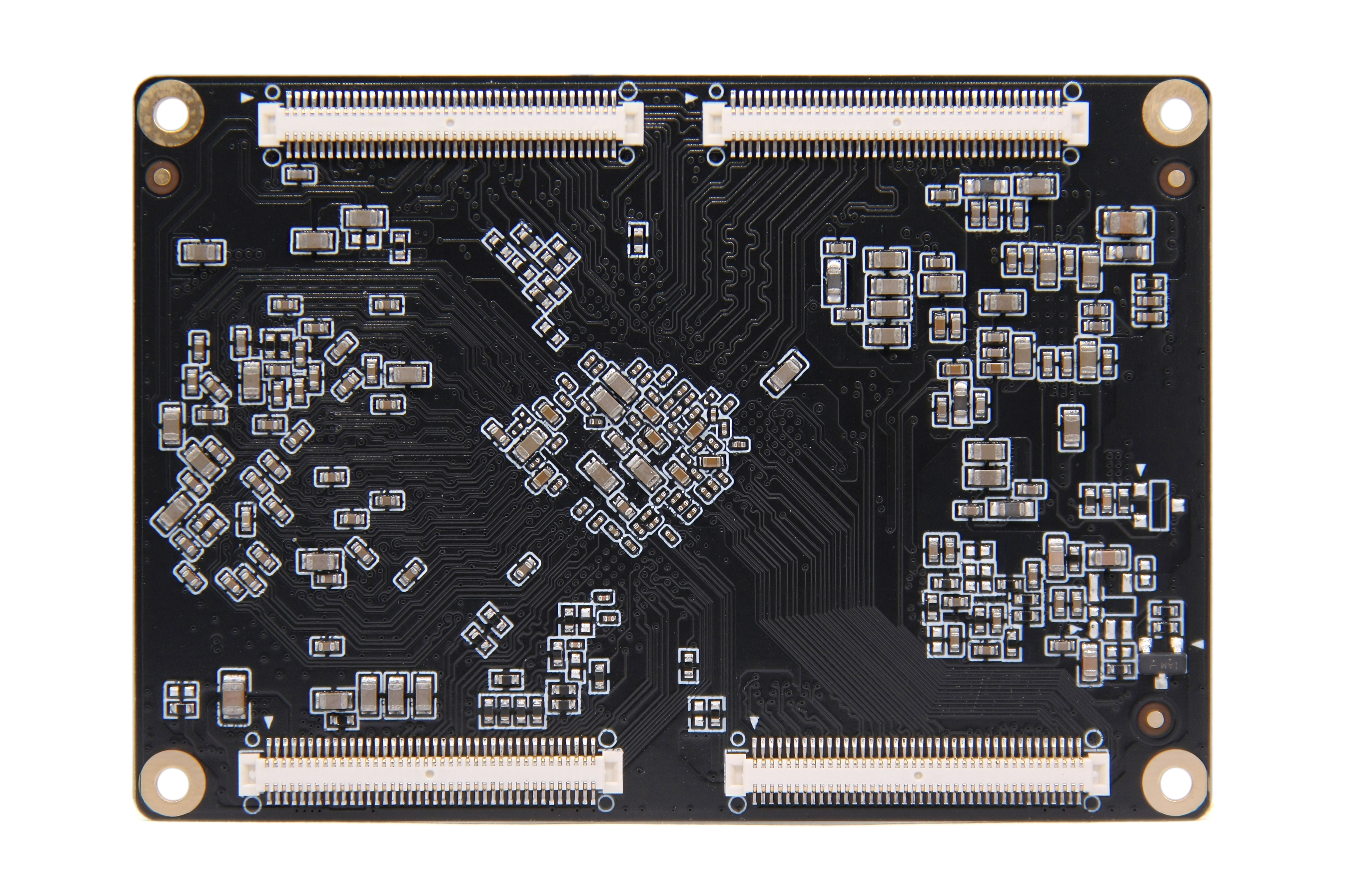
Photo Statement
The above photos were taken from a batch of boards produced by our company. Due to the continuous maintenance of the products, the boards actually shipped may not be consistent with the photos.
Chapter 2 Basic Function List
| Function | Describe |
|---|---|
| Board size | 65*45mm |
| CPU | RK3568B2, quad-core (Cortex-A55x4), maximum frequency 2.0GHz |
| operating system | Harmony OS/ Android 11.0 |
| Memory | Supports 4GB LPDDR4 memory |
| store | Supports 32GB, 64GB and 128GB eMMC storage options |
| show | 1 HDMI, supports a maximum resolution of 1080P@60Hz 1 MIPI, supports a maximum resolution of 1080P@60Hz 1 eDP, supports a maximum resolution of 2560*1600 |
| Connectivity | 2 built-in Gigabit Ethernet MAC MAC 1 PCIe3.0 X2 lane RC 1 PCIe2.0 X1 lane RC Up to 3 UARTs Up to 4 I2Cs Up to 1 SPI Up to 2 SDIOs |
| Board-to-Board Connectors | 80P 0.5mm pitch B2B connector X4 |
| Operating temperature | -10°C to 60°C |
Chapter 3 PCB Size and Interface Layout
3.1 PCB Dimensions
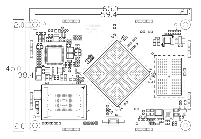
- PCB: 8 layers, thickness 1.6mm
- PCBA: L * W=65mm*45mm,MAX H=7.0(??)+/-0.3mm
- Screw hole specifications: M2 x 4
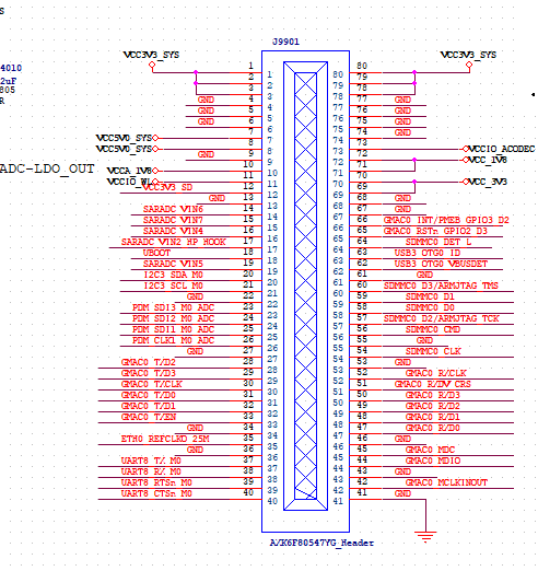
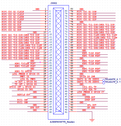
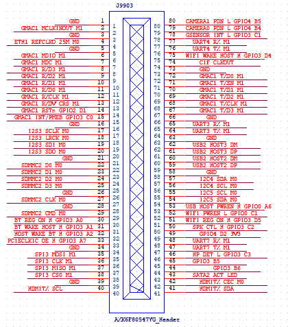
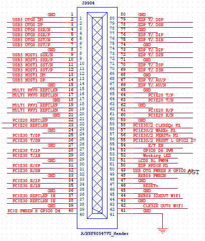
3.2 Interface parameter description
Image annotation: The circle on the socket interface image  indicates the first pin.
BTB interface (80pin/0.5mmX4)
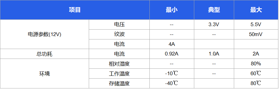
Chapter 4 Electrical Performance
Copyright Notice
This user manual, including but not limited to all the information contained therein, is protected by copyright law. Without the permission of ShiMetaPi, no imitation, copying, excerpting, translating, distributing or other use is allowed.
Disclaimer
The ownership and intellectual property rights of third-party product names or contents mentioned in this user manual belong to the respective product or content owners and are protected by current intellectual property laws and international treaties.