SC-3568HA Overview
Chapter 1 Product Overview
1.1 Scope of Application
Development Kit 3568HA is a high-performance AIoT HarmonyOS development kit equipped with a 5.5-inch HD display, touchscreen, 8MP camera, and compatibility with multiple external interface devices. Built around the RK3568 HarmonyOS motherboard and powered by the OpenHarmony operating system, it delivers exceptional 1TOPS@INT8 computing performance. The kit supports diverse IoT systems, voice systems, and services, featuring rich expansion interfaces to meet versatile product development needs. It comes with comprehensive tutorials, technical documentation, and application demos, enabling rapid deployment in fields such as IoT smart connectivity, intelligent speech recognition, human-machine interfaces (HMIs), industrial control, and smart robotics.
1.2 Appearance and Interfaces Diagram
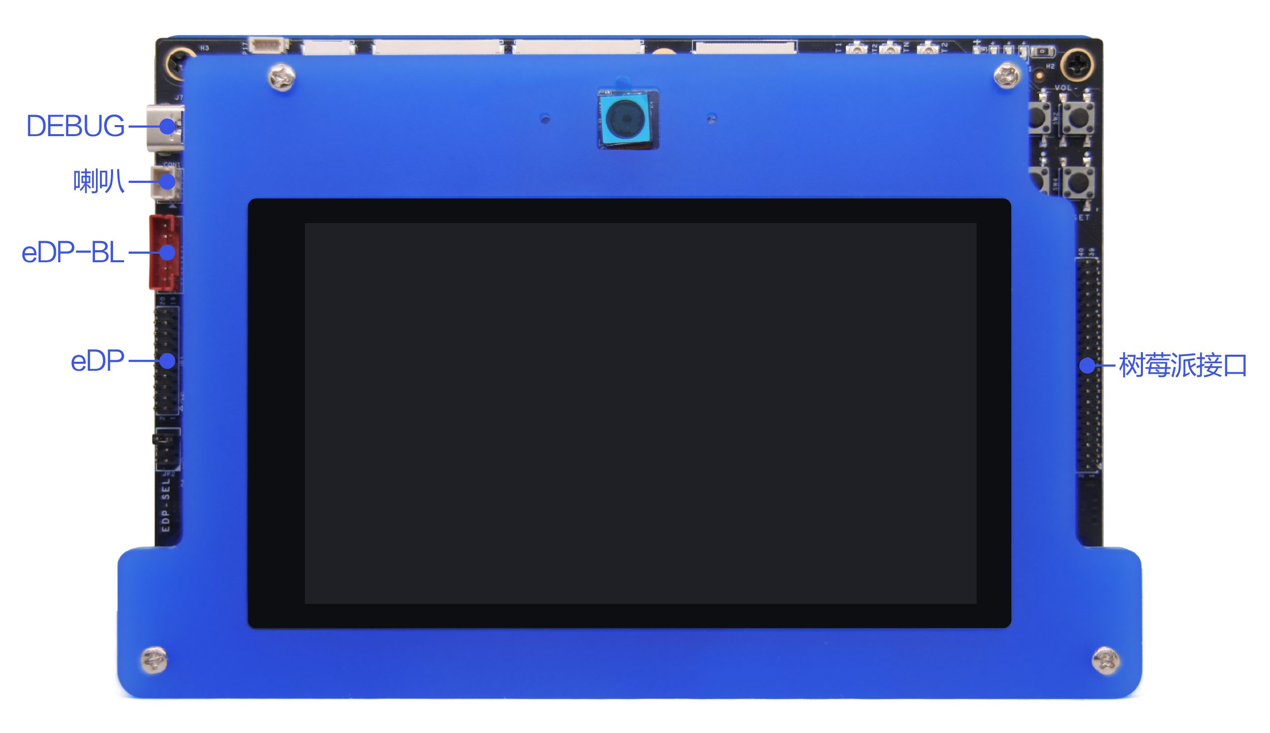
Front Panel:
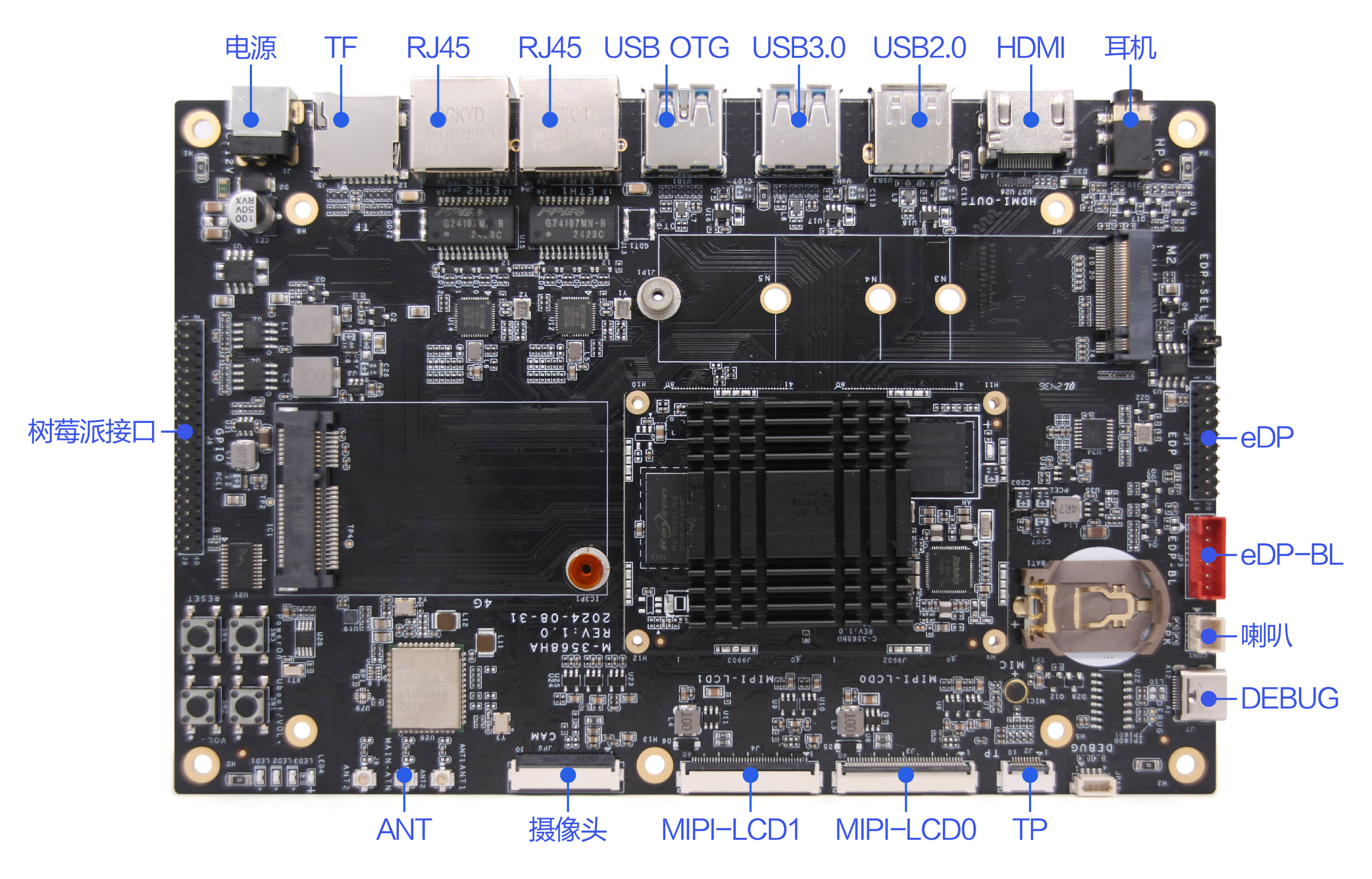
Rear Panel:
Front View:
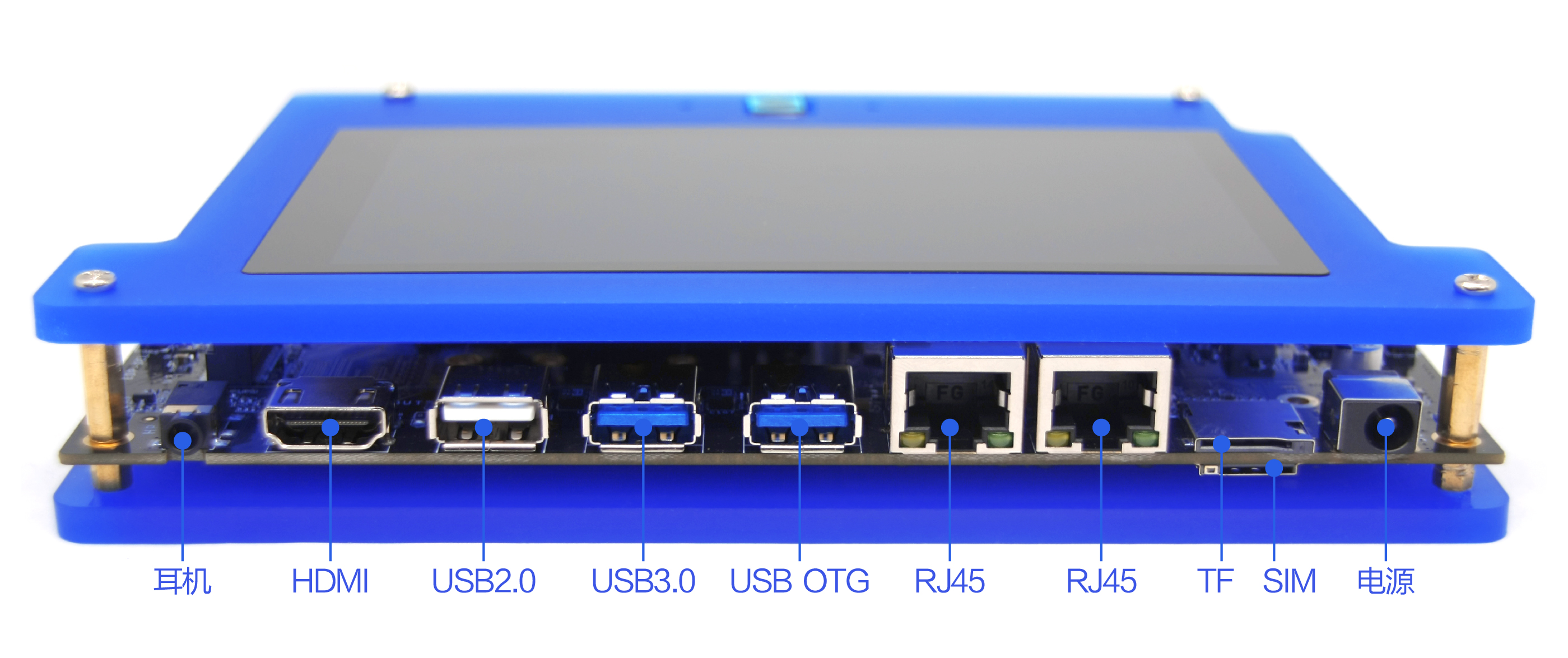
Image Disclaimer
The photographs above are taken from a specific batch of boards produced by our company. Due to continuous product improvements, the actual shipped boards may differ slightly from the images shown.
Chapter 2 Basic Function List
| Function | Description |
|---|---|
| Board Dimensions | 180*120mm |
| CPU Specifications | Quad-core 64-bit Cortex-A55 @ 2.0GHz (max) |
| GPU Specifications | ARM G52 2EE (supports OpenGL ES 1.1/2.0/3.2, OpenCL 2.0, Vulkan 1.1) with integrated high-performance 2D acceleration. |
| NPU Specifications | 1 TOPS computing power (AI acceleration) |
| **OS ** | Harmony |
| Memory / Storage | Standard 4GB / 32GB |
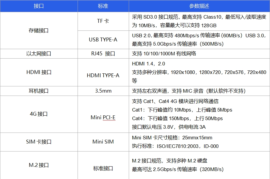
| HDMI Output | 1 port, standard Type-A female connector, supports up to 4Kx2K@60Hz resolution |
| MIPI Output | 1 port, directly drives MIPI interface LCD screens at various resolutions (max 1920x1080) |
| MIPI Input | 1 port, supports 8MP camera input |
| eDP Output | 1 port, directly drives eDP interface LCD screens (tested up to 1920x1080, RK official test max 2650x1600) |
| Audio I/O | Speaker output (supports mono 1.3W) |
| Headphone Output | Supports 3/4-pole headphone jack |
| USB Ports | 1x USB3.0 OTG, 2x USB HOST |
| Serial Port | 1x TTL |
| I2C Interface | 1x I2C port for touchscreen/peripherals |
| Raspberry Pi Header | 1x 2x20PIN header (2.0mm pitch) |
| Networking | 1. 10/100/1000M adaptive Ethernet,2. Built-in Wi-Fi + Bluetooth,3. MINI PCI-E slot (supports 4G LTE, no voice calls) |
| Storage Expansion | USB flash drive, microSD card, M.2 SSD support |
| RTC | Low-power real-time clock support |
| System Upgrade | Local USB firmware update |
| BOM | Dev board1, 5.5" MIPI screen1, MIPI camera1, USB3.0 cable1, USB-C adapter1, power adapter1, Ethernet cable*1 |
Chapter 3 PCB Dimensions and Interface Layout
3.1 PCB Dimensional Drawing
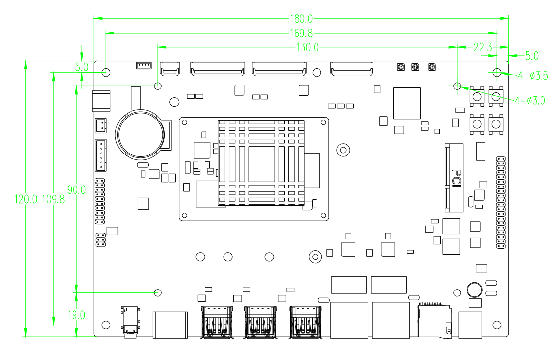
PCB: Board Thickness 1.6mm
PCBA: Dimensions L × W = 180mm × 120mm
Screw Hole Specification: Diameter 3.2mm x Depth 5mm
Notes
1.Thermal Design
2.Actual product dimensions shall prevail.
3.2 Interface Parameters Specification
Image Annotation Guide: :The circled area in the socket interface image labeled indicates Pin 1, and the red housing's
 image similarly denotes the first pin.
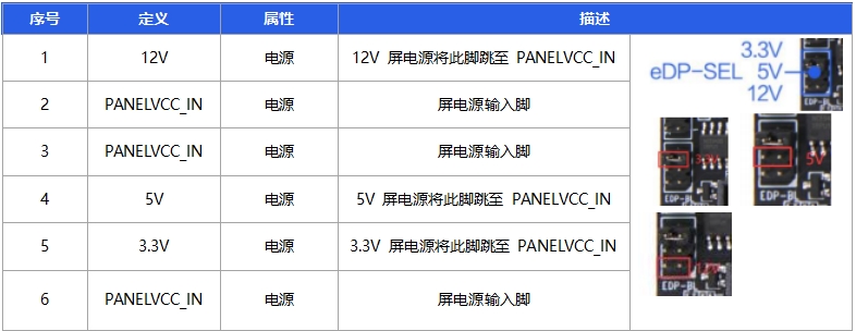
3.2.1 Backlight Control Interface (6-pin / 2.0mm pitch dual row)
Function Description:
The motherboard comes standard with one integrated backlight adjustment/control interface, specifically configured as the eDP (Embedded DisplayPort) backlight control interface.
Electrical Specifications

Notes
1.The 12V power supply in this socket must only be used as a backlight power output and
must never be used as a power input to the system.

2.The eDP backlight connector defaults to PWM dimming. Please select the appropriate
dimming method according to the datasheet specifications of the chosen display panel.

3.The ADJ and PWM modes can be switched by hardware modification. For any modification
requirements, please contact the Field Application Engineer (FAE) for assistance.

4.Due to limited trace width in the motherboard's power circuitry, the design typically
only accounts for the motherboard's own power consumption. When using displays larger
than 19 inches or with power consumption exceeding 15W, obtain backlight power from an
external power source to prevent system instability.
3.2.2 EDP Display Interface (10×2-pin dual row / 2.0mm pitch)
Function Description:
This interface is a standard eDP display connector, featuring a 10×2-pin dual-row configuration with 2.0mm pitch.
Electrical Specifications
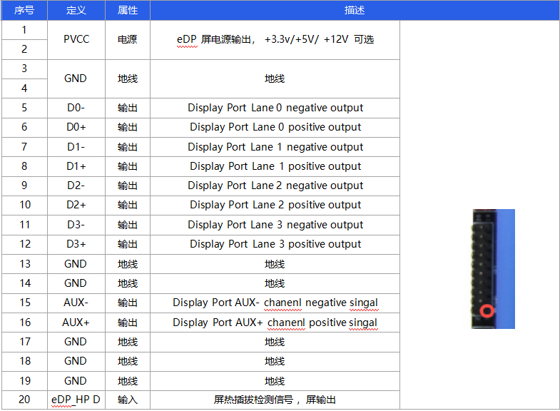
The display power voltage can be adjusted via the eDP-SEL socket by configuring jumper caps, allowing selection of 3.3V/5V/12V display power supply options.
Electrical Specifications
Notes
1.Please verify that the power supply voltage specified in the display datasheet is
correct, and ensure that the corresponding power supply on the board can meet the
display's maximum operating current requirements.

2.Use a multimeter to confirm that the power supply selected via the jumper caps is
correctly configured.

3.Before connecting, ensure the electrical definitions of the wire sequence match.
Power on the system only after the display is fully connected, and never hot-plug/
unplug while the system is operational.
3.2.3 I2C Interface (10-pin / 0.5mm pitch)
Function Description:
The board supports connection to TP displays with I2C interface compatibility.
Electrical Specifications

Notes
1.The board supports connection to TP displays with I2C interface compatibility. Before
connecting, please verify whether the touchscreen interface is I2C or USB.

2.The I2C, RST, and INT signal levels in this interface operate at 3.3V. If connecting a
1.8V touchscreen, proper voltage level conversion must be implemented.

3.Before connecting, ensure the electrical definitions of the wire sequence match. Power
on the system only after the touchscreen is fully connected, and never hot-plug/unplug
while the system is operational.
3.2.4 MIPI Interface (40-pin / 0.5mm pitch dual row)
Function Description:
The board supports connection to MIPI displays.
Electrical Specifications

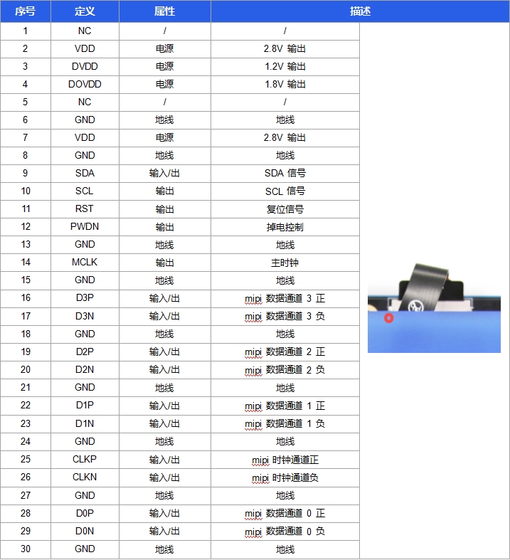
3.2.5 MIPI Camera Interface (30-pin / 0.5mm pitch single row)
Function Description:
The board supports 1-channel MIPI camera input. The board provides default support for GC8034 sensor camera.
MIPI Camera Connector Electrical Definitions Are as Follows:
Notes
1.Maximum supported resolution: 4096×2304.

2.Stereo MIPI camera modules are NOT supported.

3.Signal levels for I2C and RST interfaces are 1.8V. For modules with 3.3V signal levels,
proper level conversion must be implemented before connection.

4.Verify electrical definitions of wire sequences match prior to connection. Power up the
module ONLY after secure connection. Hot-plugging (connecting/disconnecting under power)
is STRICTLY PROHIBITED.
3.2.6 Speaker Interface (2-pin / 2.0mm pitch)
Function Description:
This interface supports connection to an external speaker.
Electrical Specifications
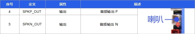
Notes
1.This interface is designed for single speaker connection.

2.Before powering on, ensure the speaker is securely connected. Hot-plugging (connecting/
disconnecting under power) is STRICTLY PROHIBITED.

3.Default output power of the interface is 8Ω/1.3W. When using a 4Ω speaker, reduce the
power by half to avoid overload.
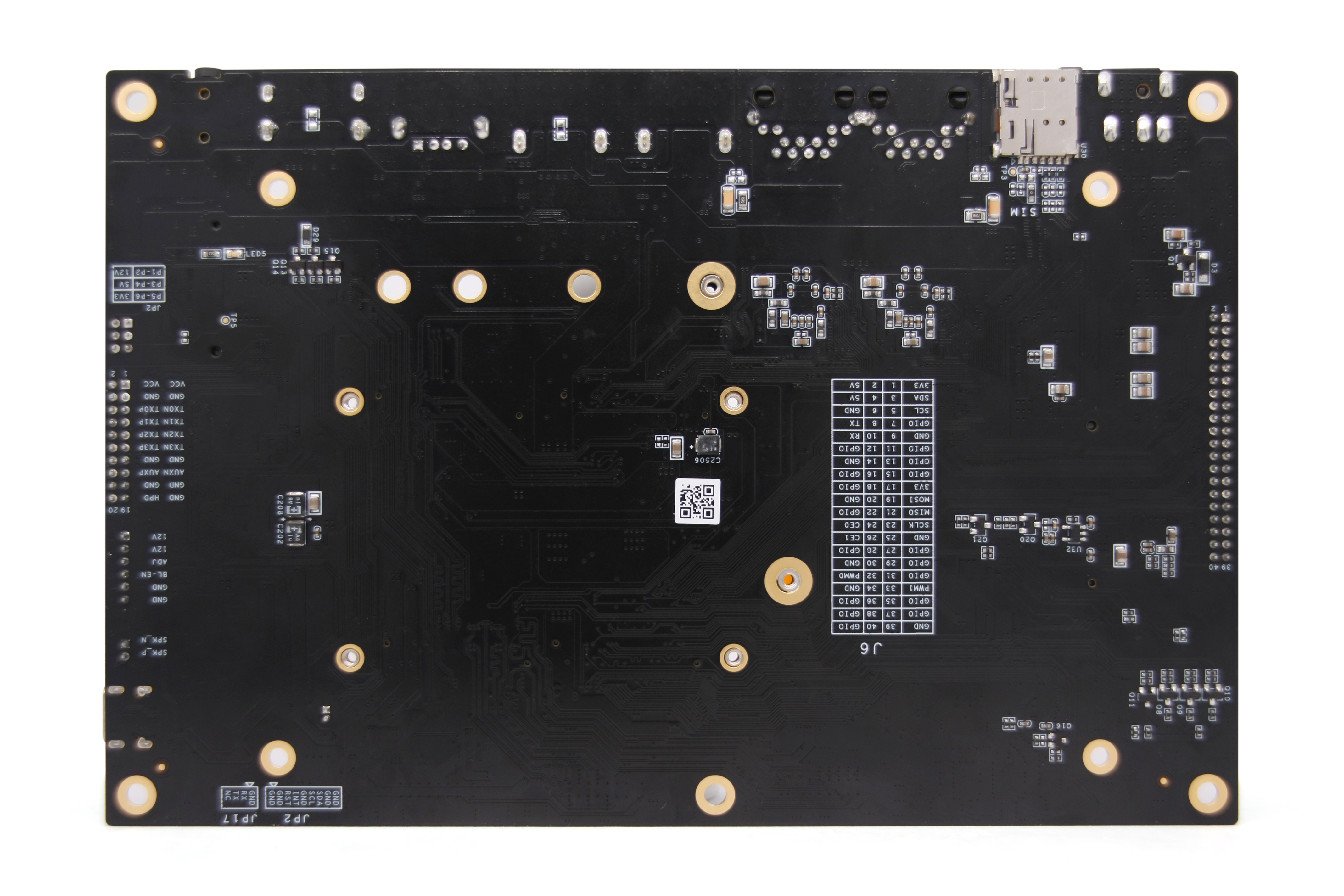
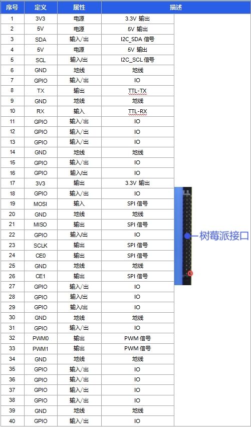
3.2.7 GPIO Interface (20×2-pin / 2.0mm pitch)
Function Description:
This board supports a wide range of peripherals, including most Raspberry Pi-compatible accessories.
Electrical Specifications
3.3 Other Standard Interfaces and Functionalities
Chapter 4 Electrical Characteristics
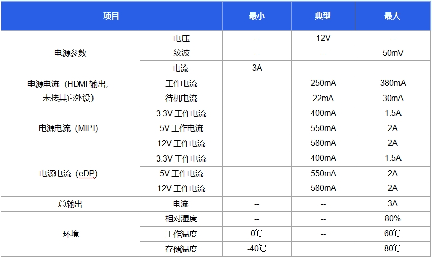
Notes
1.When connecting an eDP screen, ensure the correct operating voltage (3.3V, 5V, or 12V)
is selected to prevent damage to the screen.

2.When connecting an eDP screen, the board's total operating current and standby current
depend on the connected screen, and specific values are not listed individually in the
table above.
Chapter 5 Minimum Test Items for Complete Unit
Description:

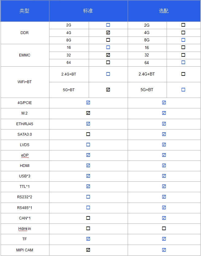
Chapter 6 Configurable Parameters Table (Key Differences)
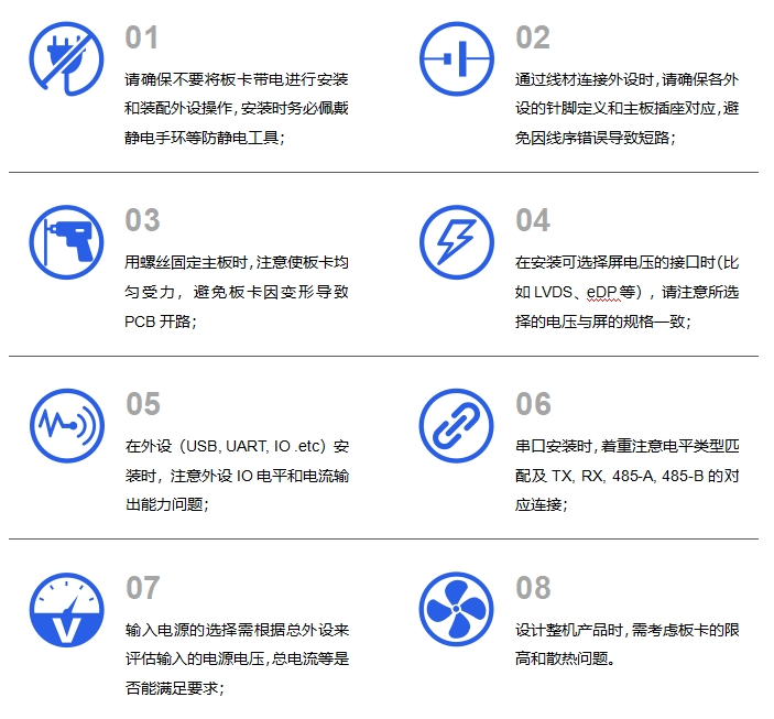
Chapter 7 Usage Precautions (Mandatory Review)
Copyright Notice
This user manual, including but not limited to all information contained herein, is protected under applicable copyright laws. No reproduction, copying, extraction, translation, distribution, or any other form of utilization is permitted without prior written authorization from ShiMetaPi.
Disclaimer
All third-party product names, content, or materials referenced in this user manual are owned by their respective holders, and all associated intellectual property rights are protected under applicable laws and international treaties related to intellectual property.