C-3588LQ Introduction
Chapter 1 Product Overview
The C-3588LQ core board adopts RockChip RK3588 octa-core (4×Cortex-A76+4×Cortex-A55) 64-bit super CPU, built-in 6Tops independent NPU, 8nm advanced manufacturing process, and the main frequency is up to 2.4GHz. It adopts quad-core Mali-G610 MP4 GPU, supports up to 8K@60fps H.265/VP9 video decoding and 8K@30fps H.265/H.264 video encoding, supports the same encoding and decoding, and can achieve up to 32 channels of 1080P@30fps decoding and 16 channels of 1080P@30fps encoding; powerful video encoding and decoding capabilities can make the picture high-definition and more delicate. With stronger performance, faster speed and richer interfaces, it is your best choice for human-computer interaction, smart terminals and industrial control projects.
1.1 Scope of application
The C-3588LQ core board is based on the Rockchip RK3588 platform, with ultra-high floating-point AI processing capabilities, supports multi-channel video and image intelligent analysis, industrial-grade configuration, dustproof, shockproof, and high temperature resistant, and can easily adapt to harsh deployment environments. It is lightweight and can adapt to various terminal forms. It has a wealth of expansion interfaces and can be widely used in smart cities, security, retail, robots, industrial Internet, live broadcast machines, Arm computers, smart displays, edge computing and AIoT solutions, Arm servers, high-performance tablets, and multiple applications that require multiple cameras and displays. Artificial intelligence terminal fields.
1.2 Product Features
- The core board adopts LGA package and is small in size;
- All pins are brought out;
- Rich expansion interfaces;
- Supports Android and Linux systems, provides system call interface API reference code, and perfectly supports customer upper-level application APP development.
1.3 Appearance and Interface Diagram
front:
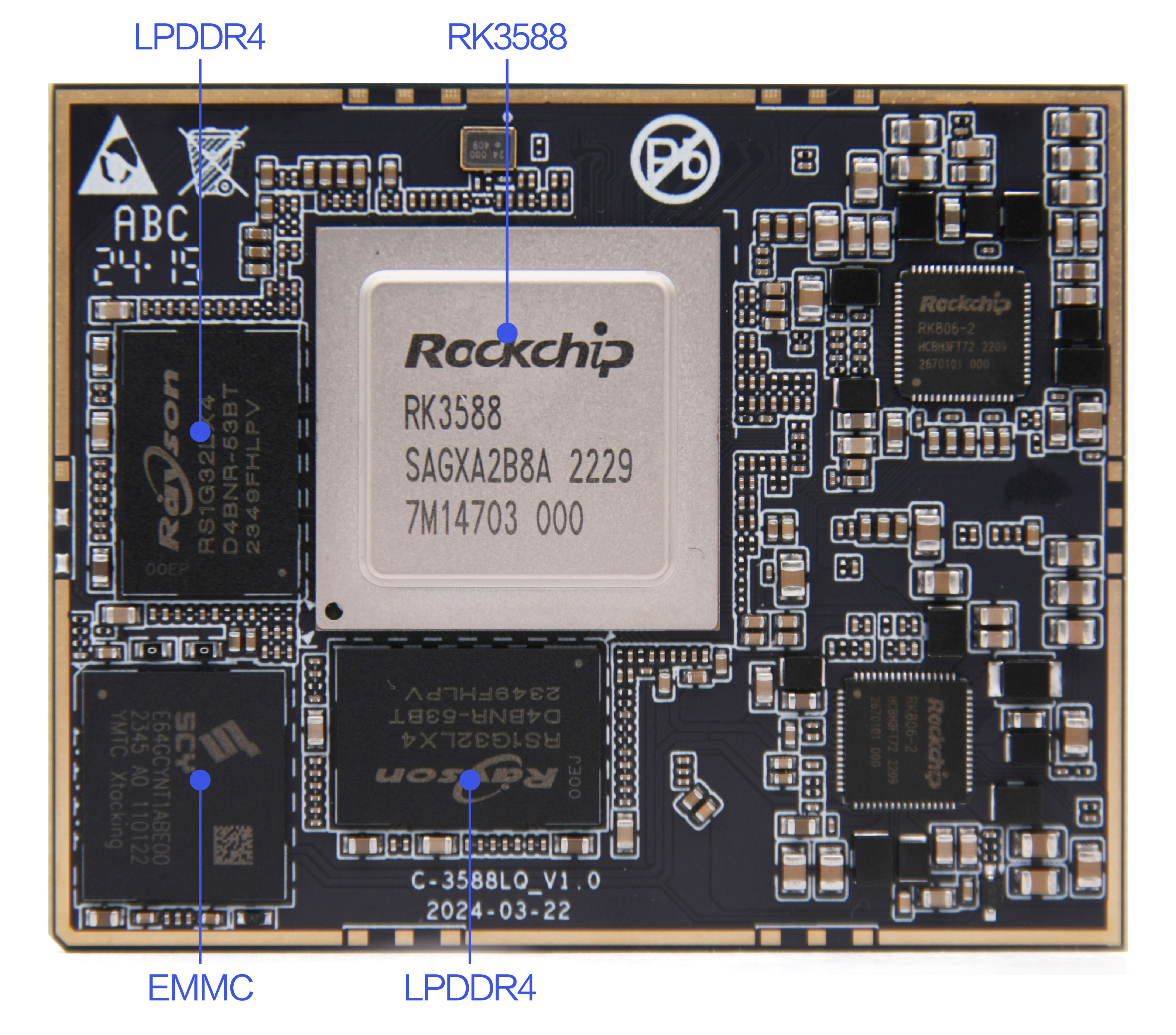
back:
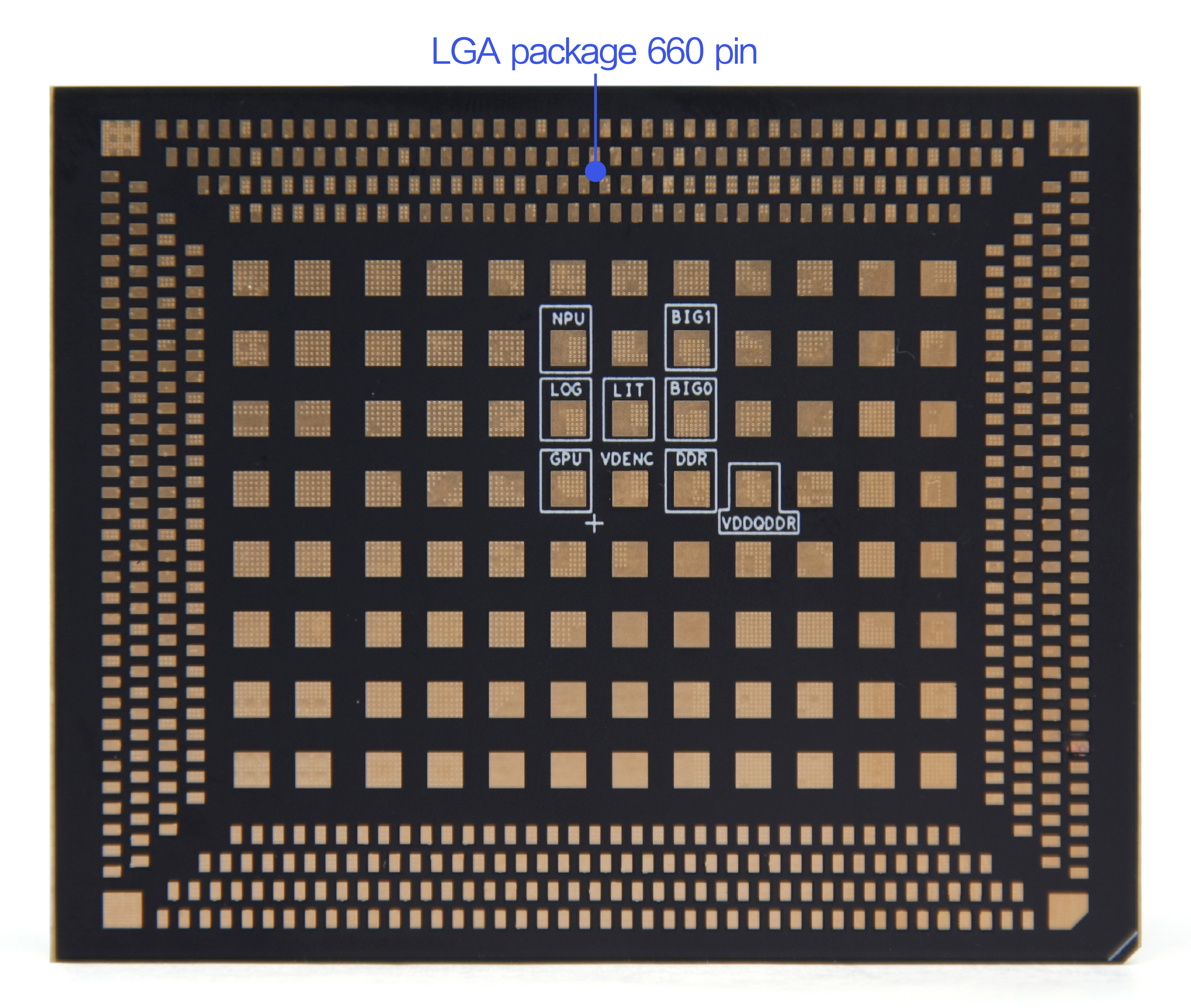
Photo Statement
The above photos were taken from a batch of boards produced by our company. Due to the continuous maintenance of the products, the boards actually shipped may not be consistent with the photos.
Chapter 2 Basic Function List
| Function | Describe |
|---|---|
| Core board size | 62*50mm |
| CPU | RK3588, octa-core 64-bit (4 Cortex-A76+4 Cortex-A55), up to 2.4GHz |
| GPU | ARM Mali-G610 MP4 quad-core high-performance GPU, supports OpenGL ES3.2 / OpenCL 2.2 / Vulkan1.1, 450 GFLOPS |
| NPU | The computing power is up to 6TOPS (INT8), supporting INT4/INT8/INT16 mixed operations, and can realize network model conversion based on TensorFlow/MXNet/PyTorch/Caffe and other series frameworks |
| ISP | Integrated 48MP ISP with HDR&3DNR |
| VPU / Codec | Hard decoding: 8K@60fps H.265/VP9/AVS2, 8K@30fps H.264 AVC/MVC, 4K@60fps AV1, 1080P@60fps MPEG-2/-1/VC-1/VP8 Hard encoding: 8K@30fps H.265/H.264 |
| Memory | LPDDR4/4X, standard 8GB, optional 4GB/16GB, configurable up to 32GB |
| storage | EMMC5.1, standard 64GB, optional 32GB/128GB/256GB |
| power supply | 4V/5A (±5%) |
| operating system | Android 12 / Ubuntu22 |
| interface | LGA package, 660 pins |
| Video Output | 2-way HDMI 2.1 TX/eDP TX (HDMI and eDP multiplexed interfaces, cannot be used at the same time, HDMI supports up to 1-way 7680x4320@60Hz output, supports HDCP2.3; supports eDP1.3, up to 4K@60Hz, supports HDCP1.3) 2-way DP1.4a (multiplexed with USB3.1 Gen1, supports 1, 2, 4 lanes; resolution up to 7680 * 4320@30Hz; supports HDCP2.3, HDCP 1.3) 2-way MIPI DSI (supports MIPI DPHY 2.0 or CPHY 1.1, 4K@60Hz; supports - left and right dual MIPI display, supports RGB/YUV format (up to 10bit), 4 lanes maximum rate up to 4.5Gbps) 1-way BT.1120 output (supports RGB format (up to 8bit), data rate up to 150MHz, resolution up to 1920 * 1080@60Hz) |
| Video Input | 4-way MIPI CSI DPHY (DPHY V1.2 (2lanes, 2.5Gbps/lane); 2 2-lanes DPHY can be combined into 1 4-lanes DPHY) 2-way MIPI D/CPHY (MIPI DPHY V1.2 (4lanes, 2.5Gbps/lane); MIPI CPHY V1.1 (3lanes, 2.5Gsps/lane)) 1-way HDMI RX (supports HDMI 2.0 RX (3.4Gbps~6Gbps); supports HDMI 1.4b (250Mbps~3.4Gbps); supports resolution up to 3840x2160@60Hz) 1-way DVP interface (8/10/12/16-bit standard DVP interface, up to 150MHz data input; supports BT.601/BT.656 and BT.1120 VI Interface) |
| Audio | A total of 4 I2S, supporting TX and RX, audio resolution 16~32 bits, sampling rate up to 192KHz), including 2 8-channel I2S and 2 2-channel I2S; 2 SPDIF, supporting 2*16bit audio data storage and supporting dual-phase stereo output; 2 PDM (8 channels), up to 8 channels, audio resolution 16~24 bits, sampling rate up to 192KHz, supporting PDM main receiving mode, and supporting multiple MIC arrays. |
| HOURS | 3-way SATA3.0 and PCIe2.1 multiplexing |
| PCIe | 3-way PCIe2.1 (1Lane), shared with SATA3, only supports RC (Root Comple), and supports up to 5Gbps data rate; 1-way PCIe3.0 (2 2, 1 4, 4 1) 4 combinations: 1 4Lanes / 2 2Lanes / 4 1Lane / (1 2Lanes + 2 1Lane); each channel supports 8Gbps rate; supports RC and EP.。 |
| USB | 2-way USB3.1 OTG (multiplexed with 2-way DP); 1-way USB3.1 HOST (multiplexed with PCIE and SATA); 2-way USB2.0 HOST; 2-way USB2.0 OTG |
| SDIO | 1 SDIO3.0, supports 4-bit data bus widths |
| I2C | 9-way I2C, supporting 7-bit and 10-bit address modes, data transfer rate up to 100k bits/s in standard mode, up to 400k bits/s in fast mode |
| SPI | 5-way SPI, supports serial master and serial slave modes, software configurable |
| UART | 10-channel UART, built-in 2-channel 64-bit FIFO, can be used for TX and RX respectively; support 5-bit, 6-bit, 7-bit, 8-bit serial data transmission and reception, baud rate up to 4Mbps; 10-channel UART supports automatic flow control mode |
| CAN | 3-way CAN 2.0B, supporting CAN standard frame and extended frame transmission and reception |
| PWM | 16-channel PWM, supports up to 16 PWM, supports capture mode |
| ADC | 8-channel ADC, 12-bit single-ended input SAR-ADC, sampling rate up to 1MS/s |
| GPIO | All GPIOs are brought out and can be used for interrupt applications |
Chapter 3 PCB Size and Interface Layout
3.1 PCB Dimensions
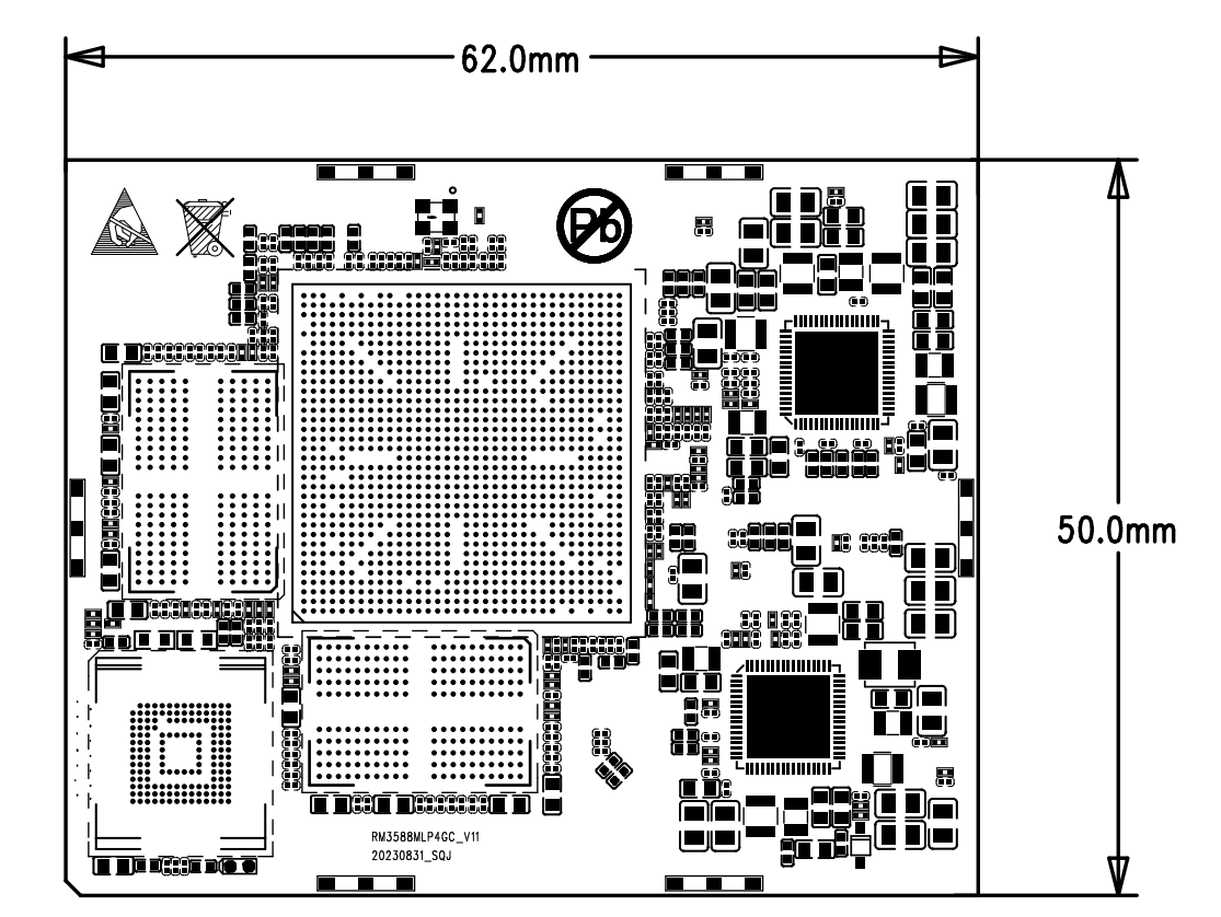
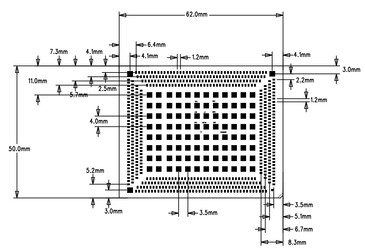
- PCB: 12 layers, thickness 1.6mm
- PCBA: L * W=62mm*50mm,MAX H=3.5+/-0.2mm
Copyright Notice
This user manual, including but not limited to all the information contained therein, is protected by copyright law. Without the permission of ShiMetaPi, no imitation, copying, excerpting, translating, distributing or other use is allowed.
Disclaimer
The ownership and intellectual property rights of third-party product names or contents mentioned in this user manual belong to the respective product or content owners and are protected by current intellectual property laws and international treaties.