07 I2C通讯
1 I2C介绍
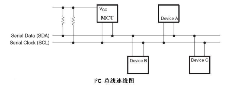
I2C 总线控制器通过串行数据(SDA)线和串行时钟(SCL)线在连接到总线的器件间传递信息。每个器件都有一个唯一的地址识别(无论是微控制器——MCU、LCD 驱动器、存储器或键盘接口),而且都可以作为一个发送器或接收器(由器件的功能决定)。
关于详细的I2C介绍请参考:
2 I2C板卡接口
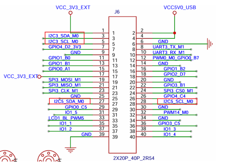
板子的引脚一共引出了2组I2C接口,分别是i2c-3,i2c-5。
3 I2C使用---命令行的方法
3.1 I2C设备树配置
下面,我们根据设备树章节的介绍,来解析一下I2C3和I2C5的设备树配置。
提示
下文的文件路径:out/kernel/src_tmp/linux-5.10/arch/arm64/boot/dts/rockchip/需要先编译码源。
我们先在 rk3568.dtsi 中找到I2C3和I2C5的基础配置内容如下:
i2c3: i2c@fe5c0000 {
    compatible = "rockchip,rk3399-i2c";
    reg = <0x0 0xfe5c0000 0x0 0x1000>;  // 寄存器地址
    clocks = <&cru CLK_I2C3>, <&cru PCLK_I2C3>;  // 时钟配置
    clock-names = "i2c", "pclk";
    interrupts = <GIC_SPI 49 IRQ_TYPE_LEVEL_HIGH>;  // 中断配置
    pinctrl-names = "default";
    pinctrl-0 = <&i2c3m0_xfer>;  // 引脚复用配置
    #address-cells = <1>;
    #size-cells = <0>;
    status = "disabled";  // 默认禁用
};

i2c5: i2c@fe5e0000 {
    compatible = "rockchip,rk3399-i2c";
    reg = <0x0 0xfe5e0000 0x0 0x1000>;  // 寄存器地址
    clocks = <&cru CLK_I2C5>, <&cru PCLK_I2C5>;  // 时钟配置
    clock-names = "i2c", "pclk";
    interrupts = <GIC_SPI 51 IRQ_TYPE_LEVEL_HIGH>;  // 中断配置
    pinctrl-names = "default";
    pinctrl-0 = <&i2c5m0_xfer>;  // 引脚复用配置
    #address-cells = <1>;
    #size-cells = <0>;
    status = "disabled";  // 默认禁用
};再到到rk3568-pinctrl.dtsi中查看I2C的引脚配置:
i2c3m0_xfer: i2c3m0-xfer {
    rockchip,pins =
        /* i2c3_sclm0 - 时钟线 */
        <1 RK_PA1 1 &pcfg_pull_none_smt>,
        /* i2c3_sdam0 - 数据线 */
        <1 RK_PA0 1 &pcfg_pull_none_smt>;
};

i2c5m0_xfer: i2c5m0-xfer {
    rockchip,pins =
        /* i2c5_sclm0 - 时钟线 */
        <3 RK_PB3 4 &pcfg_pull_none_smt>,
        /* i2c5_sdam0 - 数据线 */
        <3 RK_PB4 4 &pcfg_pull_none_smt>;
};
最后找到板级配置文件查看I2C外设的具体配置
在 rk3568-toybrick.dtsi 中,I2C5被使能并配置了传感器设备:
&i2c5 {
	status = "okay";

	gs_mxc6655xa: gs_mxc6655xa@15 {
		status = "okay";
		compatible = "gs_mxc6655xa";
		pinctrl-names = "default";
		pinctrl-0 = <&mxc6655xa_irq_gpio>;
		reg = <0x15>;
		irq-gpio = <&gpio3 RK_PC1 IRQ_TYPE_LEVEL_LOW>;
		irq_enable = <0>;
		poll_delay_ms = <30>;
		type = <SENSOR_TYPE_ACCEL>;
		power-off-in-suspend = <1>;
		layout = <1>;
	};

    mxc6655xa: mxc6655xa@15 {
		status = "disabled";
		compatible = "gs_mxc6655xa";
		pinctrl-names = "default";
		pinctrl-0 = <&mxc6655xa_irq_gpio>;
		reg = <0x15>;
		irq-gpio = <&gpio3 RK_PC1 IRQ_TYPE_LEVEL_LOW>;
		irq_enable = <0>;
		poll_delay_ms = <30>;
		type = <SENSOR_TYPE_ACCEL>;
		power-off-in-suspend = <1>;
		layout = <1>;
	};

    hym8563: hym8563@51 {
		compatible = "haoyu,hym8563";
		reg = <0x51>;
		pinctrl-names = "default";
		pinctrl-0 = <&rtc_int>;

		interrupt-parent = <&gpio0>;
		interrupts = <RK_PD3 IRQ_TYPE_LEVEL_LOW>;
	};
};
相关信息
MXC6655XA 是美新半导体(MEMSIC)推出的一款数字输出三轴加速度计 hym8563是一款I2C接口的实时时钟(RTC)芯片,开发板实际使能的就是这一个设备
在 ‘rk3568-toybrick-x0-linux.dts‘ 中,I2C3被使能并配置了NCA9555:
&i2c3{
    nca9555:nca9555@20{
        reg=<0x20>;  // I2C设备地址为0x20
        compatible = "novosense,nca9555";  // 设备兼容性字符串
        status="okay";  // 设备状态为使能
        gpio-controller;  // 声明为GPIO控制器
        #gpio-cells = <2>;  // GPIO单元格数量
    };
};
相关信息
NCA9555是一款24引脚CMOS器件,提供16位通用并行I2C总线数输入/输出GPIO扩展功能
3.2 操作I2C的常用指令
检查I2C设备:
ls dev/i2c*测试I2C命令:
I2C tool 是一个开源工具,我们提供的SDK已下载好并进行了交叉编译,编译后已在板卡中生成 i2cdetect、i2cdump、i2cset、i2cget 等测试命令,可以直接在命令行上调试使用:
- i2cdetect – 用来列举 I2C bus 和上面所有的设备
- i2cdump – 显示 i2c 设备所有 register 的值
- i2cget – 读取 i2c 设备某个 register 的值
- i2cset – 写入 i2c 设备某个 register 的值
3.3 具体功能演示
以下是对上述指令的常见使用示例:
1. 检测当前系统有几组i2c总线:
i2cdetect -l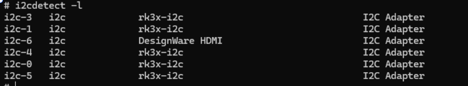
2. 查看i2c-3接口上的设备:
i2cdetect -a 3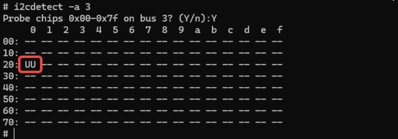
UU代表设备地址为20的设备驱动已加载成功,即上文中提到的I2C3上挂载的NCA9555。
3. 读取指定设备的全部寄存器的值:
i2cdump -f -y 3 0x20(显示i2c3总线上的从设备 0x20 上从 0x00 到 0xff 的所有寄存器地址的值)
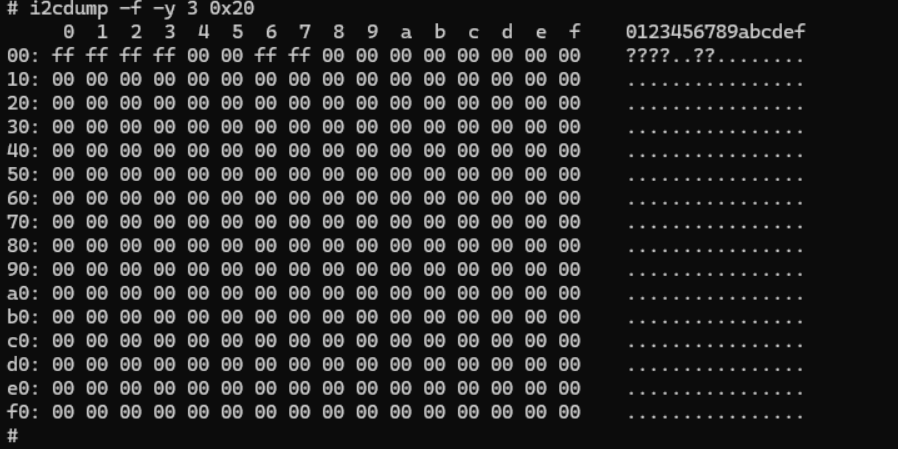
命令成功执行并输出了数据,说明总线3上存在地址为 0x20 的设备,并且基本通信是正常的。
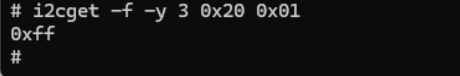
4. 读取指定IIC设备的某个寄存器的值:
i2cget -f -y 3 0x20 0x01(读取地址为0x20器件中的0x01寄存器值)
4. I2C使用---NAPI方式
资料路径
hap包:\05-开发资料\01-OpenHarmory 开发资料\外设测试APP\HAP\I2C_TEST.hap
工程码源:\05-开发资料\01-OpenHarmory 开发资料\外设测试APP\SRC\I2C_TEST
4.1 内核权限设置
我们在终端中执行以下命令为I2C3增加权限:
chmod 777 /dev/i2c-34.2 测试程序讲解
为了直观的看到数据,这里使用逻辑分析仪来捕获发送的I2C信号,用来验证发送数据的正确性。
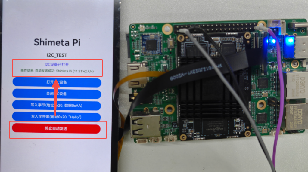
增加权限后,首先点击打开I2C设备,提示打开成功后,点击开始发送"Shimeta Pi"。
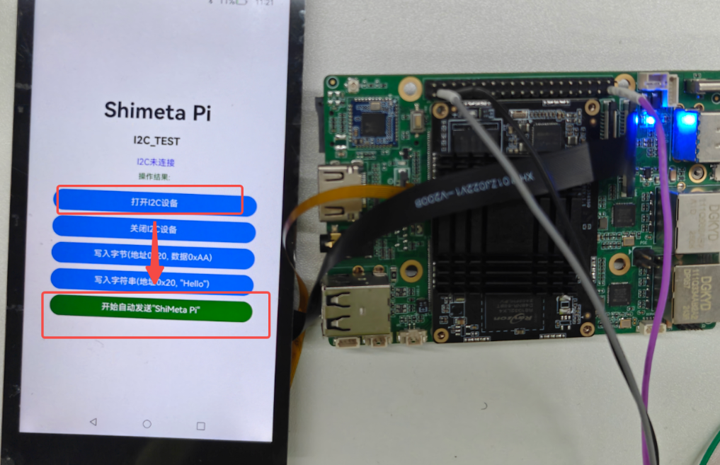
点击以后I2C3会每间隔100ms发送一次字符串"Shimeta Pi"。
开启自动发送以后,我们使用逻辑分析仪采集数据,1S内采集的数据如下:
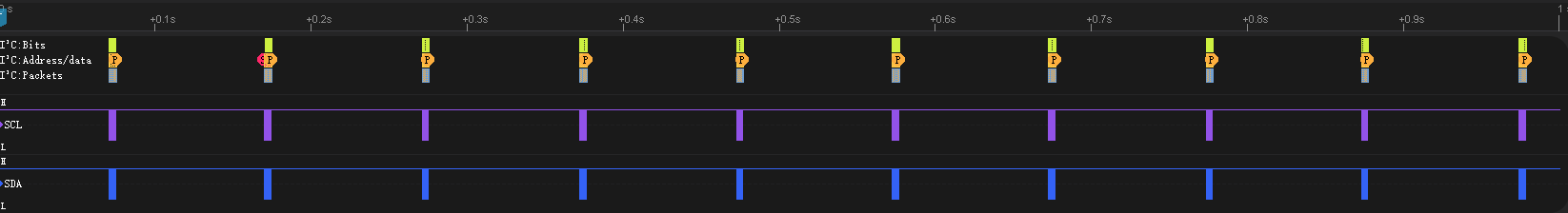
我们可以看到每隔100ms发送的数据如上图所示。
我们以最后2个数据为例进行查看:
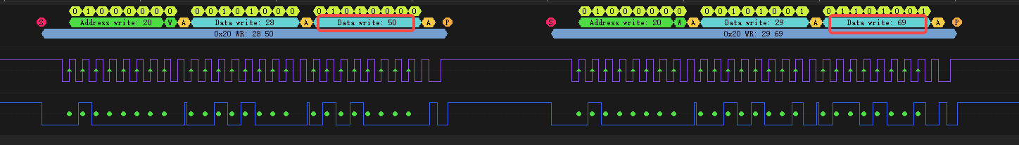
最后两个数据包为0x50和0x69,分别对应十进制的80和105,查看ASCII表如下:
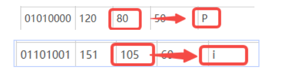
对应的正是字符串"ShiMeta Pi"的最后2位数据。
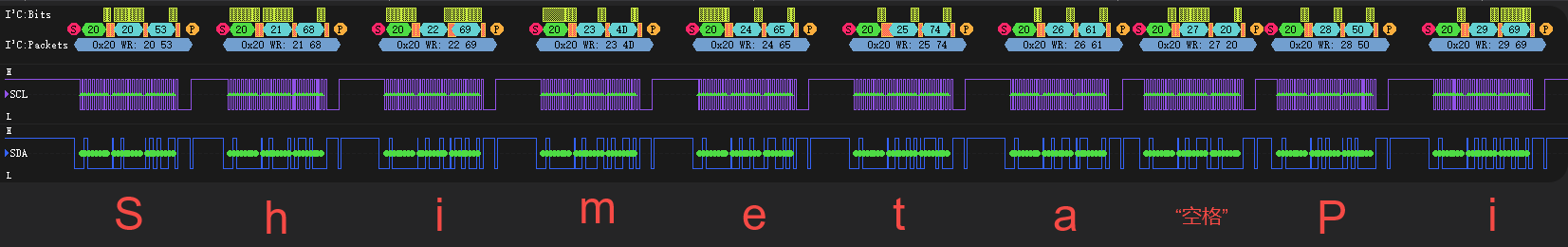
同理整理得数据如下表所示:
| 字符 | 十六进制值 | 十进制值 | 说明 |
|---|---|---|---|
'S' | 0x53 | 83 | 字符S |
'h' | 0x68 | 104 | 字符h |
'i' | 0x69 | 105 | 字符i |
'M' | 0x4D | 77 | 字符M |
'e' | 0x65 | 101 | 字符e |
't' | 0x74 | 116 | 字符t |
'a' | 0x61 | 97 | 字符a |
' ' | 0x20 | 32 | 空格 |
'P' | 0x50 | 80 | 字符P |
'i' | 0x69 | 105 | 字符i |
与逻辑分析仪实际观察的值并无差异。
4.3 部分代码详解
我们这里使用读取系统节点的方式操作I2C从外设进行读写操作,截取部分代码进行介绍。
我们首先介绍一个函数ioctl,是嵌入式领域中非常重要的一个控制操作函数,你可以想象成一个万能遥控器,对着指定的设备按下对应的按键即可让设备执行相应的操作。
函数原型为:
int ioctl(int fd, unsigned long request, ...);参数介绍:
fd是文件描述符,指定操作的设备文件;request是请求码。举个例子,你按下空调遥控器以后,遥控器会发送一段ENC红外编码,空调接收到这串编码以后进行解码操作,比如解码后得到"0x9E",空调内部就会看自己的"任务清单",如果看到"0x9E"表示要开启制冷,那就执行制冷操作。相应的,内核中已经定义了一些I2C的操作,我们只需要发送对应的请求码,内核接收到以后就会执行对应的操作。
...是可变的参数,根据不同的请求码发送不同的数据,比如空调指令码"0x88"表示设置温度,那这个数据可能就是温度数据。
再看我们程序中最重要的一个函数:ioctl(i2c_fd, I2C_RDWR, &i2c_data),是不是就不难理解,它告诉Linux内核:"i2c_fd对应的I2C控制器,要执行一个I2C读写操作,具体的数据是&i2c_data"。
我们再看一下Linux内核提供的i2c-dev.h文件,工程中放置于napi_init.cpp的同级目录下,代码如下:
/*
    i2c-dev.h - i2c-bus driver, char device interface

    Copyright (C) 1995-97 Simon G. Vogl
    Copyright (C) 1998-99 Frodo Looijaard <frodol@dds.nl>

    This program is free software; you can redistribute it and/or modify
    it under the terms of the GNU General Public License as published by
    the Free Software Foundation; either version 2 of the License, or
    (at your option) any later version.

    This program is distributed in the hope that it will be useful,
    but WITHOUT ANY WARRANTY; without even the implied warranty of
    MERCHANTABILITY or FITNESS FOR A PARTICULAR PURPOSE.  See the
    GNU General Public License for more details.

    You should have received a copy of the GNU General Public License
    along with this program; if not, write to the Free Software
    Foundation, Inc., 675 Mass Ave, Cambridge, MA 02139, USA.
*/

#ifndef _LINUX_I2C_DEV_H
#define _LINUX_I2C_DEV_H

#include <linux/types.h>
#include <linux/compiler.h>

/* /dev/i2c-X ioctl commands.  The ioctl's parameter is always an
 * unsigned long, except for:
 *  - I2C_FUNCS, takes pointer to an unsigned long
 *  - I2C_RDWR, takes pointer to struct i2c_rdwr_ioctl_data
 *  - I2C_SMBUS, takes pointer to struct i2c_smbus_ioctl_data
 */
#define I2C_RETRIES 0x0701 /* number of times a device address should
                be polled when not acknowledging */
#define I2C_TIMEOUT 0x0702 /* set timeout in units of 10 ms */

/* NOTE: Slave address is 7 or 10 bits, but 10-bit addresses
 * are NOT supported! (due to code brokenness)
 */
#define I2C_SLAVE   0x0703 /* Use this slave address */
#define I2C_SLAVE_FORCE 0x0706 /* Use this slave address, even if it
                is already in use by a driver! */
#define I2C_TENBIT  0x0704 /* 0 for 7 bit addrs, != 0 for 10 bit */

#define I2C_FUNCS   0x0705 /* Get the adapter functionality mask */

#define I2C_RDWR    0x0707 /* Combined R/W transfer (one STOP only) */

#define I2C_PEC    0x0708 /* != 0 to use PEC with SMBus */
#define I2C_SMBUS   0x0720 /* SMBus transfer */


/* This is the structure as used in the I2C_SMBUS ioctl call */
struct i2c_smbus_ioctl_data {
    __u8 read_write;
    __u8 command;
    __u32 size;
    union i2c_smbus_data __user *data;
};

/* This is the structure as used in the I2C_RDWR ioctl call */
struct i2c_rdwr_ioctl_data {
    struct i2c_msg __user *msgs;   /* pointers to i2c_msgs */
    __u32 nmsgs;         /* number of i2c_msgs */
};

#define  I2C_RDRW_IOCTL_MAX_MSGS    42

#ifdef __KERNEL__
#define I2C_MAJOR   89    /* Device major number    */
#endif

#endif /* _LINUX_I2C_DEV_H */
我们可以发现主要就是一些宏定义,定义了接收到对应请求码需要执行的操作。
#define I2C_RDWR 0x0707 /* Combined R/W transfer (one STOP only) *//* This is the structure as used in the I2C_RDWR ioctl call */
struct i2c_rdwr_ioctl_data {
struct i2c_msg __user *msgs; /* pointers to i2c_msgs */
__u32 nmsgs; /* number of i2c_msgs */
};我们揪出本工程中用到的I2C_RDWR为例(代码如上),它的功能就是执行一个复杂的组合I2C消息传输。参数是一个指向i2c_rdwr_ioctl_data的指针。具体实现的功能是创建一个数组i2c_msg,包含读写操作以及读写组合操作,过程中只产生一个符合I2C标准的STOP信号。
这时候再看发送I2C数据的NAPI函数就好说了:
// I2C写入一个字节
// 参数:offset (寄存器偏移地址), data (要写入的字节)
// 返回:成功返回0,失败返回-1
static napi_value I2cWriteByte(napi_env env, napi_callback_info info)
{
    size_t argc = 2;
    napi_value args[2] = {nullptr};
    napi_value result;

    napi_get_cb_info(env, info, &argc, args, nullptr, nullptr);

    if (argc < 2) {
        napi_create_int32(env, -1, &result);  // 参数错误返回-1
        return result;
    }

    if (!i2c_opened || i2c_fd < 0) {
        napi_create_int32(env, -1, &result);  // 设备未打开返回-1
        return result;
    }

    int32_t offset, data;
    napi_get_value_int32(env, args[0], &offset);
    napi_get_value_int32(env, args[1], &data);

    // 使用ioctl直接操作I2C设备
    struct i2c_rdwr_ioctl_data i2c_data;
    struct i2c_msg msg;
    unsigned char buf[2];

    buf[0] = (unsigned char)offset;  // 寄存器地址
    buf[1] = (unsigned char)data;    // 要写入的数据

    msg.addr = I2C_SLAVE_ADDR;       // I2C设备地址
    msg.flags = 0;                   // 写操作
    msg.len = 2;                     // 数据长度
    msg.buf = buf;                   // 数据缓冲区

    i2c_data.msgs = &msg;
    i2c_data.nmsgs = 1;

    int ret = ioctl(i2c_fd, I2C_RDWR, &i2c_data);

    if (ret < 0) {
        OH_LOG_Print(LOG_APP, LOG_ERROR, GLOBAL_RESMGR, I2C_TAG,
                   "I2C write byte failed: %{public}s", strerror(errno));
        napi_create_int32(env, -1, &result);  // 写入失败返回-1
        return result;
    }

    OH_LOG_Print(LOG_APP, LOG_INFO, GLOBAL_RESMGR, I2C_TAG,
               "I2C write byte success: addr=0x%{public}02X, offset=0x%{public}02X, data=0x%{public}02X",
               I2C_SLAVE_ADDR, offset, data);

    napi_create_int32(env, 0, &result);  // 成功返回0
    return result;
}我们先看函数I2cWriteByte,具体实现功能的过程如下:
- 通过函数
napi_get_cb_info和napi_get_value_int32获取从JavaScript端传进来的偏移值(offset)和数据(data) - 再把2个字节的数据写入到数组
i2c_data中 - 通过
ioctl函数告诉内核执行I2C_RDWR操作,数据为i2c_data - 底层会自动驱动物理层产生对应的
I2C起始信号发送对应的2个字节数据后产生一个停止信号完成I2C信号传输过程
// I2C写入字符串
// 参数:offset (寄存器偏移地址), data (要写入的字符串)
// 返回:成功返回0,失败返回-1
static napi_value I2cWriteString(napi_env env, napi_callback_info info)
{
    size_t argc = 2;
    napi_value args[2] = {nullptr};
    napi_value result;

    napi_get_cb_info(env, info, &argc, args, nullptr, nullptr);

    if (argc < 2) {
        napi_create_int32(env, -1, &result);  // 参数错误返回-1
        return result;
    }

    if (!i2c_opened || i2c_fd < 0) {
        napi_create_int32(env, -1, &result);  // 设备未打开返回-1
        return result;
    }

    int32_t offset;
    napi_get_value_int32(env, args[0], &offset);

    size_t str_length;
    napi_get_value_string_utf8(env, args[1], nullptr, 0, &str_length);

    if (str_length == 0 || str_length > 256) {
        napi_create_int32(env, -1, &result);  // 字符串长度无效返回-1
        return result;
    }

    char* str_buffer = new char[str_length + 1];
    napi_get_value_string_utf8(env, args[1], str_buffer, str_length + 1, &str_length);

    // 使用ioctl直接操作I2C设备,逐字节写入
    struct i2c_rdwr_ioctl_data i2c_data;
    struct i2c_msg msg;
    unsigned char buf[2];
    int success_count = 0;

    for (size_t i = 0; i < str_length; i++) {
        buf[0] = (unsigned char)(offset + i);  // 寄存器地址
        buf[1] = (unsigned char)str_buffer[i]; // 要写入的数据

        msg.addr = I2C_SLAVE_ADDR;             // I2C设备地址
        msg.flags = 0;                         // 写操作
        msg.len = 2;                           // 数据长度
        msg.buf = buf;                         // 数据缓冲区

        i2c_data.msgs = &msg;
        i2c_data.nmsgs = 1;

        int ret = ioctl(i2c_fd, I2C_RDWR, &i2c_data);

        if (ret < 0) {
            OH_LOG_Print(LOG_APP, LOG_ERROR, GLOBAL_RESMGR, I2C_TAG,
                       "I2C write string failed at byte %{public}zu: %{public}s", i, strerror(errno));
            break;
        }
        success_count++;
    }

    delete[] str_buffer;

    if (success_count == (int)str_length) {
        OH_LOG_Print(LOG_APP, LOG_INFO, GLOBAL_RESMGR, I2C_TAG,
                   "I2C write string success: addr=0x%{public}02X, offset=0x%{public}02X, length=%{public}d",
                   I2C_SLAVE_ADDR, offset, success_count);

        napi_create_int32(env, 0, &result);  // 成功返回0
    } else {
        OH_LOG_Print(LOG_APP, LOG_WARN, GLOBAL_RESMGR, I2C_TAG,
                   "I2C write string partial success: %{public}d/%{public}zu bytes written", success_count, str_length);

        napi_create_int32(env, -1, &result);  // 部分失败返回-1
    }

    return result;
}而I2C写字符串的函数就简单了,获取字符串长度后,执行对应次数的字符传输即可,这里就不再进行解释了。