HOME
Shop
  • English
  • 简体中文
HOME
Shop
  • English
  • 简体中文
  • Product Series

    • FPGA+ARM

      • GM-3568JHF

        • 1. Introduction

          • About GM-3568JHF
        • 2. Quick Start

          • 00 Introduction
          • 01 Environment Setup
          • 02 Compilation Instructions
          • 03 Flashing Guide
          • 04 Debug Tools
          • 05 Software Update
          • 06 View Information
          • 07 Test Commands
          • 08 App Compilation
          • 09 Source Code Acquisition
        • 3. Peripherals and Interfaces

          • 01 USB
          • 02 Display and Touch
          • 03 Ethernet
          • 04 WIFI
          • 05 Bluetooth
          • 06 TF-Card
          • 07 Audio
          • 08 Serial Port
          • 09 CAN
          • 10 RTC
        • 4. Application Development

          • 01 UART read and write case
          • 02 Key detection case
          • 03 LED light flashing case
          • 04 MIPI screen detection case
          • 05 Read USB device information example
          • 06 FAN Detection Case
          • 07 FPGA FSPI Communication Case
          • 08 FPGA DMA read and write case
          • 09 GPS debugging case
          • 10 Ethernet Test Cases
          • 11 RS485 reading and writing examples
          • 12 FPGA IIC read and write examples
          • 13 PN532 NFC card reader case
          • 14 TF card reading and writing case
        • 5. QT Development

          • 01 ARM64 cross compiler environment construction
          • 02 QT program added automatic startup service
        • 6. RKNN_NPU Development

          • 01 RK3568 NPU Overview
          • 02 Development Environment Setup
          • Run Official YOLOv5 Example
          • Model Conversion Detailed Explanation
          • Run Custom Model on Board
        • 7. FPGA Development

          • ARM and FPGA Communication
          • /fpga-arm/GM-3568JHF/FPGA/ch02-FPGA-Development-Manual.html
        • 8. Others

          • 01 Modification of the root directory file system
          • 02 System auto-start service
        • 9. Download

          • Download Resources
    • ShimetaPi

      • M4-R1

        • 1. Introduction

          • 1.1 About M4-R1
        • 2. Quick Start

          • 2.1 OpenHarmony Overview
          • 2.2 Image Burning
          • 2.3 Development Environment Preparation
          • 2.4 Hello World Application
        • 3. Application Development

          • 3.1 Getting Started

            • 3.1.1 ArkTS Language Overview
            • 3.1.2 UI Components (Part 1)
            • 3.1.3 UI Components (Part 2)
            • 3.1.4 UI Components (Part 3)
          • 3.2 Advanced

            • 3.2.1 Getting Started Guide
            • 3.2.2 Usage of Third Party Libraries
            • 3.2.3 Deployment of the Application
            • 3.2.4 Factory Reset
            • 3.2.5 System Debug
            • 3.2.6 APP Stability Testing
            • 3.2.7 Application Testing
          • 3.3 Getting Docs

            • 3.3.1 Official Website Information
          • 3.4 Development Instructions

            • 3.4.1 Full SDK
            • 3.4.2 Introduction of Third Party Libraries
            • 3.4.3 Introduction of HDC Tool
            • 3.4.4 Restore Factory Mode
            • 3.4.5 Update System API
          • 3.5 First Application

            • 3.5.1 First ArkTS App
          • 3.6 Application Demo

            • 3.6.1 UART Tool
            • 3.6.2 Graphics Tablet
            • 3.6.3 Digital Clock
            • 3.6.4 WIFI Tool
        • 4. Device Development

          • 4.1 Ubuntu Environment Development

            • 4.1.1 Environment Setup
            • 4.1.2 Download Source Code
            • 4.1.3 Compile Source Code
          • 4.2 Using DevEco Device Tool

            • 4.2.1 Tool Introduction
            • 4.2.2 Environment Construction
            • 4.2.3 Import SDK
            • 4.2.4 Function Introduction
        • 5. Peripherals and Interfaces

          • 5.1 Raspberry Pi Interfaces
          • 5.2 GPIO Interface
          • 5.3 I2C Interface
          • 5.4 SPI Communication
          • 5.5 PWM Control
          • 5.6 Serial Port Communication
          • 5.7 TF Card Slot
          • 5.8 Display Screen
          • 5.9 Touch Screen
          • 5.10 Audio
          • 5.11 RTC
          • 5.12 Ethernet
          • 5.13 M.2
          • 5.14 MINI PCIE
          • 5.15 Camera
          • 5.16 WIFI BT
          • 5.17 HAT
        • 6. FAQ

          • 6.1 Download Link
      • M5-R1

        • 1. Introduction

          • M5-R1 Development Documentation
        • 2. Quick Start

          • OpenHarmony Overview
          • Image Burning
          • Development Environment Preparation
          • Hello World Application and Deployment
        • 3. Peripherals and Interfaces

          • 3.1 Raspberry Pi Interfaces
          • 3.2 GPIO Interface
          • 3.3 I2C Interface
          • 3.4 SPI Communication
          • 3.5 PWM Control
          • 3.6 Serial Port Communication
          • 3.7 TF Card Slot
          • 3.8 Display Screen
          • 3.9 Touch Screen
          • 3.10 Audio
          • 3.11 RTC
          • 3.12 Ethernet
          • 3.13 M.2
          • 3.14 MINI PCIE
          • 3.15 Camera
          • 3.16 WIFI BT
          • 3.17 HAT
        • 4. Application Development

          • 4.1 Getting Started

            • 4.1.1 ArkTS Language Overview
            • 4.1.2 UI Components (Part 1)
            • 4.1.3 UI Components (Part 2)
            • 4.1.4 UI Components (Part 3)
          • 4.2 Advanced

            • 4.2.1 Getting Started Guide
            • 4.2.2 Usage of Third Party Libraries
            • 4.2.3 Deployment of the Application
            • 4.2.4 Factory Reset
            • 4.2.5 System Debug
            • 4.2.6 APP Stability Testing
            • 4.2.7 Application Testing
        • 5. Device Development

          • 5.1 Environment Setup
          • 5.2 Download Source Code
          • 5.3 Compile Source Code
        • 6. Download

          • Data Download
    • OpenHarmony

      • SC-3568HA

        • 1. Introduction

          • 1.1 About SC-3568HA
        • 2. Quick Start

          • 2.1 OpenHarmony Overview
          • 2.2 Image Burning
          • 2.3 Development Environment Preparation
          • 2.4 Hello World Application
        • 3. Application Development

          • 3.1 ArkUI

            • 3.1.1 ArkTS Language Overview
            • 3.1.2 UI Components (Part 1)
            • 3.1.3 UI Components (Part 2)
            • 3.1.4 UI Components (Part 3)
          • 3.2 Advanced

            • 3.2.1 Getting Started Guide
            • 3.2.2 Usage of Third Party Libraries
            • 3.2.3 Deployment of the Application
            • 3.2.4 Factory Reset
            • 3.2.5 System Debug
            • 3.2.6 APP Stability Testing
            • 3.2.7 Application Testing
        • 4. Device Development

          • 4.1 Environment Setup
          • 4.2 Download Source Code
          • 4.3 Compile Source Code
        • 5. Peripherals and Interfaces

          • 5.1 Raspberry Pi Interfaces
          • 5.2 GPIO Interface
          • 5.3 I2C Interface
          • 5.4 SPI Communication
          • 5.5 PWM Control
          • 5.6 Serial Port Communication
          • 5.7 TF Card Slot
          • 5.8 Display Screen
          • 5.9 Touch Screen
          • 5.10 Audio
          • 5.11 RTC
          • 5.12 Ethernet
          • 5.13 M.2
          • 5.14 MINI PCIE
          • 5.15 Camera
          • 5.16 WIFI BT
          • 5.17 HAT
        • 6. FAQ

          • 6.1 Download Link
      • M-K1HSE

        • 1. Introduction

          • 1.1 Product Introduction
        • 2. Quick Start

          • 2.1 Debug Tool Installation
          • 2.2 Development Environment Setup
          • 2.3 Source Code Download
          • 2.4 Build Instructions
          • 2.5 Flashing Guide
          • 2.6 APT Update Sources
          • 2.7 View Board Info
          • 2.8 CLI LED and Key Test
          • 2.9 GCC Build Programs
        • 3. Application Development

          • 3.1 Basic Application Development

            • 3.1.1 Development Environment Preparation
            • 3.1.2 First Application HelloWorld
            • 3.1.3 Develop HAR Package
          • 3.2 Peripheral Application Cases

            • 3.2.1 UART Read/Write
            • 3.2.2 Key Demo
            • 3.2.3 LED Flash
        • 4. Peripherals and Interfaces

          • 4.1 Standard Peripherals

            • 4.1.1 USB
            • 4.1.2 Display and Touch
            • 4.1.3 Ethernet
            • 4.1.4 WIFI
            • 4.1.5 Bluetooth
            • 4.1.6 TF Card
            • 4.1.7 Audio
            • 4.1.8 Serial Port
            • 4.1.9 CAN
            • 4.1.10 RTC
          • 4.2 Interfaces

            • 4.2.1 Audio
            • 4.2.2 RS485
            • 4.2.3 Display
            • 4.2.4 Touch
        • 5. System Customization Development

          • 5.1 System Porting
          • 5.2 System Customization
          • 5.3 Driver Development
          • 5.4 System Debugging
          • 5.5 OTA Upgrade
        • 6. Download

          • 6.1 Download
    • EVS-Camera

      • CF-NRS1

        • 1. Introduction

          • 1.1 About CF-NRS1
          • 1.2 Event-Based Concepts
          • 1.3 Quick Start
          • 1.4 Resources
        • 2. Development

          • 2.1 Development Overview

            • 2.1.1 Shimetapi Hybrid Camera SDK Introduction
          • 2.2 Environment & API

            • 2.2.1 Environment Overview
            • 2.2.2 Development API Overview
          • 2.3 Linux Development

            • 2.3.1 Linux SDK Introduction
            • 2.3.2 Linux SDK API
            • 2.3.3 Linux Algorithm
            • 2.3.4 Linux Algorithm API
          • 2.4 Service & Web

            • 2.4.1 EVS Server
            • 2.4.2 Time Server
            • 2.4.3 EVS Web
        • 3. Download

          • 3.1 Download
        • 4. Common Problems

          • 4.1 Common Problems
      • CF-CRA2

        • 1. Introduction

          • 1.1 About CF-CRA2
        • 2. Download

          • 2.1 Download
      • EVS Module

        • 1. Related Concepts
        • 2. Hardware Preparation and Environment Configuration
        • 3. Example Program User Guide
        • Resources Download
    • AI-model

      • 1684XB-32T

        • 1. Introduction

          • AIBOX-1684XB-32 Introduction
        • 2. Quick Start

          • First time use
          • Network Configuration
          • Disk usage
          • Memory allocation
          • Fan Strategy
          • Firmware Upgrade
          • Cross-Compilation
          • Model Quantization
        • 3. Application Development

          • 3.1 Development Introduction

            • Sophgo SDK Development
            • SOPHON-DEMO Introduction
          • 3.2 Large Language Models

            • Deploying Llama3 Example
            • /ai-model/AIBOX-1684XB-32/application-development/LLM/Sophon_LLM_api_server-Development-AIBOX-1684XB-32.html
            • /ai-model/AIBOX-1684XB-32/application-development/LLM/MiniCPM-V-2_6-AIBOX-1684XB-32.html
            • /ai-model/AIBOX-1684XB-32/application-development/LLM/Qwen-2-5-VL-demo-Development-AIBOX-1684XB-32.html
            • /ai-model/AIBOX-1684XB-32/application-development/LLM/Qwen-3-chat-demo-Development-AIBOX-1684XB-32.html
            • /ai-model/AIBOX-1684XB-32/application-development/LLM/Qwen3-Qwen Agent-MCP.html
            • /ai-model/AIBOX-1684XB-32/application-development/LLM/Qwen3-langchain-AI Agent.html
          • 3.3 Deep Learning

            • ResNet (Image Classification)
            • LPRNet (License Plate Recognition)
            • SAM (Universal Image Segmentation Foundation Model)
            • YOLOv5 (Object Detection)
            • OpenPose (Human Keypoint Detection)
            • PP-OCR (Optical Character Recognition)
        • 4. Download

          • Resource Download
      • 1684X-416T

        • 1. Introduction

          • AIBOX-1684X-416 Introduction
        • 2. Demo Simple Operation Guide

          • Simple instructions for using shimeta smart monitoring demo
      • RDK-X5

        • 1. Introduction

          • RDK-X5 Hardware Introduction
        • 2. Quick Start

          • RDK-X5 Quick Start
        • 3. Application Development

          • 3.1 AI Online Model Development

            • AI Online Development - Experiment01
            • AI Online Development - Experiment02
            • AI Online Development - Experiment03
            • AI Online Development - Experiment04
            • AI Online Development - Experiment05
            • AI Online Development - Experiment06
          • 3.2 Large Language Models (Voice)

            • Voice LLM Application - Experiment01
            • Voice LLM Application - Experiment02
            • Voice LLM Application - Experiment03
            • Voice LLM Application - Experiment04
            • Voice LLM Application - Experiment05
            • Voice LLM Application - Experiment06
          • 3.3 40pin-IO Development

            • 40pin IO Development - Experiment01
            • 40pin IO Development - Experiment02
            • 40pin IO Development - Experiment03
            • 40pin IO Development - Experiment04
            • 40pin IO Development - Experiment05
            • 40pin IO Development - Experiment06
            • 40pin IO Development - Experiment07
          • 3.4 USB Module Development

            • USB Module Usage - Experiment01
            • USB Module Usage - Experiment02
          • 3.5 Machine Vision

            • Machine Vision Technology Development - Experiment01
            • Machine Vision Technology Development - Experiment02
            • Machine Vision Technology Development - Experiment03
            • Machine Vision Technology Development - Experiment04
          • 3.6 ROS2 Base Development

            • ROS2 Basic Development - Experiment01
            • ROS2 Basic Development - Experiment02
            • ROS2 Basic Development - Experiment03
            • ROS2 Basic Development - Experiment04
      • RDK-S100

        • 1. Introduction

          • 1.1 About RDK-S100
        • 2. Quick Start

          • 2.1 First Use
        • 3. Application Development

          • 3.1 AI Online Model Development

            • 3.1.1 Volcano Engine Doubao AI
            • 3.1.2 Image Analysis
            • 3.1.3 Multimodal Visual Analysis
            • 3.1.4 Multimodal Image Comparison
            • 3.1.5 Multimodal Document Analysis
            • 3.1.6 Camera AI Vision Analysis
          • 3.2 Large Language Models

            • 3.2.1 Speech Recognition
            • 3.2.2 Voice Conversation
            • 3.2.3 Multimodal Image Analysis
            • 3.2.4 Multimodal Image Comparison
            • 3.2.5 Multimodal Document Analysis
            • 3.2.6 Multimodal Vision Application
          • 3.3 40pin-IO Development

            • 3.3.1 GPIO Output LED Blink
            • 3.3.2 GPIO Input
            • 3.3.3 Key Control LED
            • 3.3.4 PWM Output
            • 3.3.5 Serial Output
            • 3.3.6 I2C Experiment
          • 3.4 USB Module Development

            • 3.4.1 USB Voice Module
            • 3.4.2 Sound Source Localization
          • 3.5 Machine Vision

            • 3.5.1 USB Camera
            • 3.5.2 Image Processing Basics
            • 3.5.3 Object Detection
            • 3.5.4 Image Segmentation
          • 3.6 ROS2 Base Development

            • 3.6.1 Environment Setup
            • 3.6.2 Create and Build Workspace
            • 3.6.3 ROS2 Topic Communication
            • 3.6.4 ROS2 Camera Application
    • Core-Board

      • C-3568BQ

        • 1. Introduction

          • C-3568BQ Introduction
      • C-3588LQ

        • 1. Introduction

          • C-3588LQ Introduction
      • GC-3568JBAF

        • 1. Introduction

          • GC-3568JBAF Introduction
      • C-K1BA

        • 1. Introduction

          • C-K1BA Introduction

GPIO 接口

1. GPIO介绍

GPIO是General Purpose I/O的缩写,即通用输入输出端口,简单来说就是MCU/CPU可控制的引脚, 这些引脚通常有多种功能,最基本的是高低电平输入检测和输出,部分引脚还会与主控器的片上外设绑定, 如作为串口、I2C、网络、电压检测的通讯引脚。

2. GPIO命名

Rockchip Pin的ID按照 控制器(bank)+端口(port)+索引序号(pin) 组成。

  • 控制器和GPIO控制器数量一致
  • 端口固定 A、B、C和D,每个端口仅有8个索引号,(a=0,b=1,c=2,d=3)
  • 索引序号固定 0、1、2、3、4、5、6、7

RK3568具有5个GPIO控制器,每个控制器可以控制32个IO,作为GPIO功能时, 端口⾏为由GPIO控制器寄存器配置。

Tips

GPIO1_A4表达的意思为第1组控制器,端口号为A,索引号为4。 该引脚号的计算公式为32 x 1 + 0 x 8 + 4 = 36

3. 使用GPIO sysfs接口控制IO

命令行的方式

在Linux中,最常见的读写GPIO方式就是用GPIO sysfs interface, 是通过操作 /sys/class/gpio 目录下的 export 、 unexport 、gpio{N}/direction, gpio{N} /value (用实际引脚号替代{N})等文件实现的,经常出现shell脚本里面。 在kernel 4.8开始,加入了libgpiod的支持;而原有基于sysfs的访问方式,将被逐渐放弃。

以M4-R1举例,在40PIN引脚上挑选3个GPIO
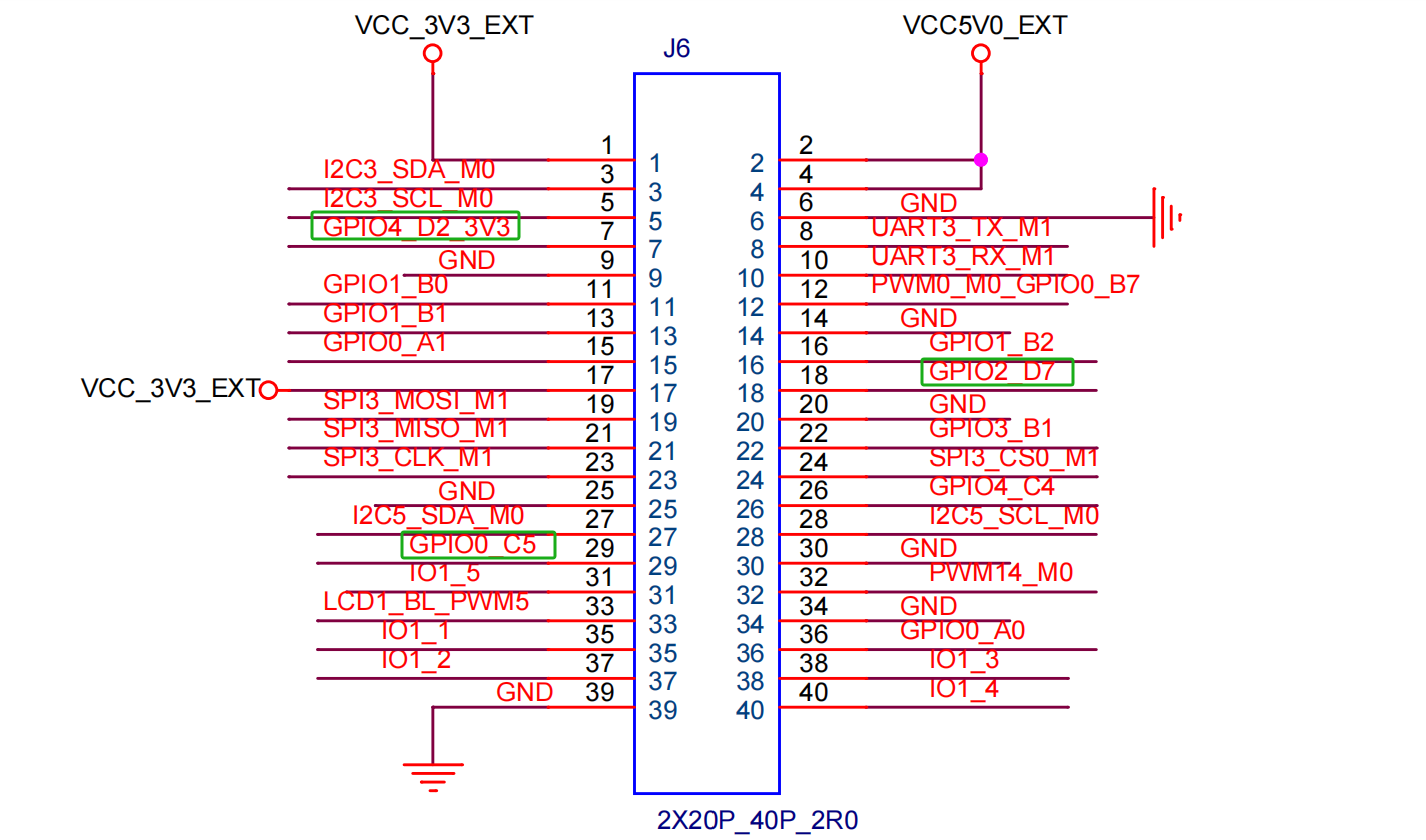
TOOL
引脚控制器端口号索引号计算结果PIN
GPIO4_D24D2154 (32 x 4 + 8 x 3 + 2)7
GPIO2_D72D795 (32 x 2 + 8 x 3 + 7)18
GPIO0_C50C521 (32 x 0 + 8 x 2 + 5)29
	#以下所有操作均需要打开管理者权限使用(鸿蒙系统默认就是管理者权限)
    #使能引脚GPIO4_D2
    echo 154 > /sys/class/gpio/export

    #设置引脚为输入模式
    echo in > /sys/class/gpio/gpio154/direction
    #读取引脚的值
    cat /sys/class/gpio/gpio154/value

    #设置引脚为输出模式
    echo out > /sys/class/gpio/gpio154/direction
    #设置引脚为低电平
    echo 0 > /sys/class/gpio/gpio154/value
    #设置引脚为高电平
    echo 1 > /sys/class/gpio/gpio154/value

    #复位引脚
    echo 154 > /sys/class/gpio/unexport

4. 拓展GPIO口

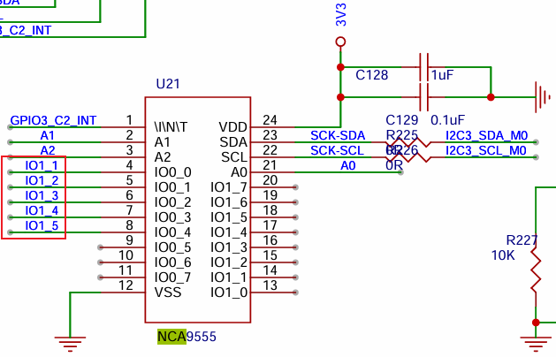
M4-R1上带有NCA9555芯片,NCA9555是一款24引脚CMOS器件,提供16位通用并行I2C总线数输入/输出GPIO扩展功能

4.1 拓展GPIO口引脚

目前从该芯片引出了5个IO出来使用,连接到了40PIN引脚上
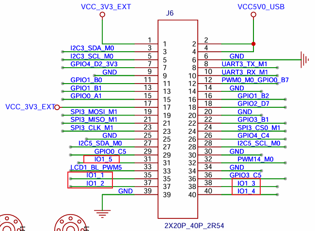
TOOLTOOL
NCA955540PIN
IO1_135
IO1_237
IO1_338
IO1_440
IO1_531

4.2 拓展GPIO口使用

该芯片为I2C通讯,挂载在I2C3下,驱动文件已添加,DTS配置如下:

  • /arch/arm64/boot/dts/rockchip/rk3568-toybrick-x0-linux.dts
	&i2c3{
	nca9555:nca9555@20{
		reg=<0x20>;
		compatible = "novosense,nca9555";
		status="okay";
		gpio-controller;
		#gpio-cells = <2>;
		};
	};

备注

在内核中使用NCA9555的IO口,其方式与普通的GPIO使用方式基本一致

例如:

	//使用普通GPIO
    &vcc3v3_lcd0_n {
        gpio = <&gpio0 RK_PC7 GPIO_ACTIVE_HIGH>;
        enable-active-high;
    };

    //使用NCA9555的IO
    &vcc3v3_lcd1_n {
        gpio = <&nca9555 3 GPIO_ACTIVE_HIGH>;   //对应NCA9555 IO0_3
        enable-active-high;
    };

    &vcc3v3_lcd2_n {
        gpio = <&nca9555 10 GPIO_ACTIVE_HIGH>;   //对应NCA9555 IO1_2
        enable-active-high;
    };

Edit this page on GitHub
Last Updated:
Contributors: zwhuang
Prev
5.1 Raspberry Pi Interfaces
Next
5.3 I2C Interface