HOME
Shop
  • English
  • 简体中文
HOME
Shop
  • English
  • 简体中文
  • Product Series

    • FPGA+ARM

      • GM-3568JHF

        • 1. Introduction

          • GM-3568JHF Introduction
        • 2. Quick Start

          • 01 Environment Construction
          • 02 Compilation Instructions
          • 03 Burning Guide
          • 04 Debugging Tools
          • 05 Software Update
          • 06 View information
          • 07 Test Command
          • 08 Application Compilation
          • 09 Source code acquisition
        • 3. Peripherals and Interfaces

          • USB
          • Display and touch
          • Ethernet
          • WIFI
          • Bluetooth
          • TF-Card
          • Audio
          • Serial Port
          • CAN
          • RTC
        • 4. Application Development

          • 01 UART read and write case
          • 02 Key detection case
          • 03 LED light flashing case
          • 04 MIPI screen detection case
          • 05 Read USB device information example
          • 06 FAN Detection Case
          • 07 FPGA FSPI Communication Case
          • 08 FPGA DMA read and write case
          • 09 GPS debugging case
          • 10 Ethernet Test Cases
          • 11 RS485 reading and writing examples
          • 12 FPGA IIC read and write examples
          • 13 PN532 NFC card reader case
          • 14 TF card reading and writing case
        • 5. QT Development

          • 01 ARM64 cross compiler environment construction
          • 02 QT program added automatic startup service
        • 6. Others

          • 01 Modification of the root directory file system
          • 02 System auto-start service
    • ShimetaPi

      • M4-R1

        • Introduction

          • M4-R1 Introduction
        • Get started quickly

          • OpenHarmony概述
          • 镜像烧录
          • 开发环境准备
          • Hello World应用以及部署
        • Application Development

          • getting Started

            • 第一章 ArkTS语言简介
            • 第二章 UI组件介绍和实际应用(上)
            • 第三章 UI组件介绍和实际应用(中)
            • 第四章 UI组件介绍和实际应用(下)
          • Advanced

            • 第一章 入门指引
            • 第二章 三方库的引用和使用
            • 第三章 应用编译以及部署
            • 第四章 命令行恢复出厂设置
            • 第五章 系统调试--HDC调试
            • 第六章 APP 稳定性测试
            • 第七章 应用测试
        • Equipment Development

          • 第一章 环境搭建
          • 第二章 下载源码
          • 第三章 编译源码
        • Peripherals and interfaces

          • 树莓派接口
          • GPIO 接口
          • I2C 接口
          • SPI通信
          • PWM控制
          • 串口通讯
          • TF Card
          • 屏幕
          • 触摸
          • 音频
          • RTC
          • Ethernet
          • M.2
          • MINI-PCIE
          • Camera
          • WIFI&BT
          • 树莓派拓展板
        • Frequently asked questions

          • 资源下载
      • M5-R1

        • Introduction

          • Introduction to ShimetaPi M5-R1
    • OpenHarmony

      • SC-3568HA

        • Introduction

          • SC-3568HA Overview
        • Quick Start Guide

          • OpenHarmony Overview
          • Image Flashing
          • Setting Up the Development Environment
          • Hello World Application and Deployment
        • Application Development

          • ArkUI

            • Chapter 1 Introduction to ArkTS Language
            • Chapter 2 Introduction to UI Components and Practical Applications (Part 1)
            • Chapter 3 Introduction to UI Components and Practical Applications (Part 2)
            • Chapter 4 Introduction to UI Components and Practical Applications (Part 3)
          • Expand

            • Chapter 1 Getting Started Guide
            • Chapter 2 Referencing and Using Third-Party Libraries
            • Chapter 3: Application Compilation and Deployment
            • Chapter 4: Command-Line Factory Reset
            • Chapter 5: System Debugging -- HDC (Huawei Device Connector) Debugging
            • Chapter 6 APP Stability Testing
            • Chapter 7 Application Testing
        • Device Development

          • Chapter 1 Environment Setup
          • Chapter 2 Download Source Code
          • Chapter 3 Compiling Source Code
        • Peripheral And Iinterface

          • Raspberry Pi interface
          • GPIO Interface
          • I2C Interface
          • SPI communication
          • PWM (Pulse Width Modulation) control
          • Serial port communication
          • TF Card
          • Display Screen
          • Touch
          • Audio
          • RTC
          • Ethernet
          • M.2
          • MINI-PCIE
          • Camera
          • WIFI&BT
          • Raspberry Pi expansion board
        • Frequently Asked Questions

          • Resource Downloads
      • M-K1HSE

        • Introduction

          • M-K1HSE Introduction
        • Quick Start

          • Development environment construction
          • Source code acquisition
          • Compilation Notes
          • Burning Guide
        • Peripherals and interfaces

          • 01 Audio
          • 02 RS485
          • 03 Display
        • System customization development

          • System transplant
          • System customization
          • Driver Development
          • System Debugging
          • OTA Update
    • EVS-Camera

      • CF-NRS1

        • 1. Introduction

          • Event Camera Technical Documentation
        • 2. Quick Start

          • Host driver and software installation
        • 3. SDK application development

          • API Usage Instructions
      • CF-CRA2

        • Introduction

          • About CF-NRS1
    • AI-model

      • 1684XB-32T

        • Introduction

          • AIBOX-1684XB-32 Introduction
        • Get started quickly

          • First time use
          • Network Configuration
          • Disk usage
          • Memory allocation
          • Fan Strategy
          • Firmware Upgrade
        • Deployment Tutorial

          • Algorithm deployment
          • Deploy Llama3 Example
        • Application Development

          • Sophgo SDK Development
          • Sophon LLM_api_server development
          • Deploy MiniCPM-V-2_6
          • Qwen-2-5-VL Image and Video Recognition DEMO
          • Qwen3-chat-DEMO
          • Qwen3-Qwen Agent-MCP-Demo
          • Qwen3-langchain-AI Agent
      • 1684X-416T

        • Introduction

          • AIBOX-1684X-416 Introduction
        • Demo simple operation guide

          • Simple instructions for using shimeta smart monitoring demo
    • Core-Board

      • C-3568BQ

        • Introduction

          • C-3568BQ Overview
      • C-3588LQ

        • Introduction

          • C-3588LQ Introduction
      • GC-3568JBAF

        • Introduction

          • GC-3568JBAF Introduction
      • C-K1BA

        • Introduction

          • C-K1BA Introduction

树莓派拓展板

1. 树莓派RS485/CAN拓展板

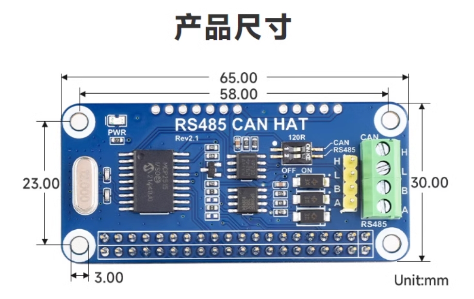
M4-R1不支持CAN通信,可以使用该拓展板通过SPI通讯来拓展出一路CAN。

拓展板实物图:
TOOL

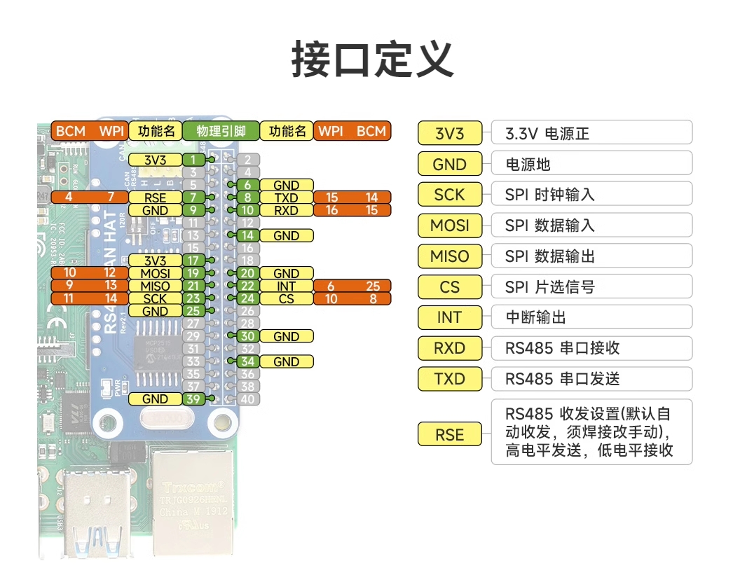
拓展板引脚对照图:

TOOL

2. CAN通讯

2.1 DTS配置

该拓展板使用MCP2515来实现CAN通信,关于MCP2515的dts配置如下:

注意

固件中没有适配MCP2515,若需要使用CAN接口,根据以下内容配置即可

  • arch/arm64/boot/dts/rockchip/rk3568-toybrick-x0-linux.dts
    / {
        mcp251x_clk: mcp251x-clk {
                    compatible = "fixed-clock";
                    #clock-cells = <0>;
                    clock-frequency = <12000000>;       //根据MCP2515模块的硬件晶振设置 12MHz
            };
    };

    &spi3{
    	status = "okay";
        pinctrl-0 = <&spi3m1_cs0 &spi3m1_pins>;
        pinctrl-1 = <&spi3m1_cs0 &spi3m1_pins_hs>;
        max-freq = <5000000>;
        mcp2515: mcp2515 {
            compatible = "microchip,mcp2515";
            pinctrl-names = "default";
            pinctrl-0 = <&mcp2515_irq1_pins>;
            reg = <0>;
            clocks = <&mcp251x_clk>;
            spi-max-frequency = <2000000>;
            interrupt-parent = <&gpio3>;
            interrupts = <RK_PB1 IRQ_TYPE_EDGE_FALLING>;
            vdd-supply = <&vcc3v3_sys>;
            xceiver-supply = <&vcc3v3_sys>;
            status = "okay";
        };
    };

    &pinctrl {
        mcp2515 {
            mcp2515_irq1_pins: mcp2515-irq1-pins {
                            rockchip,pins = <3 RK_PB1 RK_FUNC_GPIO &pcfg_pull_none>;
                    };
            };
    };

2.2 CAN收发测试

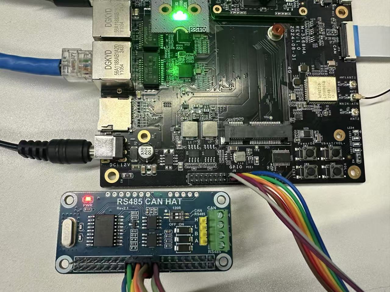
首先将拓展板与M4-R1板卡40PIN相连

连接如下图:
TOOL

2.2.1 回环测试

板卡带有CAN测试工具,连接好拓展板后输入命令测试

注意1.回环测试无需连接CAN_H和CAN_L;

2.pin脚连接方式为一一对应,即1 pin脚对应拓展板1脚;

设置波特率以及回环模式:

    #将CAN0接口关闭
    ip link set can0 down
    #设置比特率为 250000Hz,同时启用回环模式
    ip link set can0 type can bitrate 250000 loopback on
    #将CAN0接口启用
    ip link set can0 up

打开两个终端窗口,测试can0自收发:

    #终端1
    candump can0

    #终端2
    cansend can0 -i 0x321 0x11 0x22 0x33 0x44 0x55 0x66 0x77 0x88

    #或者只使用一个终端
    candump can0 &
    cansend can0 -i 0x321 0x11 0x22 0x33 0x44 0x55 0x66 0x77 0x88

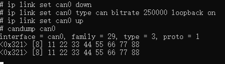
测试效果如下:

  • 终端1:
TOOL
  • 终端2:
TOOL

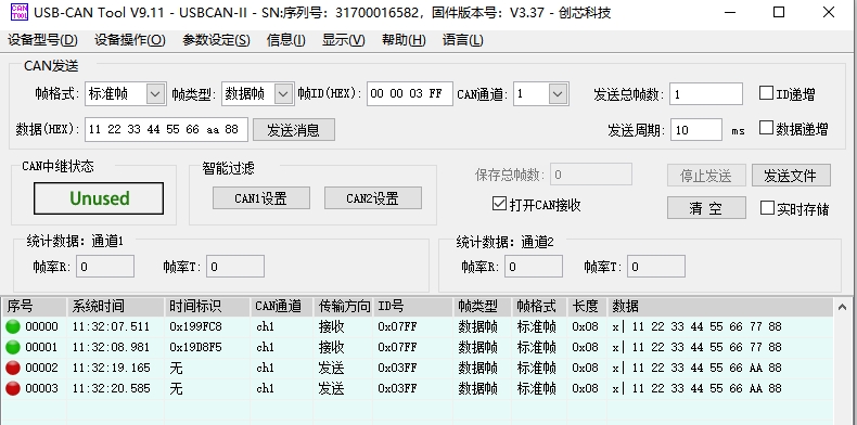
2.2.2 与CAN分析仪通信测试

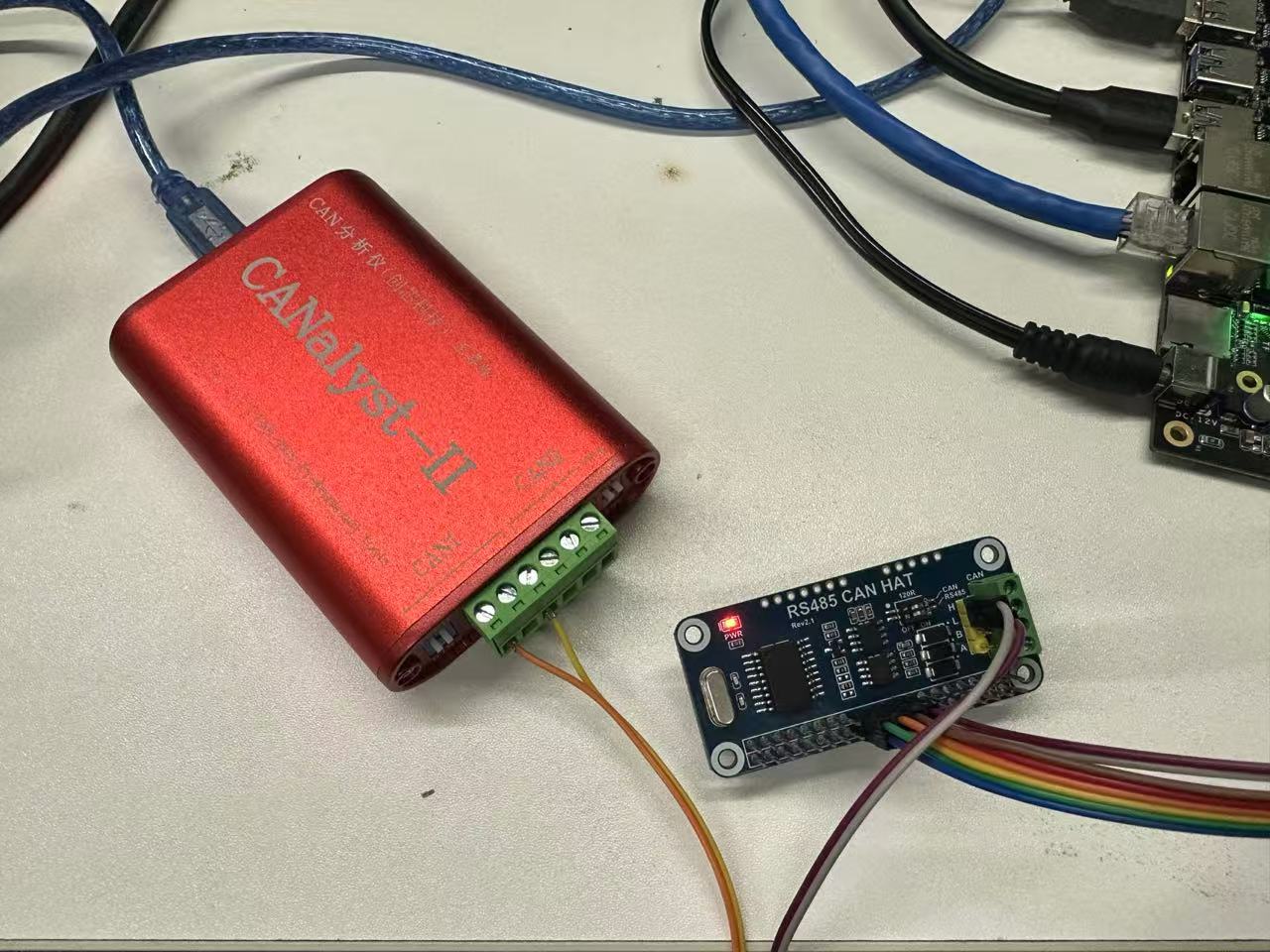
将拓展板和分析仪进行连接。

TOOL
扩展板CAN分析仪
CAN_HCAN_H
CAN_LCAN_L

设置波特率并进行测试

    #将CAN0接口关闭
    sudo ip link set can0 down
    #设置比特率为 250000
    sudo ip link set can0 type can bitrate 250000
    #将CAN0接口启用
    sudo ip link set can0 up

    #发送(标准帧,数据帧,ID:7ff,date:11223344556677)
    cansend can0 -i 0x7ff 0x11 0x22 0x33 0x44 0x55 0x66 0x77 0x88

    #接收
    candump can0
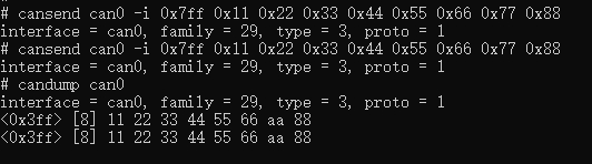
  • 终端测试效果:
TOOL
  • CAN分析仪测试效果:
TOOL

3. RS485

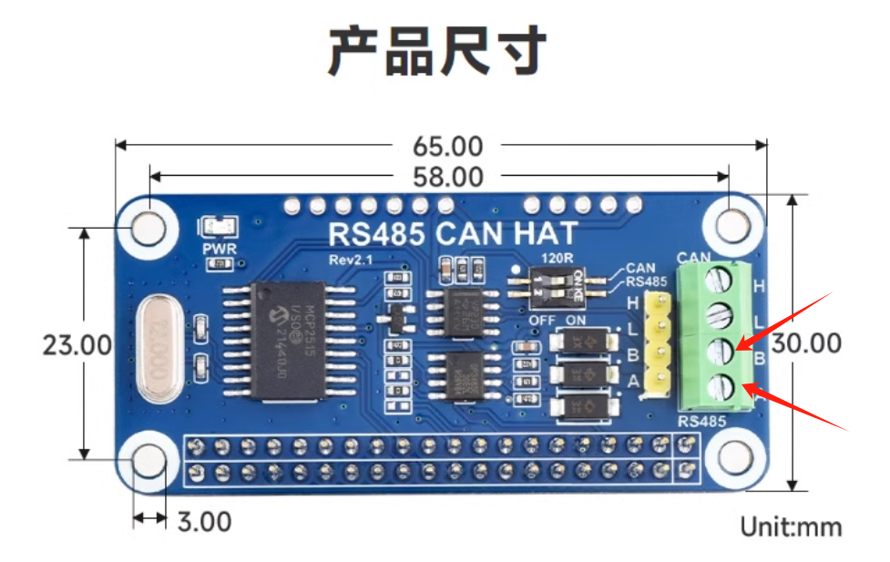
该拓展板485支持自动切换收发状态,无需程序控制,只需将拓展板的8、10脚与M4-R1的40PIN的8、10脚相连,然后将485设备接上拓展板的A、B进行收发即可。
TOOL
Edit this page on GitHub
Last Updated:
Contributors: zwhuang
Prev
WIFI&BT