第六章 APP 稳定性测试
1. 概述
自动化测试框架arkxtest,是工具集的重要组成部分,支持 JS/TS 语言的单元测试框架(JsUnit)及 UI 测试框架(UiTest)。JsUnit提供单元测试用例执行能力,提供用例编写基础接口,生成对应报告,用于测试系统或应用接口。UiTest通过简洁易用的API提供查找和操作界面控件能力,支持用户开发基于界面操作的自动化测试脚本。本指南介绍了测试框架的主要功能、实现原理、环境准备,以及测试脚本编写和执行等内容。
2. 环境准备
环境要求自动化脚本的编写主要基于 DevEco Studio,建议使用 3.0 之后的版本。脚本执行需要 PC 连接硬件设备。
脚本执行需要PC连接板卡硬件设备
搭建环境DevEco Studio 可参考 03 - 开发环境准备章节介绍进行下载,并进行相关配置。
3. 新建和编写测试脚本
新建测试脚本在DevEco Studio中新建应用开发工程,其中ohos目录即为测试脚本所在的目录。在工程目录下打开待测试模块下的ets文件,将光标置于代码中任意位置,单击右键 > Show Context Actions > Create Ohos Test或快捷键Alt+enter > Create Ohos Test创建测试类,更多指导请参考DevEco Studio中指导。
4. 编写单元测试脚本
注意
本章节主要描述单元测试框架支持能力,以及能力的使用方法。
在单元测试框架,测试脚本需要包含如下基本元素:
依赖导包,以便使用依赖的测试接口。
测试代码编写,主要编写测试代码的相关逻辑,如接口调用等。
断言接口调用,设置测试代码中的检查点,如无检查点,则不可认为一个完整的测试脚本。
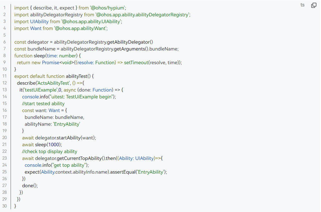
如下示例代码实现的场景是:启动测试页面,检查设备当前显示的页面是否为预期页面。
5. 编写UI测试脚本
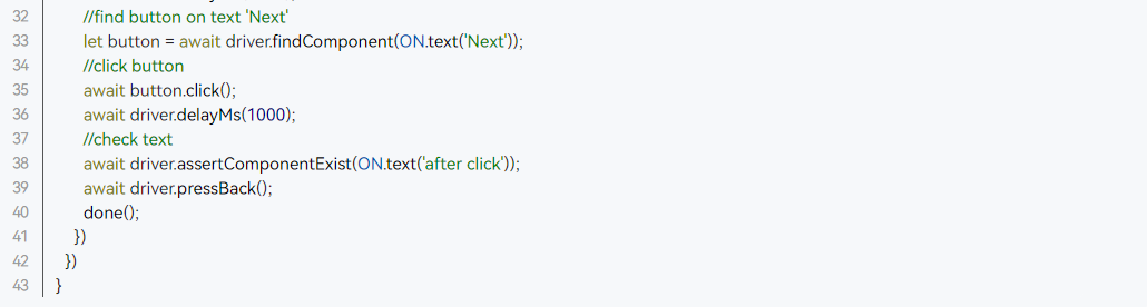
本章节主要介绍UI测试框架支持能力,以及对应能力API的使用方法。UI测试基于单元测试,UI测试脚本在单元测试脚本上增加了对UiTest接口(提供链接)调用,进而完成对应的测试活动。如下的示例代码是在上面的单元测试脚本基础上增量编写,实现的是在启动的应用页面上进行点击操作,然后检测当前页面变化是否为预期变化。
1)增加依赖导包import { Driver, ON } from '@ohos.UiTest'
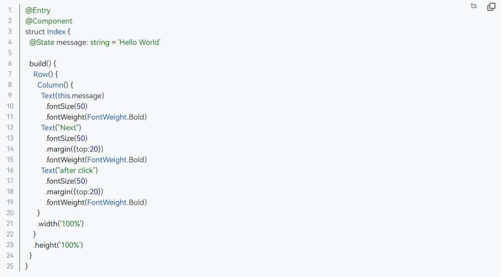
2)编写index.ets页面代码
3)编写具体测试代码

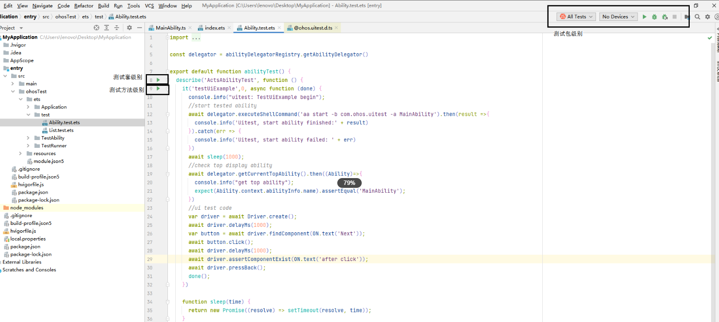
4)执行测试脚本 DevEco Studio执行通过点击按钮执行,当前支持以下执行方式:
测试包级别执行,即执行测试包内的全部用例。
测试套级别执行,即执行describe方法中定义的全部测试用例。
测试方法级别执行,即执行指定it方法也就是单条测试用例。
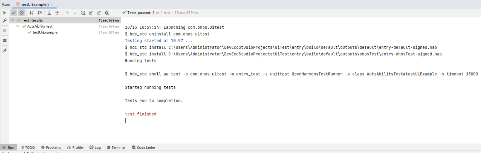
查看测试结果
测试执行完毕后可直接在DevEco Studio中查看测试结果,如下图示例所示:
6. 常见问题
单元测试用例常见问题
错误 1
用例中增加的打印日志在用例结果之后才打印
问题描述
用例中增加的日志打印信息,没有在用例执行过程中出现,而是在用例执行结束之后才出现。
可能原因
此类情况只会存在于用例中有调用异步接口的情况,原则上用例中所有的日志信息均在用例执行结束之前打印。
解决方法
当被调用的异步接口多于一个时,建议将接口调用封装成Promise方式调用。
错误 2
执行用例时报error:fail to start ability
问题描述
执行测试用例时候,用例执行失败,控制台返回错误:fail to start ability。
可能原因
测试包打包过程中出现问题,未将测试框架依赖文件打包在测试包中。
解决方法
检查测试包中是否包含OpenHarmonyTestRunner.abc文件,如没有则重新编译打包后再次执行测试。
错误 3
执行用例时报用例超时错误
问题描述
用例执行结束,控制台提示execute time XXms错误,即用例执行超时
可能原因
用例执行异步接口,但执行过程中没有执行到done函数,导致用例执行一直没有结束,直到超时结束。
用例调用函数耗时过长,超过用例执行设置的超时时间。
用例调用函数中断言失败,抛出失败异常,导致用例执行一直没有结束,直到超时结束。
解决方法
检查用例代码逻辑,确保即使断言失败场景认可走到done函数,保证用例执行结束。
可在IDE中Run/Debug Configurations中修改用例执行超时配置参数,避免用例执行超时。
检查用例代码逻辑,断言结果,确保断言Pass。
UI测试用例常见问题
错误 1
失败日志有“Get windows failed/GetRootByWindow failed”错误信息
问题描述
UI测试用例执行失败,查看hilog日志发现日志中有“Get windows failed/GetRootByWindow failed”错误信息。
可能原因
系统ArkUI开关未开启,导致被测试界面控件树信息未生成。
解决方法
执行如下命令,并重启设备再次执行用例。
	hdc shell param set persist.ace.testmode.enabled 1
	shell
	hdc shell param set persist.ace.testmode.enabled 1
错误 2
失败日志有“uitest-api dose not allow calling concurrently”错误信息
问题描述
UI测试用例执行失败,查看hilog日志发现日志中有“uitest-api dose not allow calling concurrently”错误信息。
可能原因
用例中UI测试框架提供异步接口没有增加await语法糖调用。
多进程执行UI测试用例,导致拉起多个UITest进程,框架不支持多进程调用。
解决方法
检查用例实现,异步接口增加await语法糖调用。
避免多进程执行UI测试用例。
错误 3
失败日志有“does not exist on current UI! Check if the UI has changed after you got the widget object”错误信息
问题描述
UI测试用例执行失败,查看hilog日志发现日志中有“does not exist on current UI! Check if the UI has changed after you got the widget object”错误信息。
可能原因
在用例中代码查找到目标控件后,设备界面发生了变化,导致查找到的控件丢失,无法进行下一步的模拟操作。
解决方法
重新执行UI测试用例。