Burning Guide
1 Download the Titan burning tool
Windows version:
https://cloud.spacemit.com/prod-api/release/download/tools?token=titantools_for_windows_X86_X64
Linux version:
https://cloud.spacemit.com/prod-api/release/download/tools?token=titantools_for_linux_64BIT_APPIMAGE
2 Installation
2.1 PC Configuration Requirements
Operating system: Windows or Linux C drive space (or Linux system Home space): > 10GB
2.2 Windows Installation
Take Windows 11 as an example.
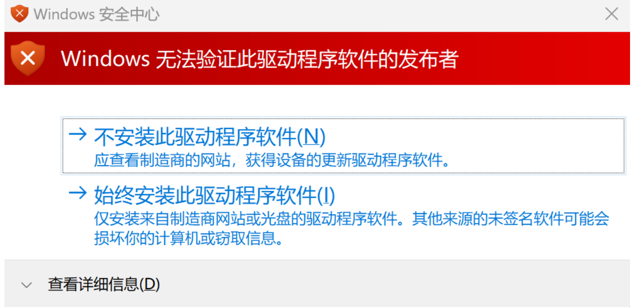
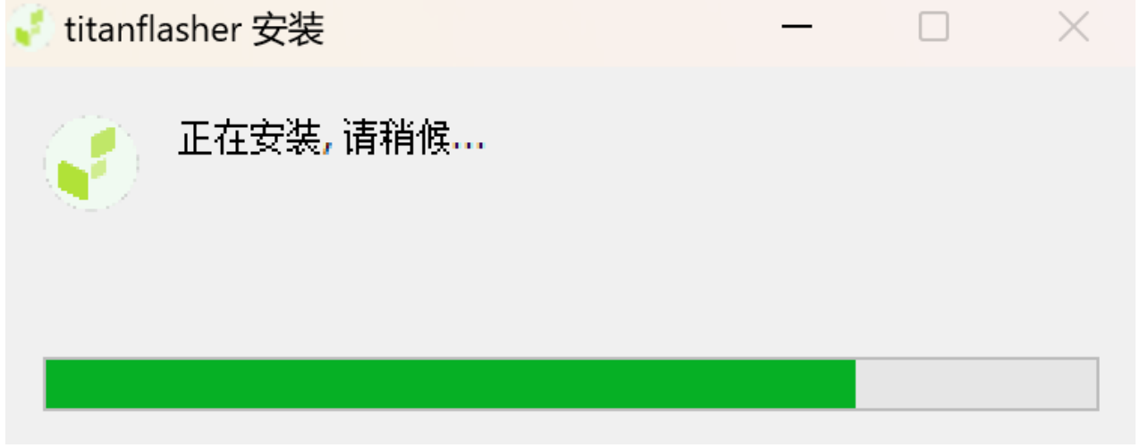
Download the latest version of the flash tool titantools_for_windows.exe and double-click titantools_for_windows_last to install; If the system prompts Do you want to allow this app from an unknown publisher to make changes to your device?, select Yes; If the system prompts that Windows cannot verify the publisher of this driver software, select Always install this driver software;
If you are prompted with Do you want to allow this app from an unknown publisher to make changes to your device?, select Yes. Wait until the installation is complete.
2.3 Installation on Linux
Take Ubuntu as an example.
- Download the latest version of the flash tool titantools_for_linux.AppImage 2) Grant executable permissions 3) Double-click to start using, no installation required
Note: If the startup fails with an error: "dlopen(): error loading libfuse.so.2" you can install libfuse dependencies:
sudo apt install libfuse23. Function Introduction
3.1.1 Tool Home Page
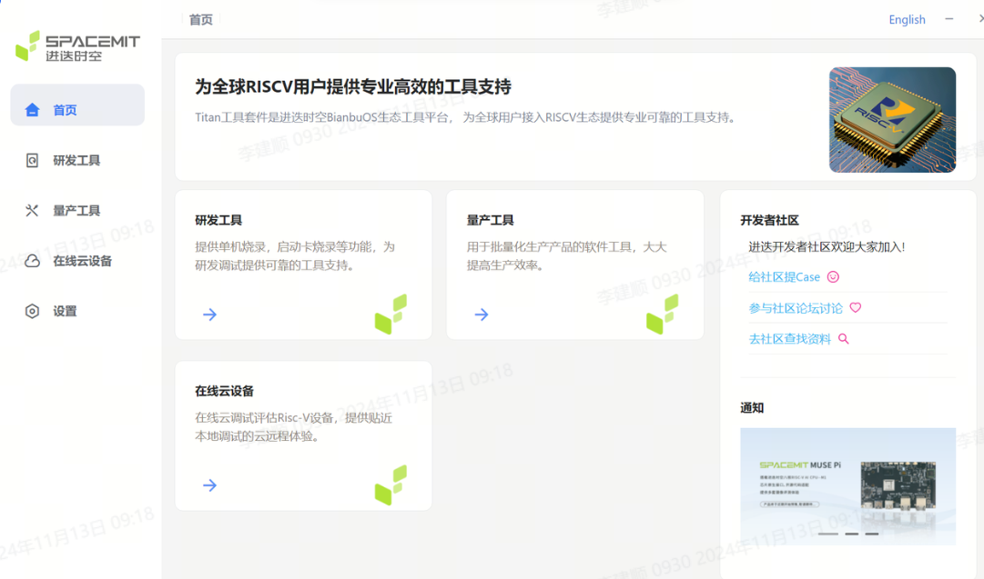
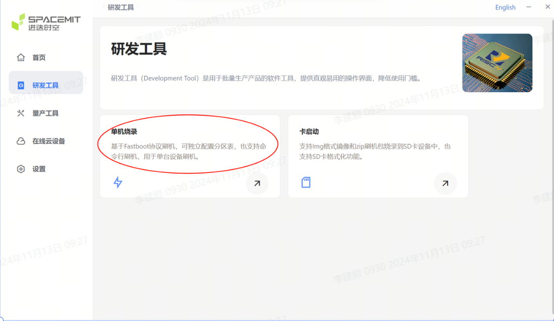
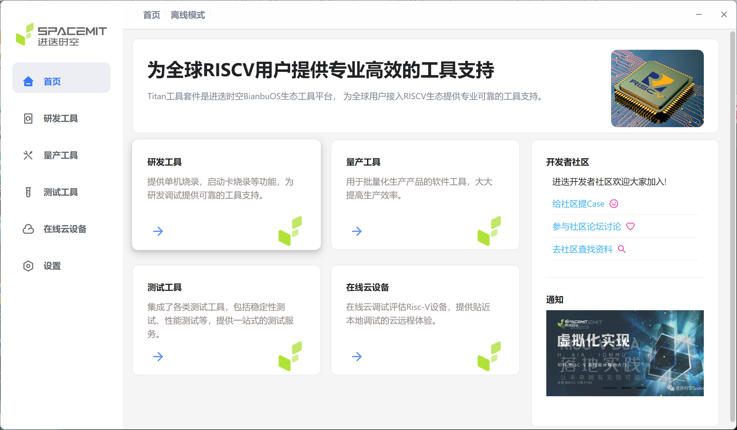
Open the flashing tool. If the system prompts Do you want to allow this app from an unknown publisher to make changes to your device?, select Yes. The homepage displays four main functional modules: R&D tools, mass production tools, testing tools, and online cloud devices. Clicking on different tool modules will jump to the corresponding page.
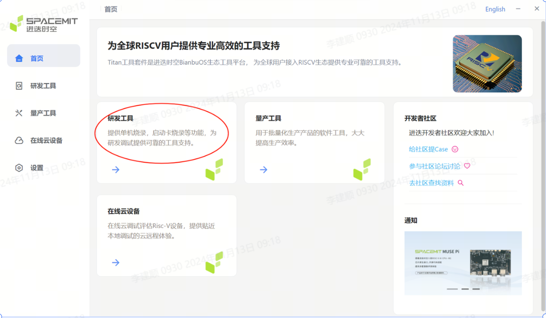
3.1.2 R&D tool module
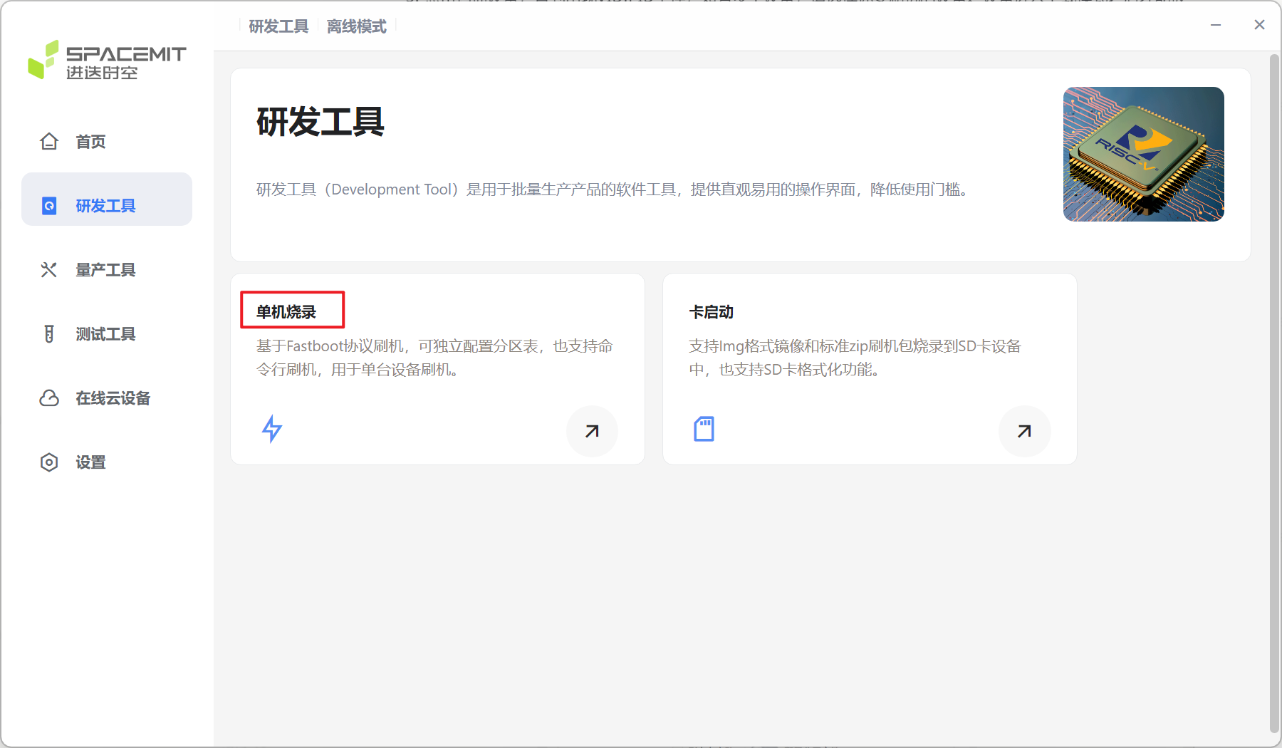
Click R&D Tools on the home page to jump to the R&D Tools interface.
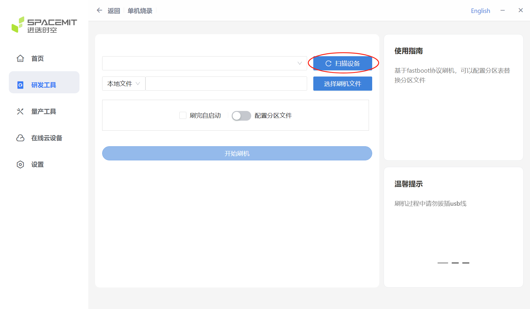
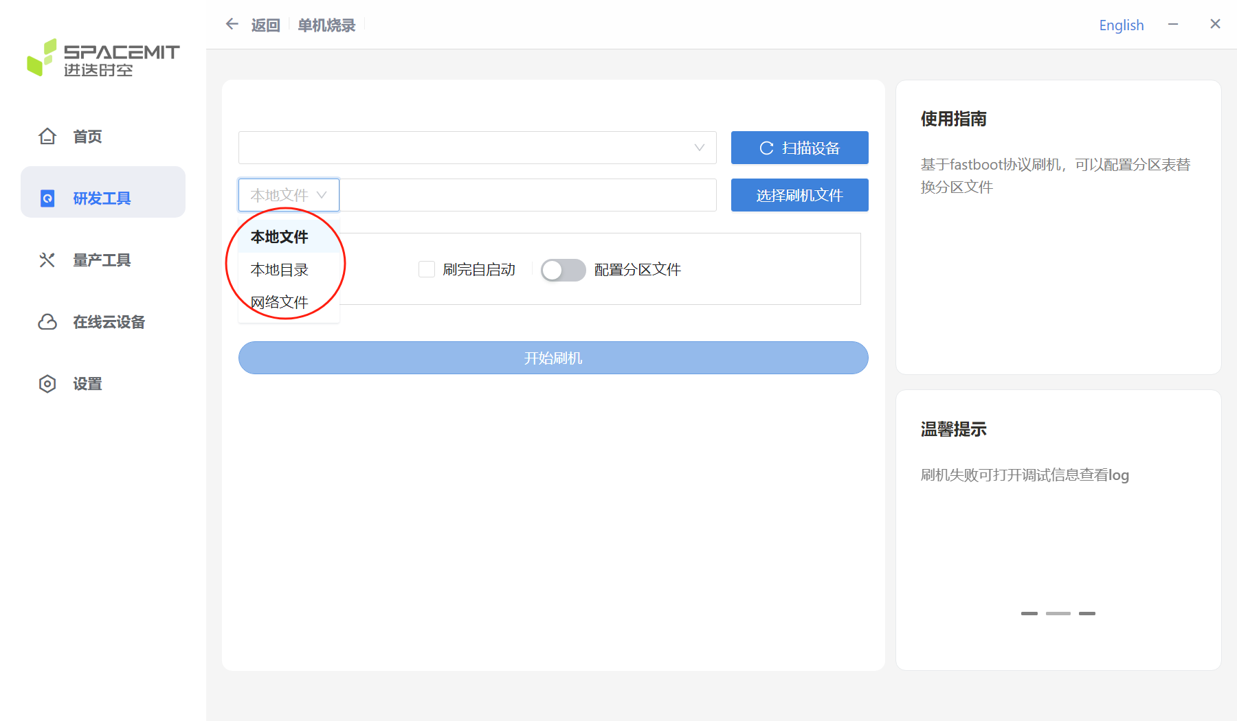
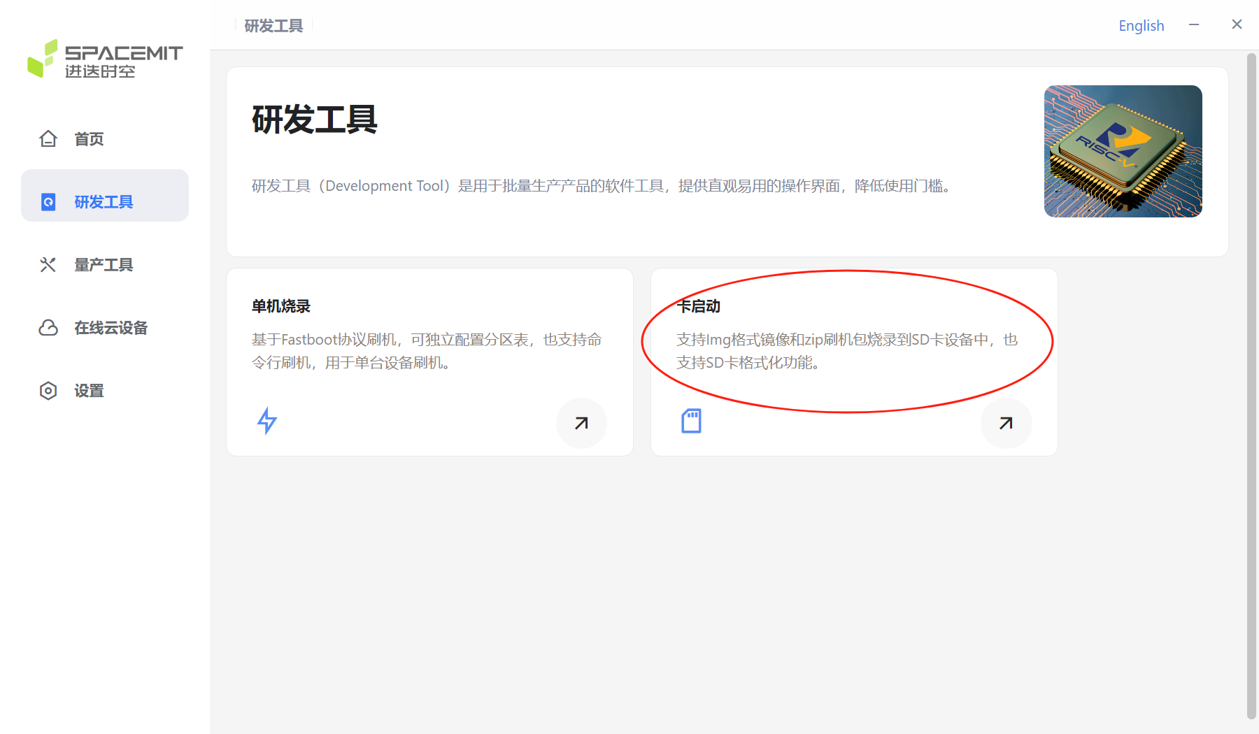
Stand-alone burning There are stand-alone burning options and card boot options on the R&D tool page. Select the stand-alone burning option here.
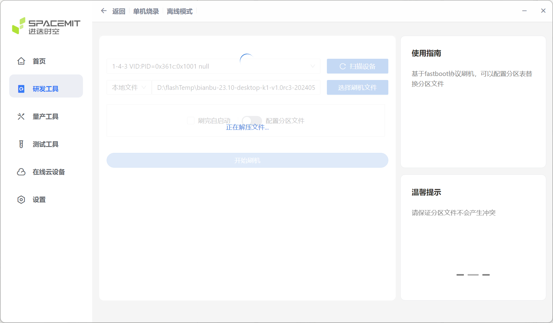
Click Scan Device on the R&D Tool interface. Note: Before scanning the device, make sure the device is in flash mode, otherwise the scan will fail.
When the device is successfully scanned, a flash serial number similar to the figure below will appear.

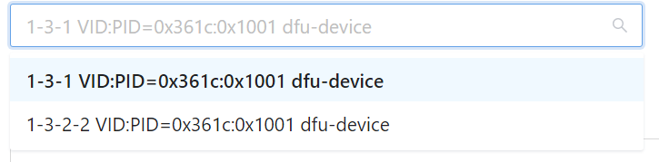
If there are multiple devices, click the drop-down button to select the device.
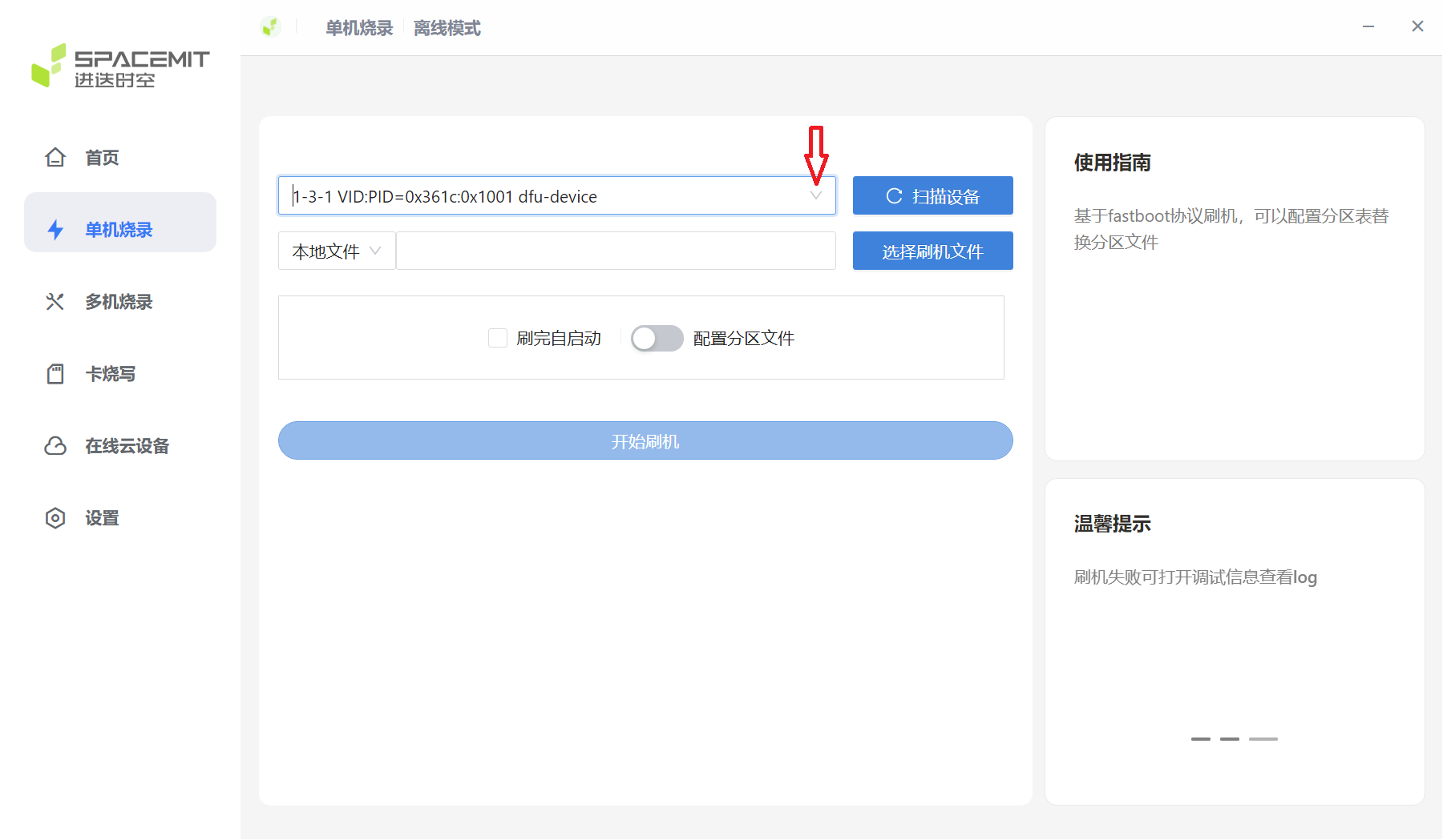
Select the corresponding USB device
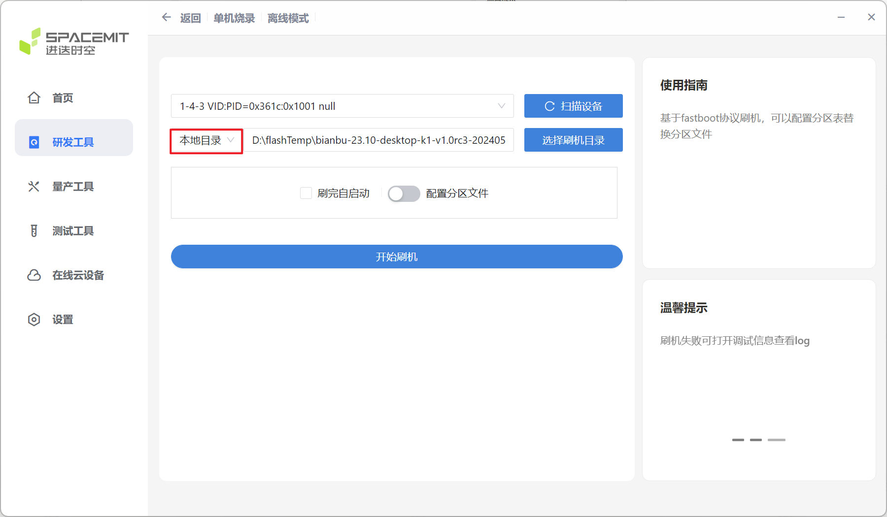
After the device is identified, you can select the file path source by pulling down the image selection position. You can select local files, local directories, and network files.
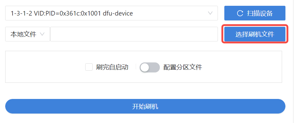
Click Select Flash File, select the firmware, and then the tool prompts that the file is being extracted..., wait patiently for it to complete.
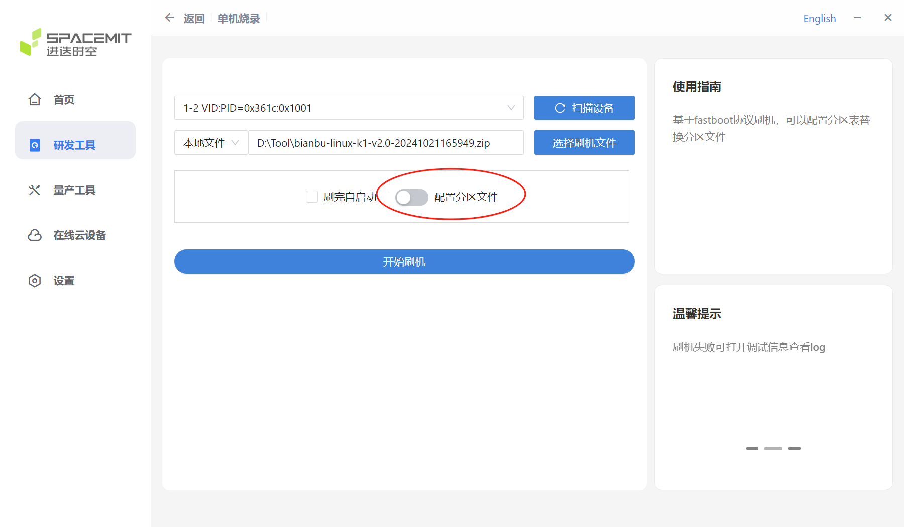
(If you need to configure partitions, please refer to section 1.3.4)
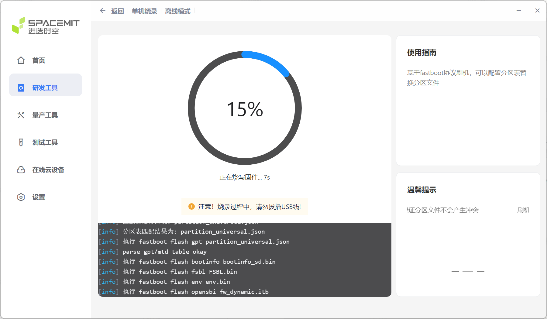
Click Start Flashing to start the flashing process.
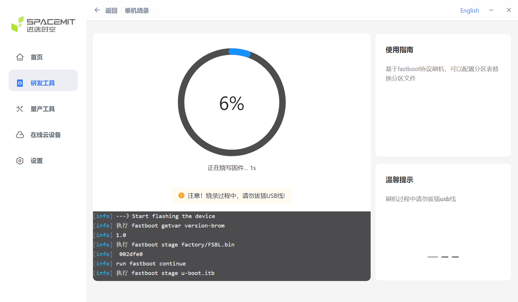
After the flashing is completed, you can enter the system by powering on again. Card boot Click the card boot option in the R&D tool interface to enter the card boot interface.
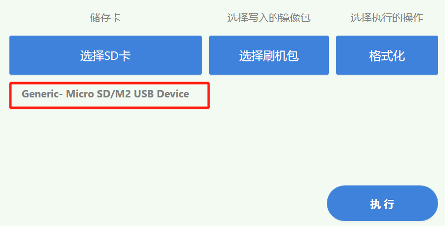
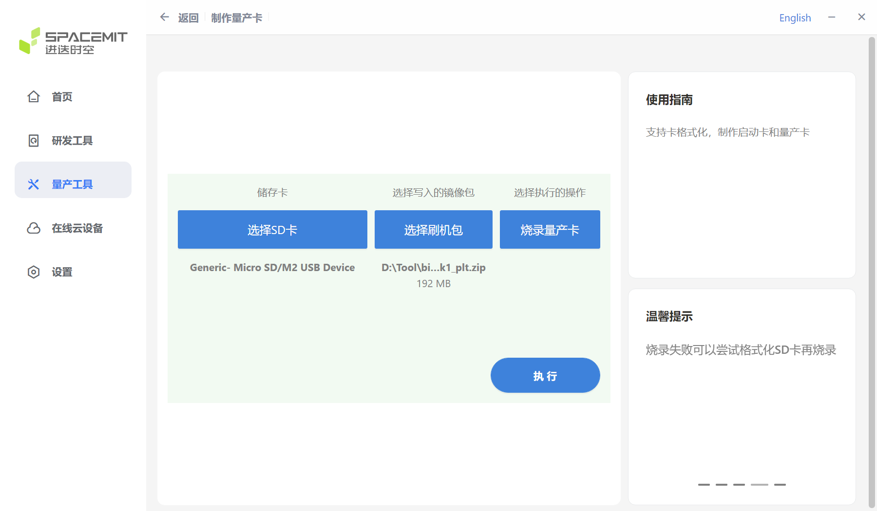
Click to select SD card on the card boot page. Note: Before card booting, the computer needs to be inserted with SD card.

After clicking to select SD card, the following interface will pop up, select SD card.
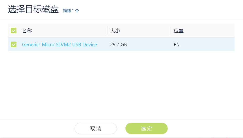
After selecting the SD card, the name of the selected SD card will be displayed in the position below the picture.
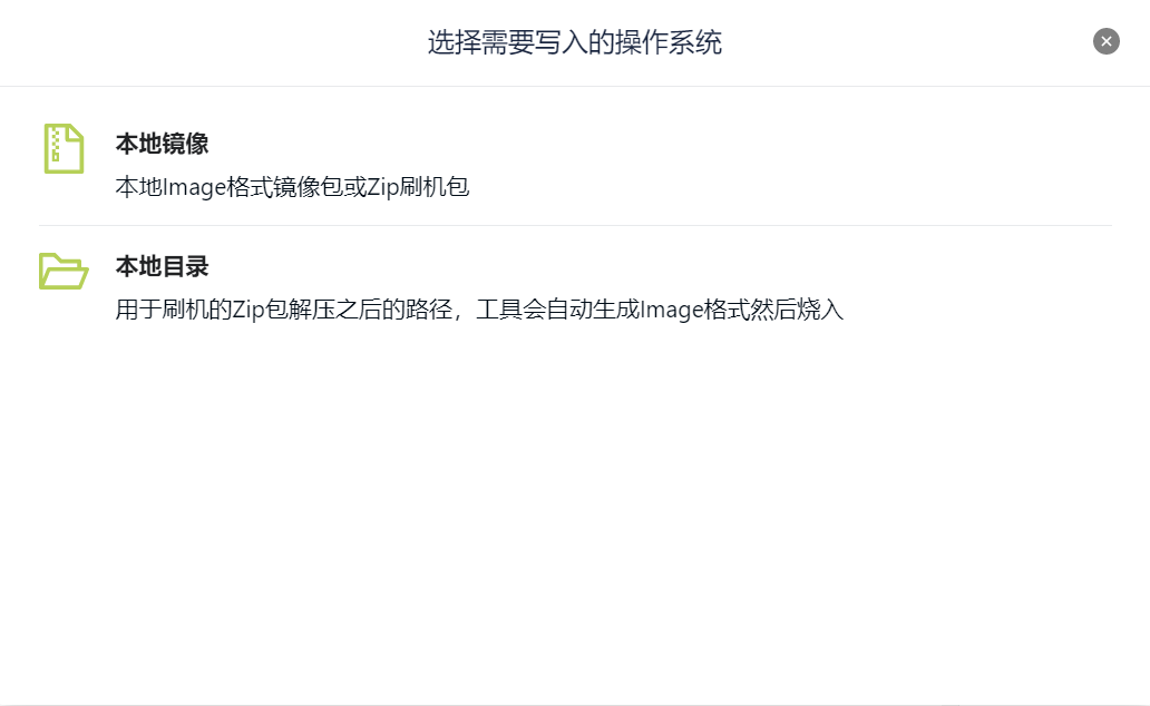
After selecting the SD card, click Select Flashing Package to pop up the options shown below and select the flashing package path.
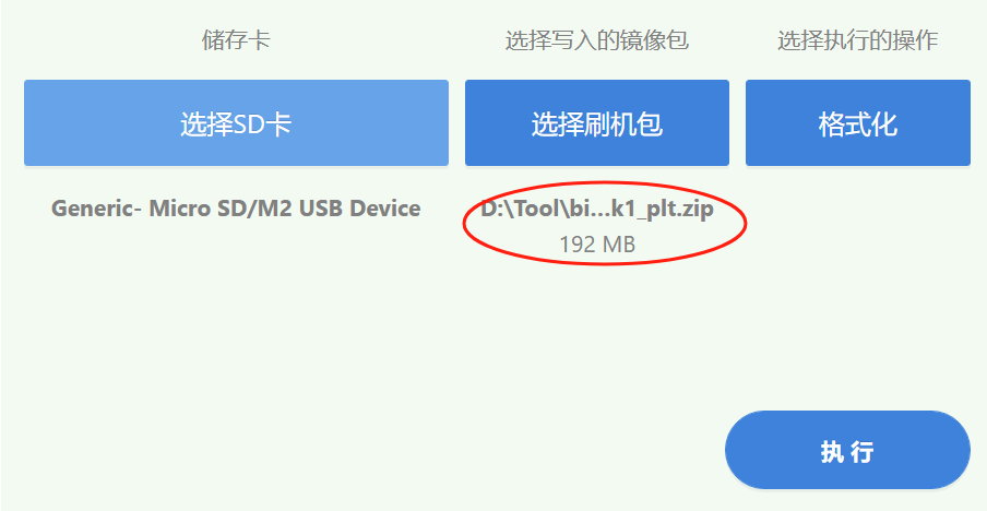
After selecting the flashing package, the flashing package path and name will be displayed in the picture below.
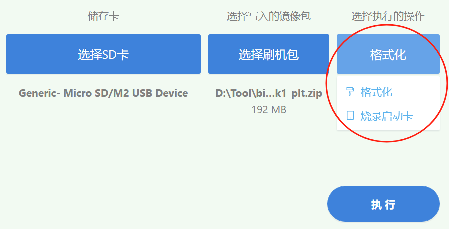
After selecting the flash package, select the operation you need to perform in the position shown below. The default selection is to burn the startup card. (Note: You need to format the SD card before burning the startup card. Please back it up in advance to avoid data loss)
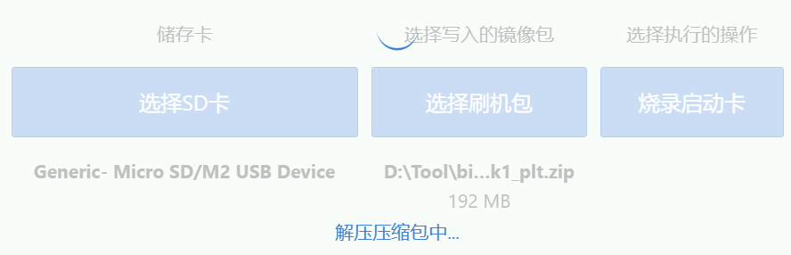
After clicking Execute, the following window will pop up. After clicking OK, wait for the decompression of the compressed package to complete.
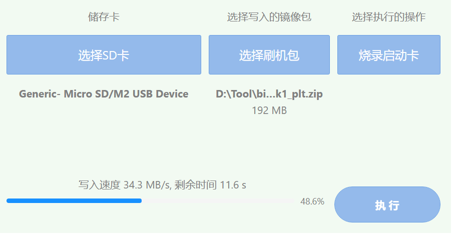
After decompression, start burning and wait for the burning to end.
3.2 Configuring Partitions
After selecting the burning device and burning the firmware, you can configure the partition file as needed.
After opening the configuration partition file, the following window will pop up, where you can select or replace the corresponding partition file.
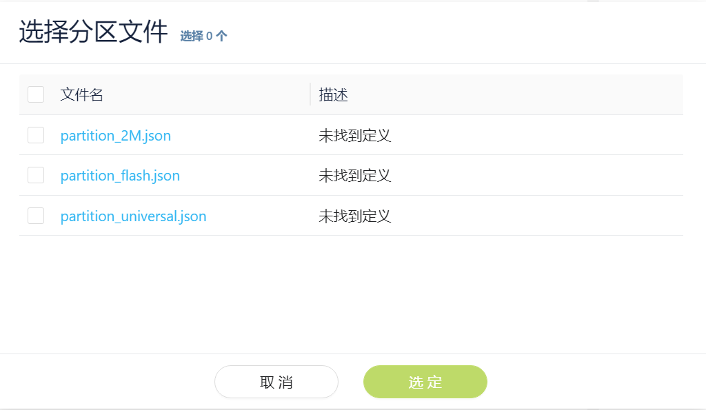
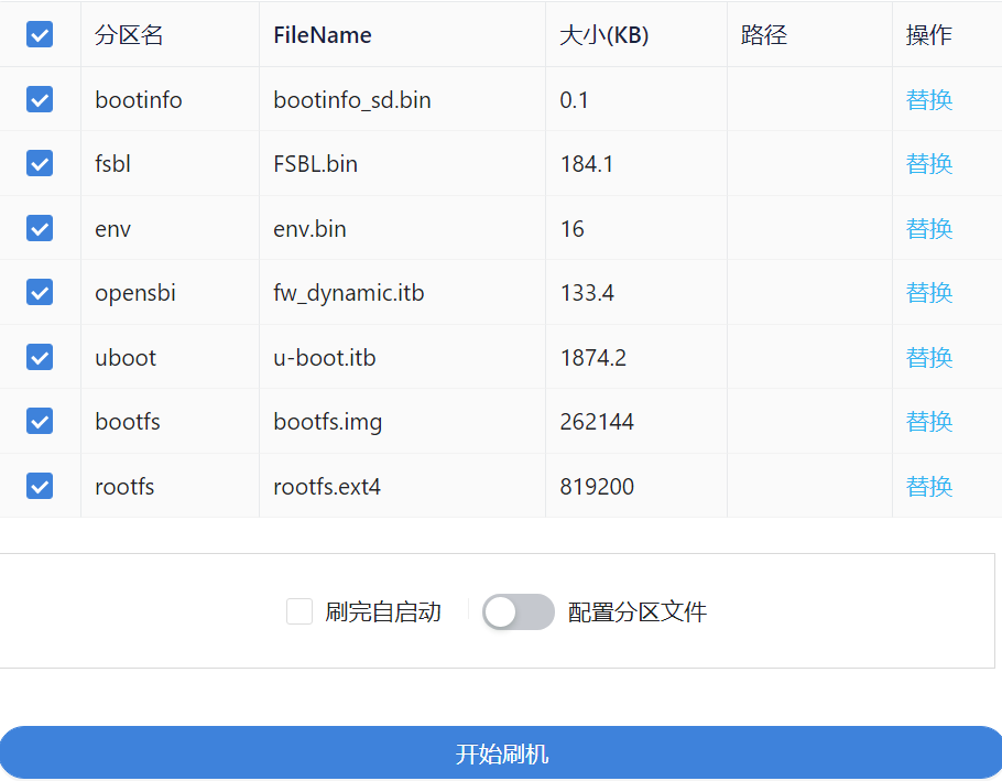
After selecting the partition file, the following content will appear. (Note: If you select different partition files, the corresponding partition names will be different. Please make sure that the partition files do not conflict.)
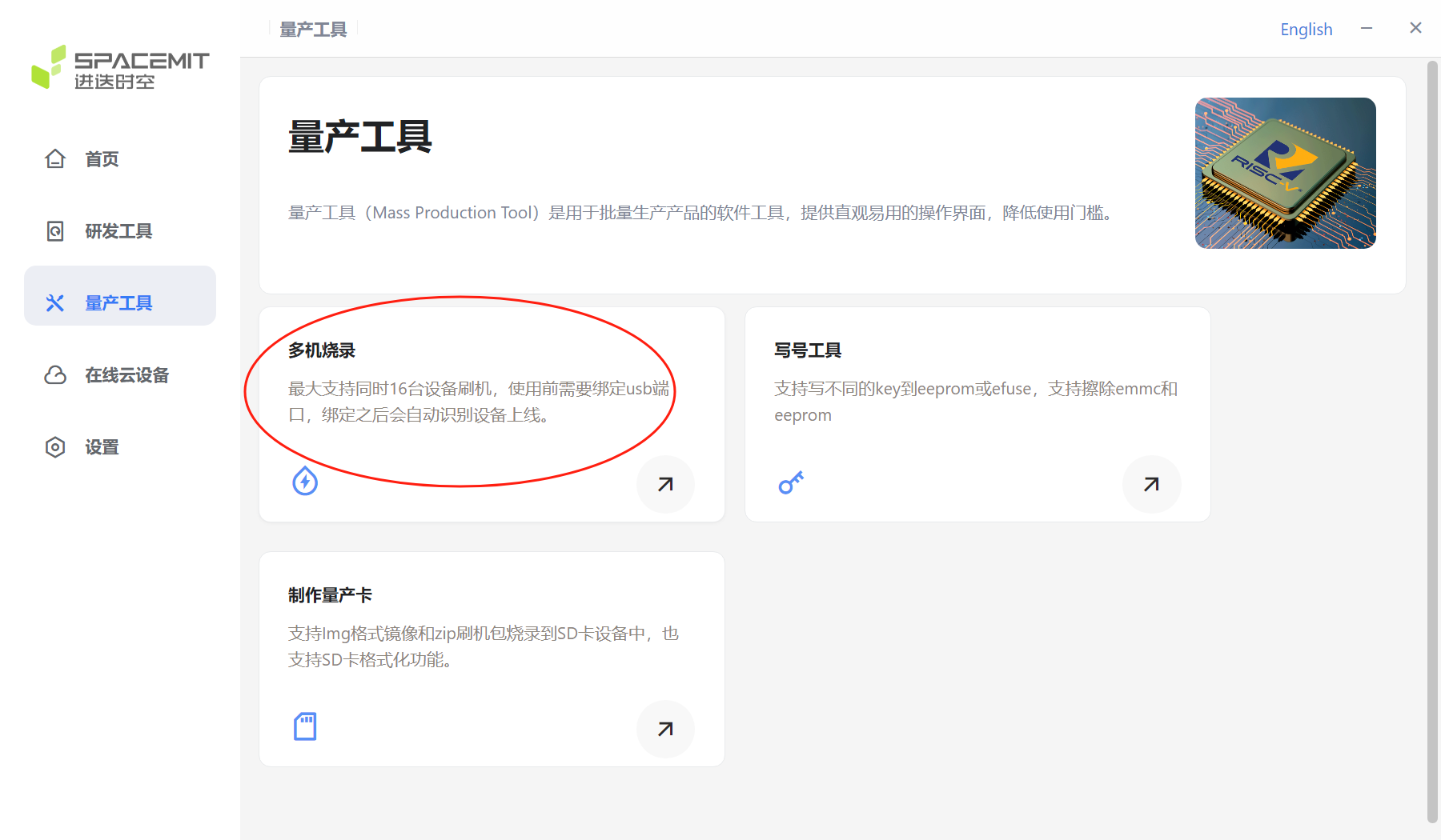
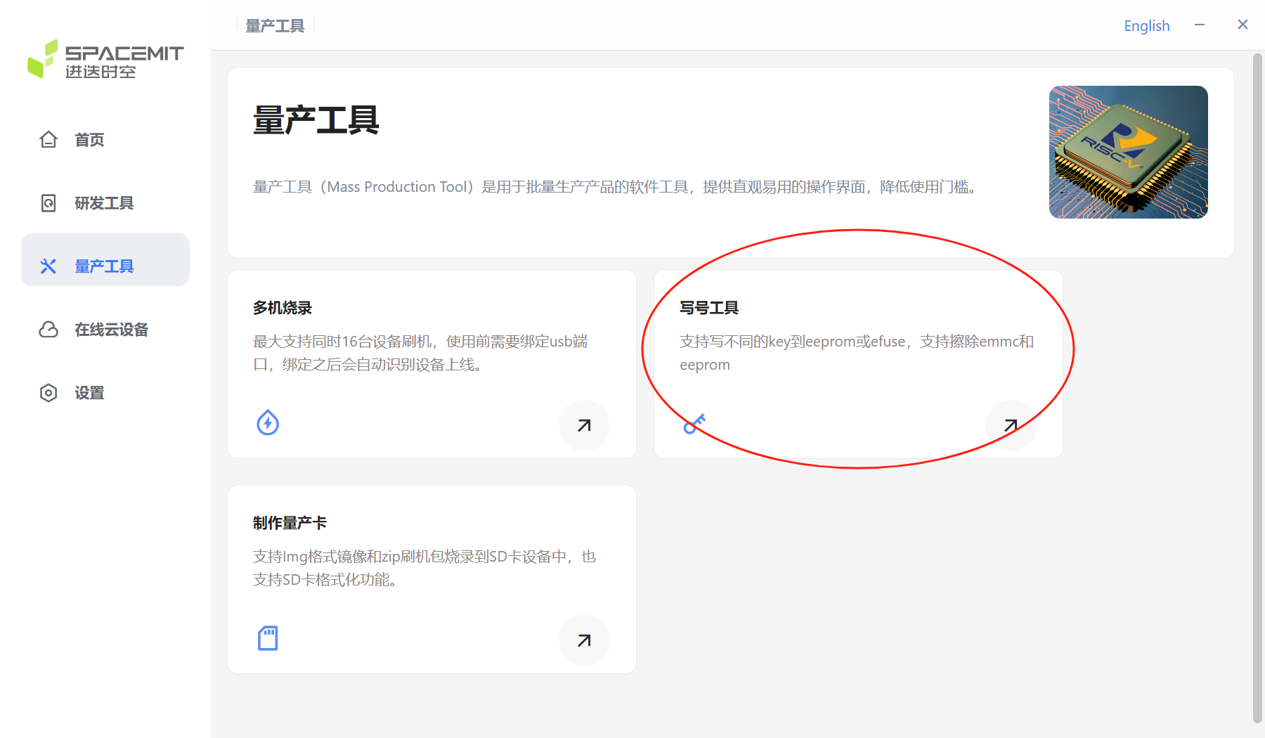
3.3 Mass production tool module
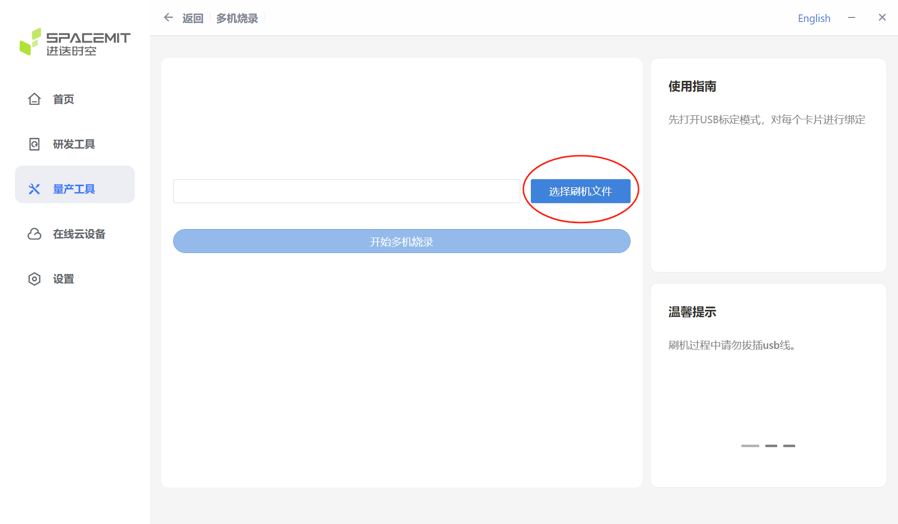
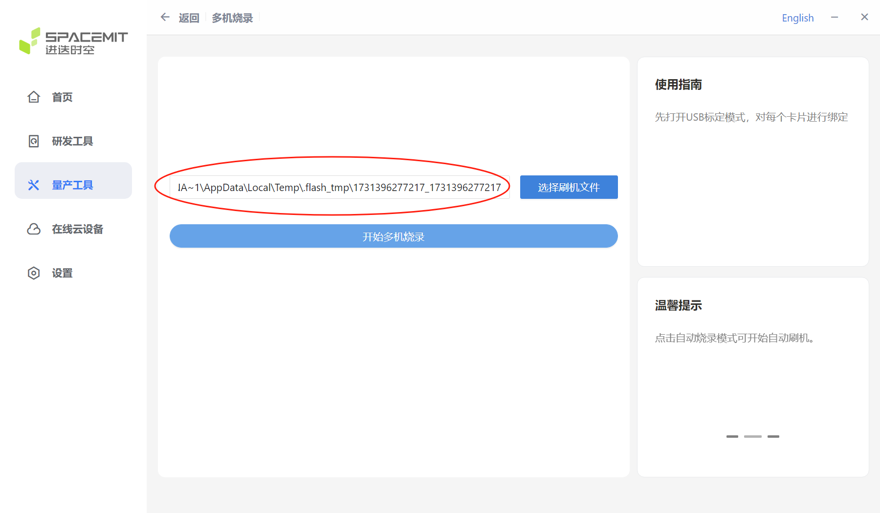
Multi-machine burning Click to enter the mass production tool page and select multi-machine burning. Note: Multi-machine burning mode only supports zip files.
Select Multi-device Burning, then Flash Firmware.
After selecting the flash file and decompressing it, the decompressed file path will be displayed in the figure below.
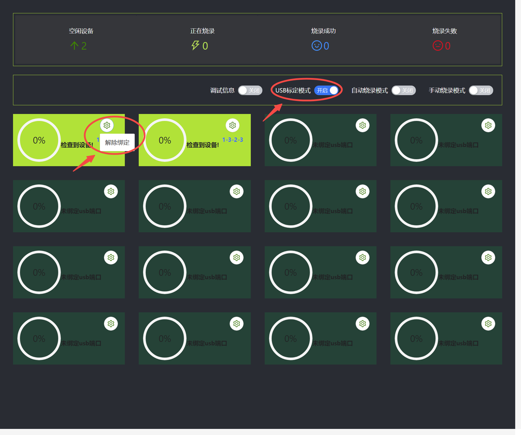
After clicking Start Multi-device Burning, the Multi-device Burning window will pop up. Enable USB calibration mode and bind the USB port.
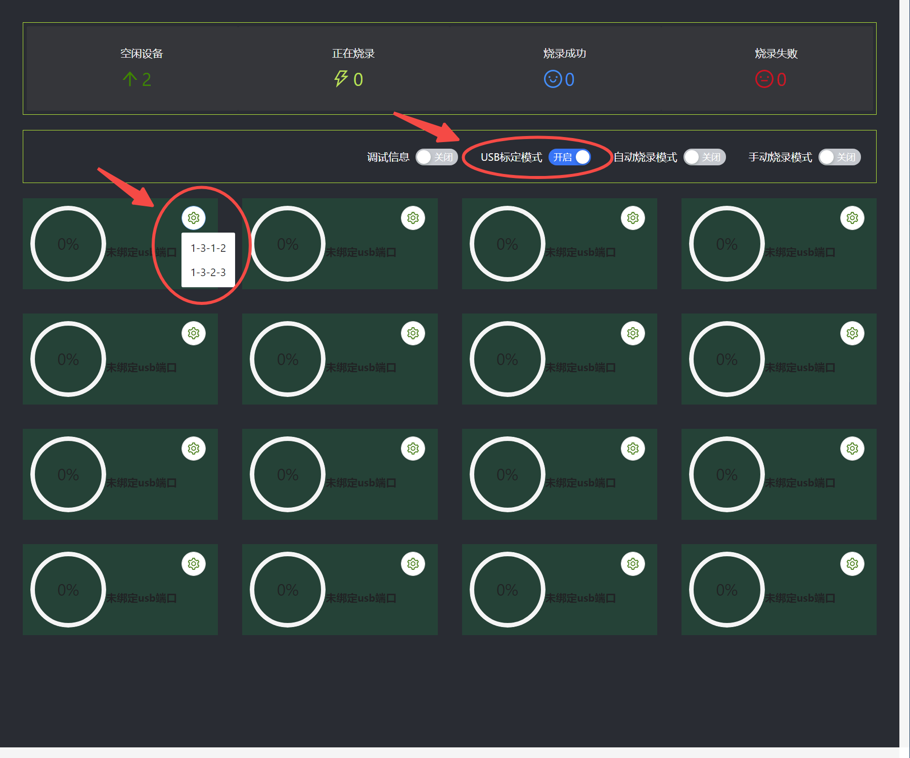
After the binding is completed, the corresponding USB number will be displayed below.
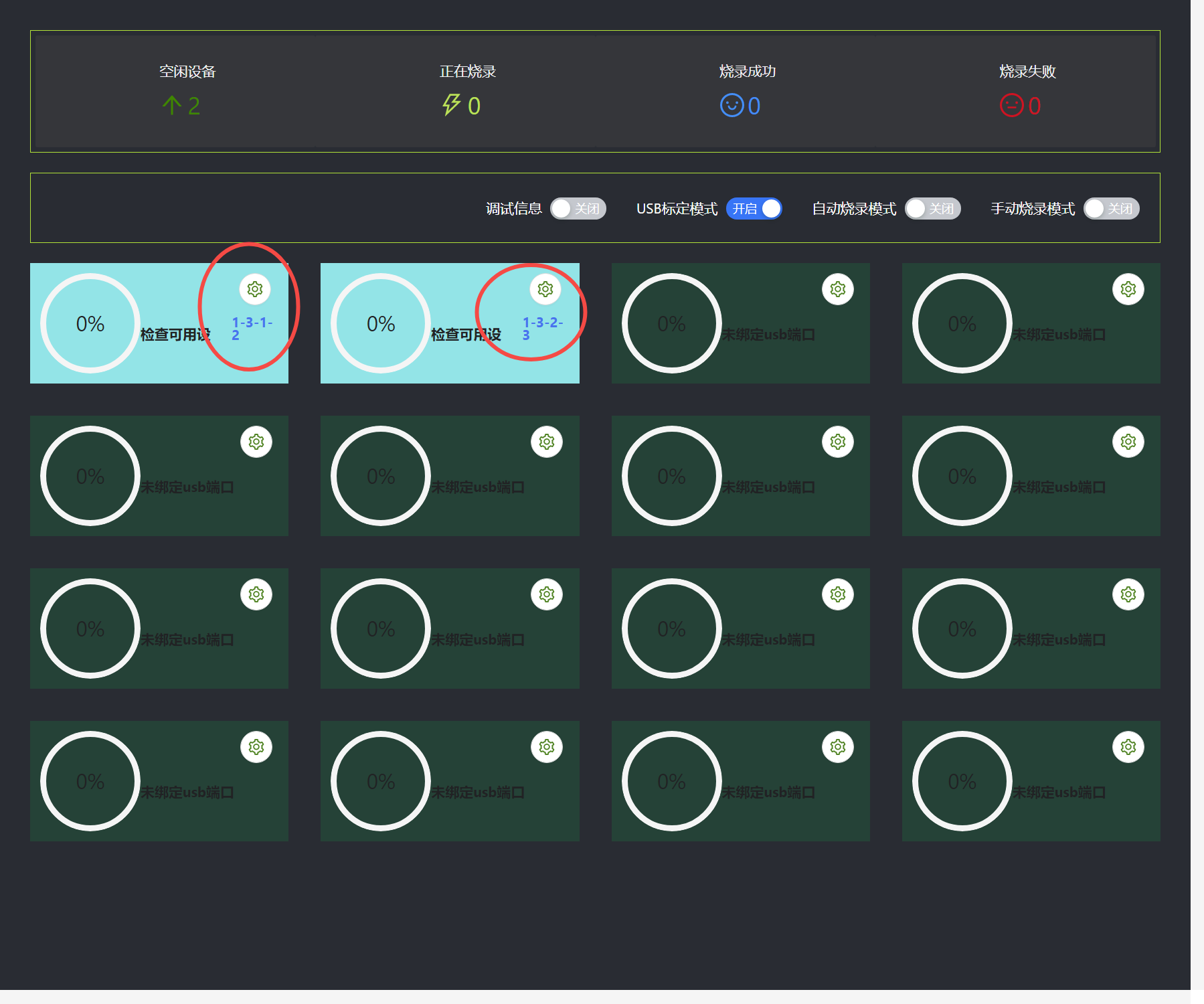
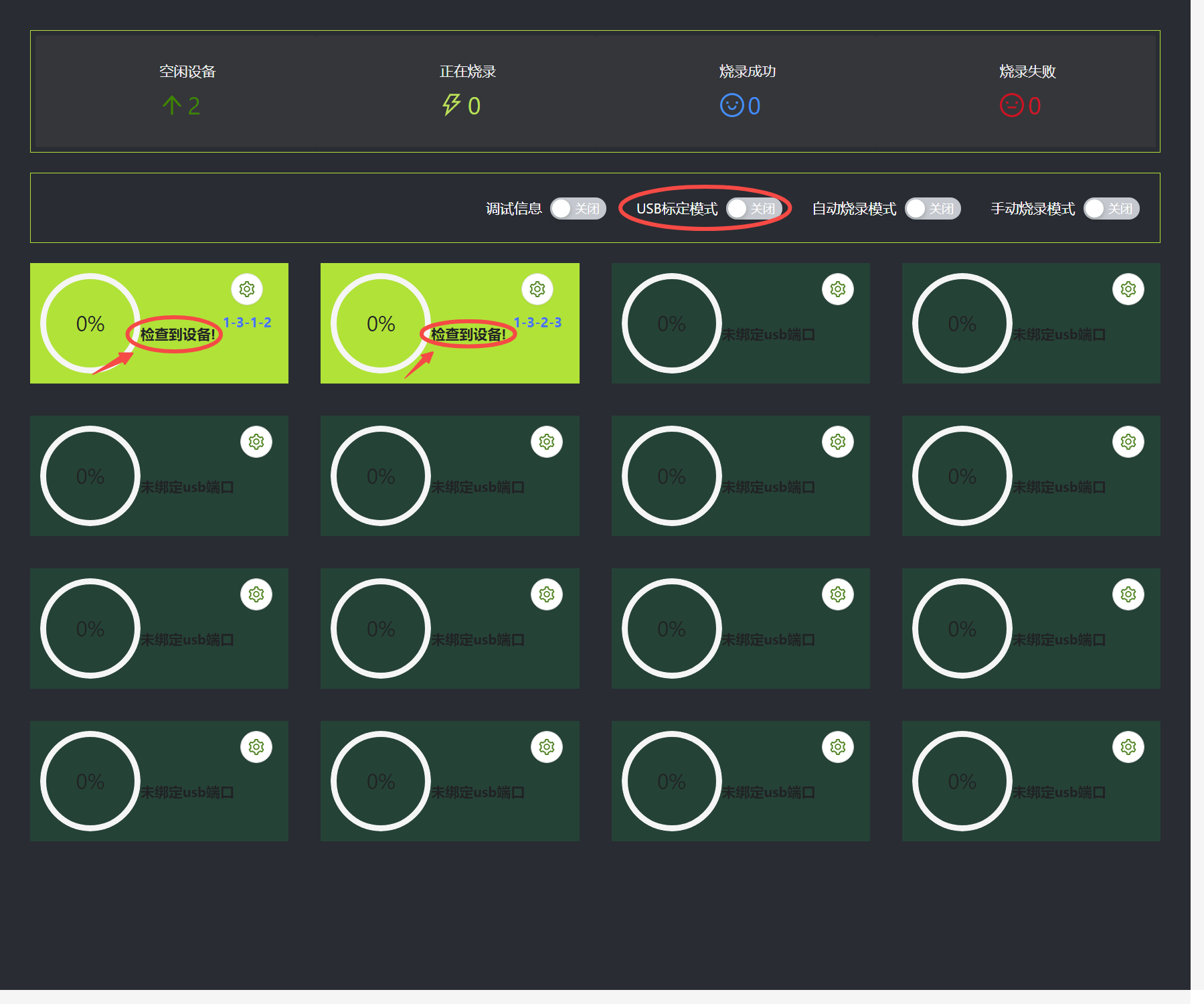
After USB binding, turn off the USB calibration mode and wait for the device to be detected. The USB calibration mode can calibrate the USB number of the device to detect the corresponding USB burning status.
If you need to unbind and reopen the USB calibration mode, just click the button in the picture below. After unbinding, you can recalibrate.
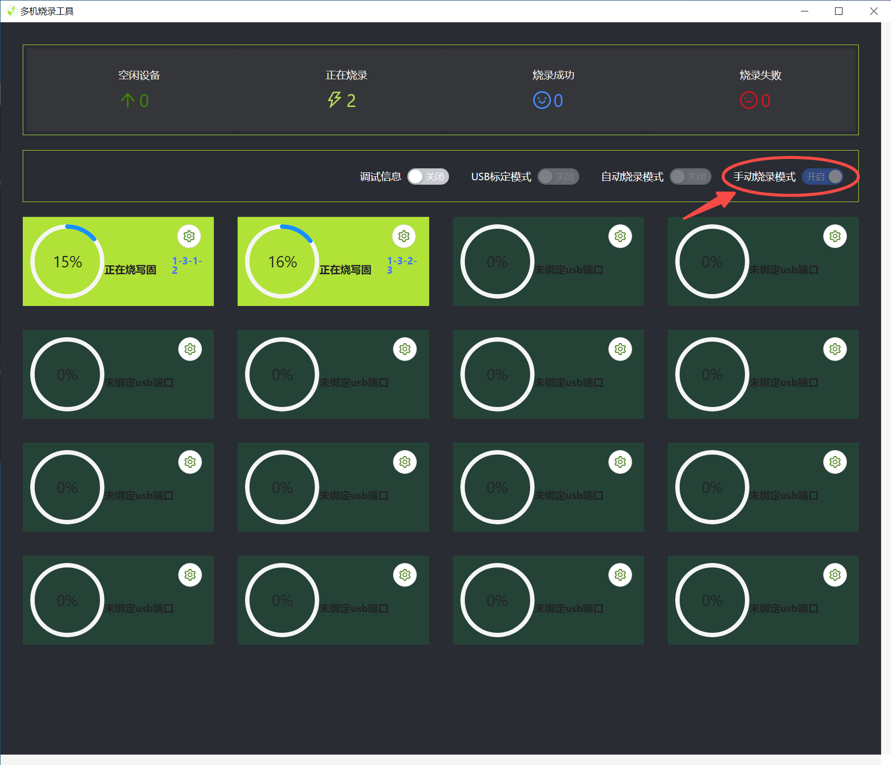
Turn off USB calibration mode, select automatic burning or manual burning, and wait for the device to burn. Note:
Automatic burning mode means: if the current device is burned after completion, without changing the USB, continue to use the USB number to connect a new device to continue burning the firmware.
Manual burning mode means: after the current device is burned, manually control whether to continue burning the firmware.
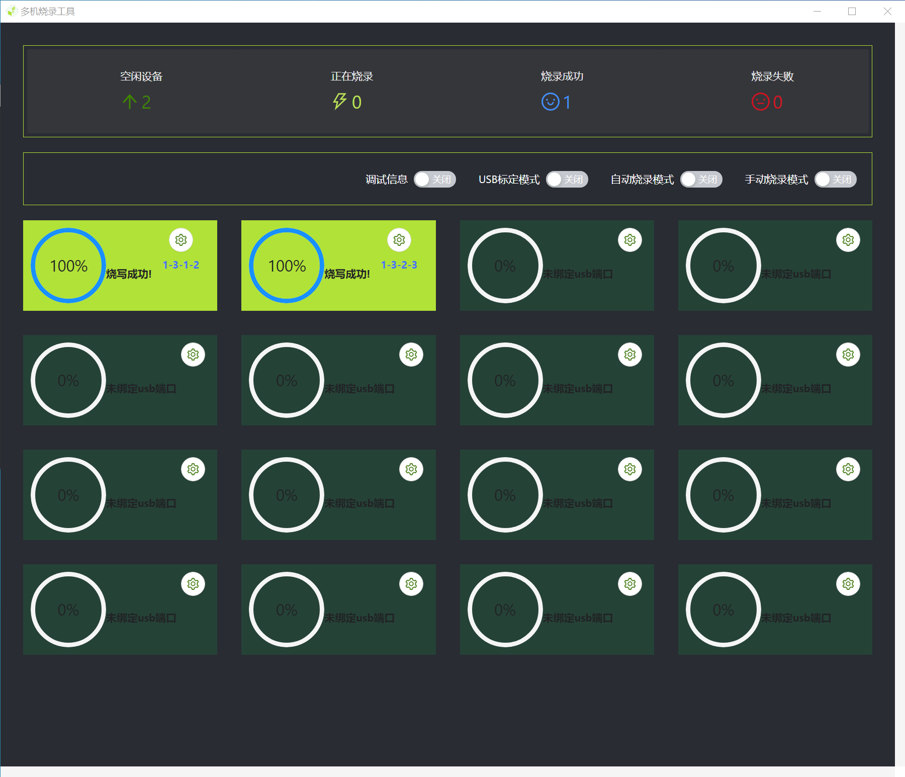
When burning is complete, close the window.
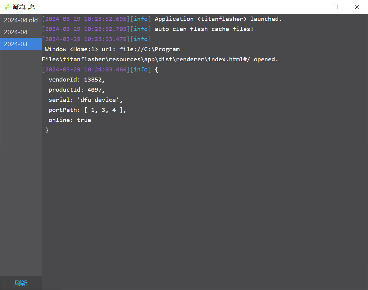
If you turn on the debug information option, the following window will appear.
Make mass production cards
3.4 Number Writing Tools
Click on the mass production tool and select "Writing Tool"
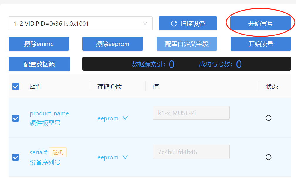
Click Scan Device to successfully identify the device serial number
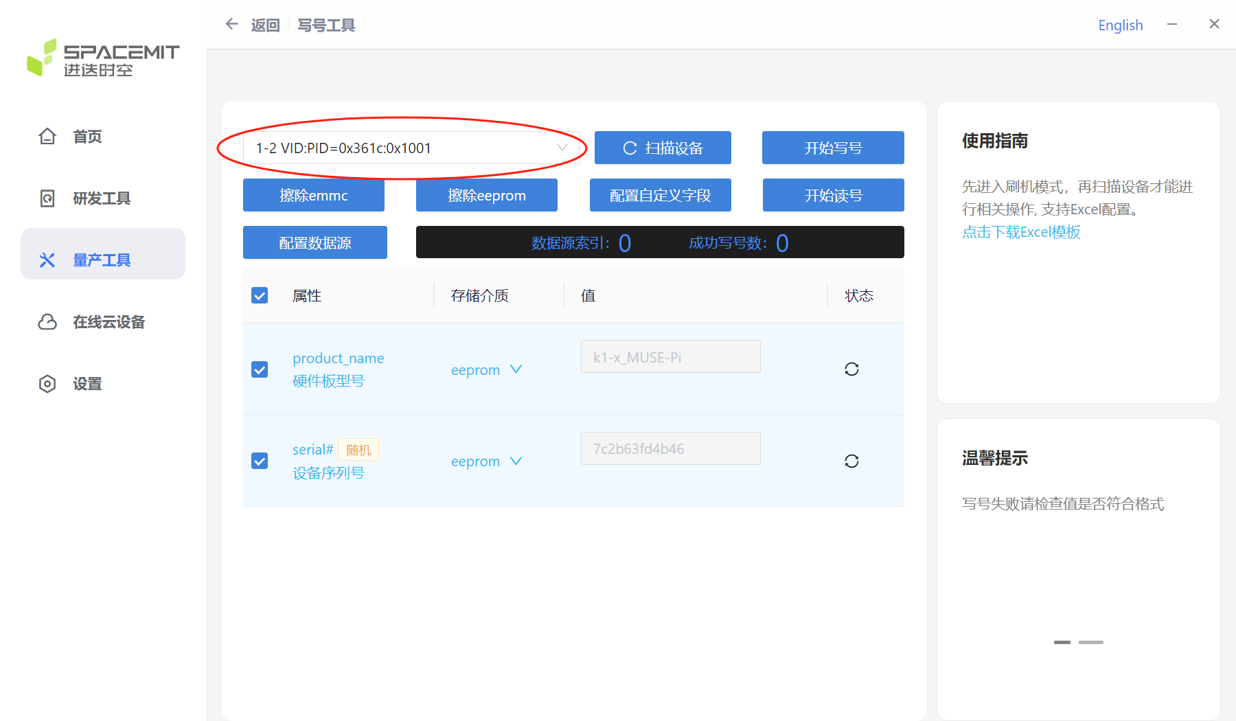
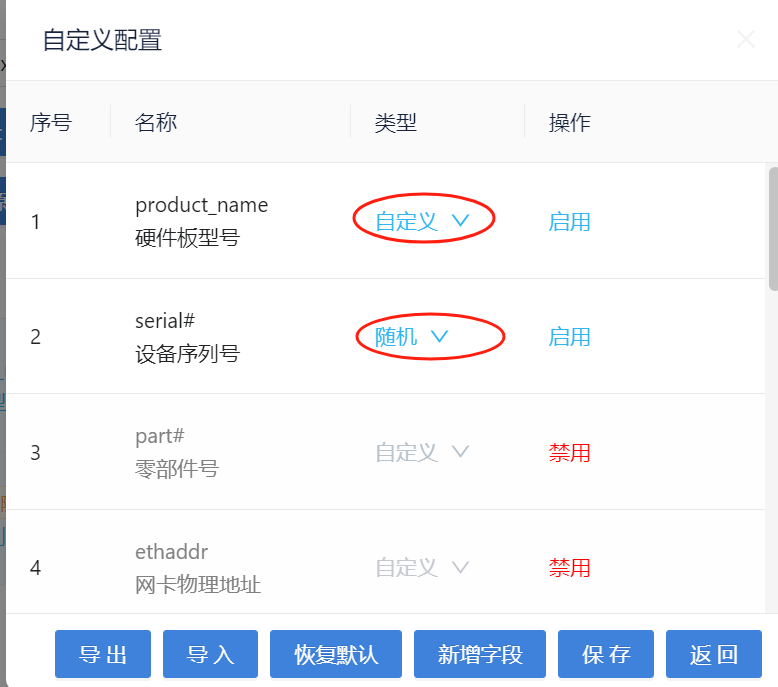
Click "Configure custom fields" to enter the settings
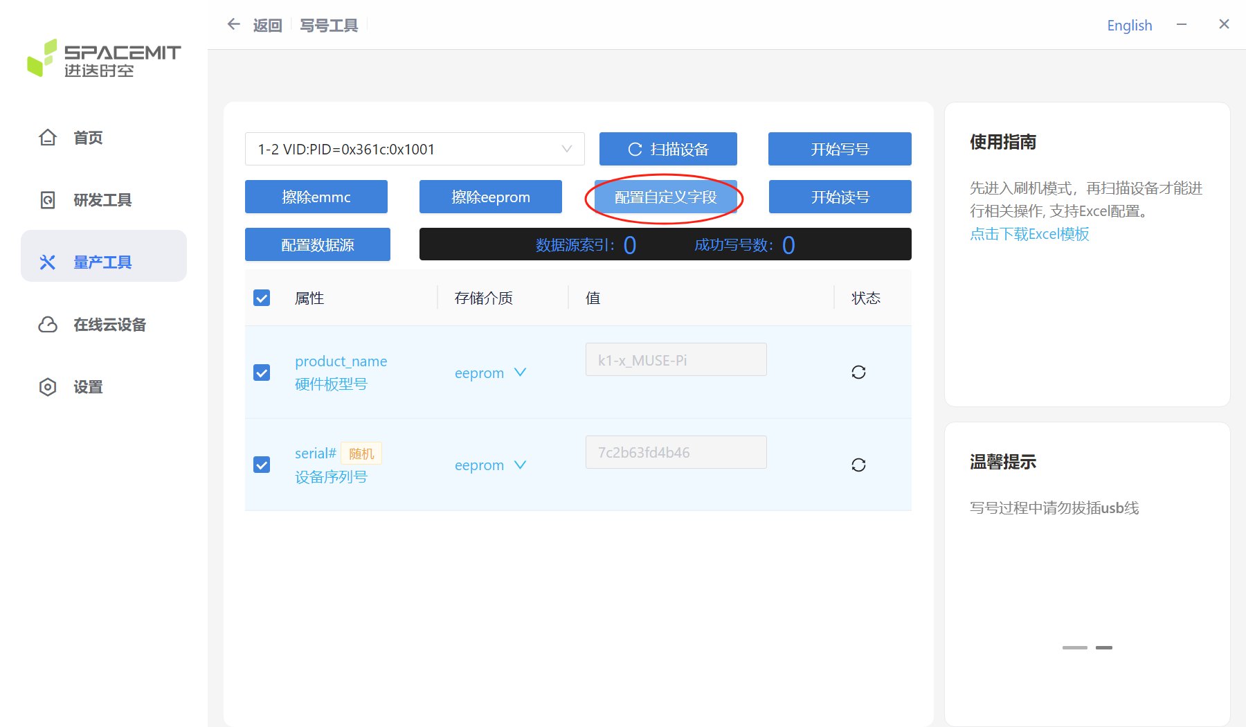
Enable the fields that need to be written, and disable the fields that do not need to be written
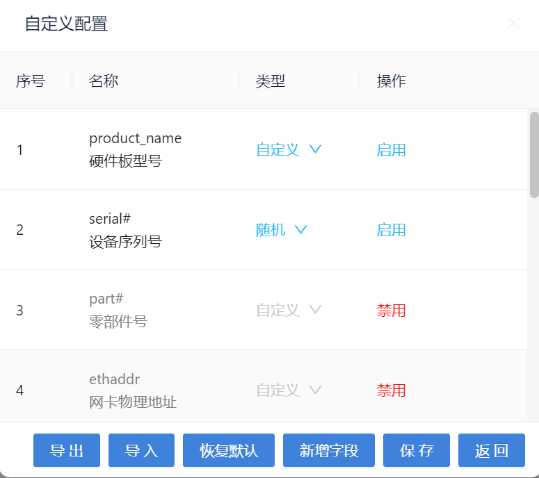
You can choose random or custom
After the settings are completed, click "Start writing number" and wait for the number to be written successfully.
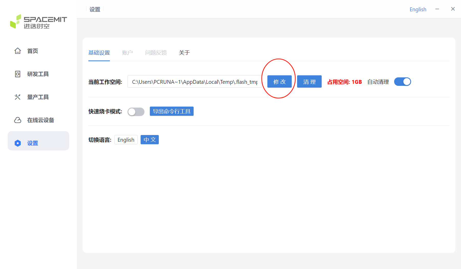
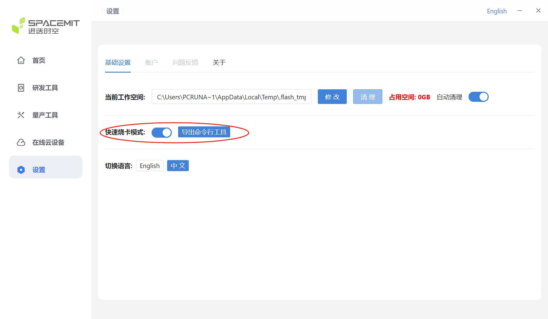
3.5 Settings
The figure below shows the settings interface.
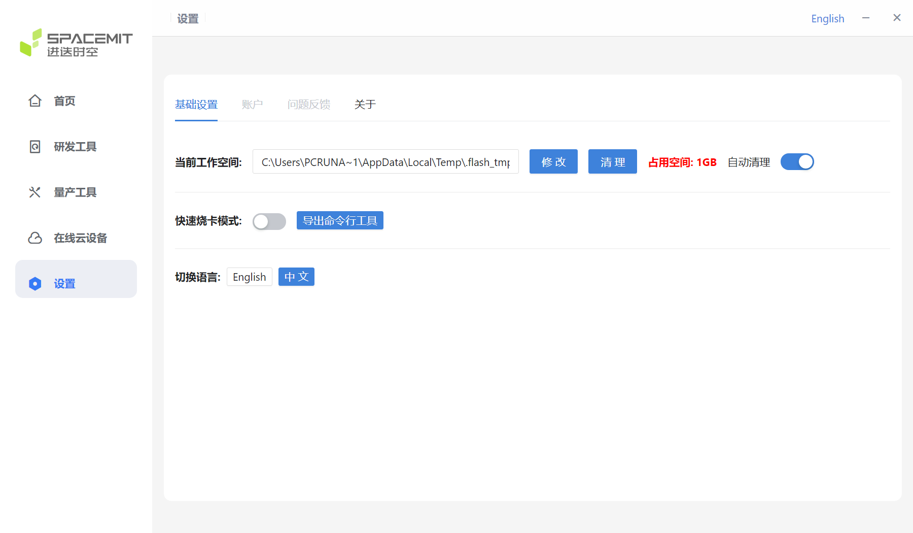
The red circle in the figure below shows the current workspace.
If you need to change the workspace, click Modify and reselect the workspace.
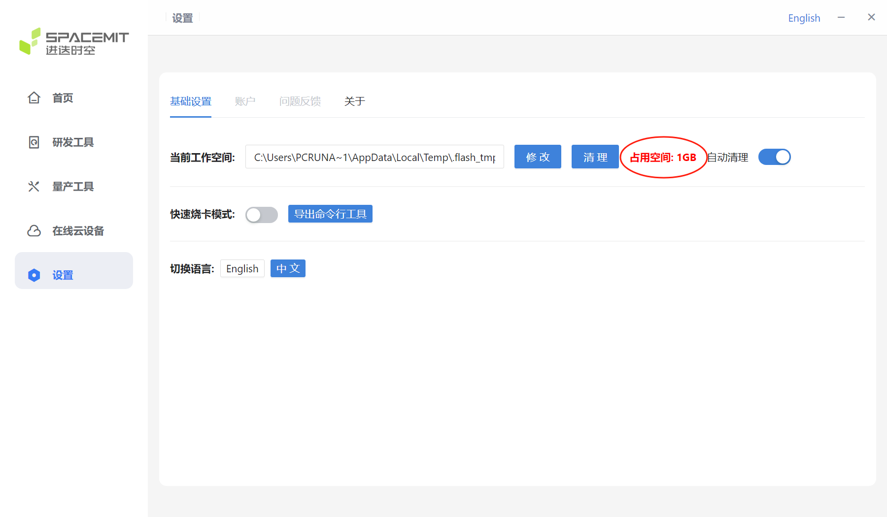
The red circle in the figure below shows the size of the current workspace.
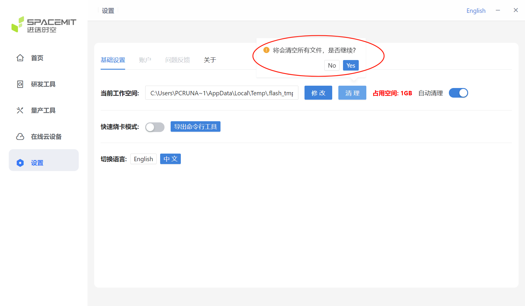
If you click the Clean button, the following window will pop up. Click Yes to clear all files in the current workspace.
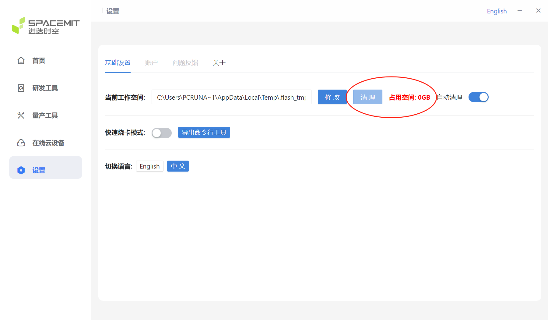
The cleanup is complete, and the current occupied space is shown as 0GB.
Automatic Cleanup

Fast card burning mode
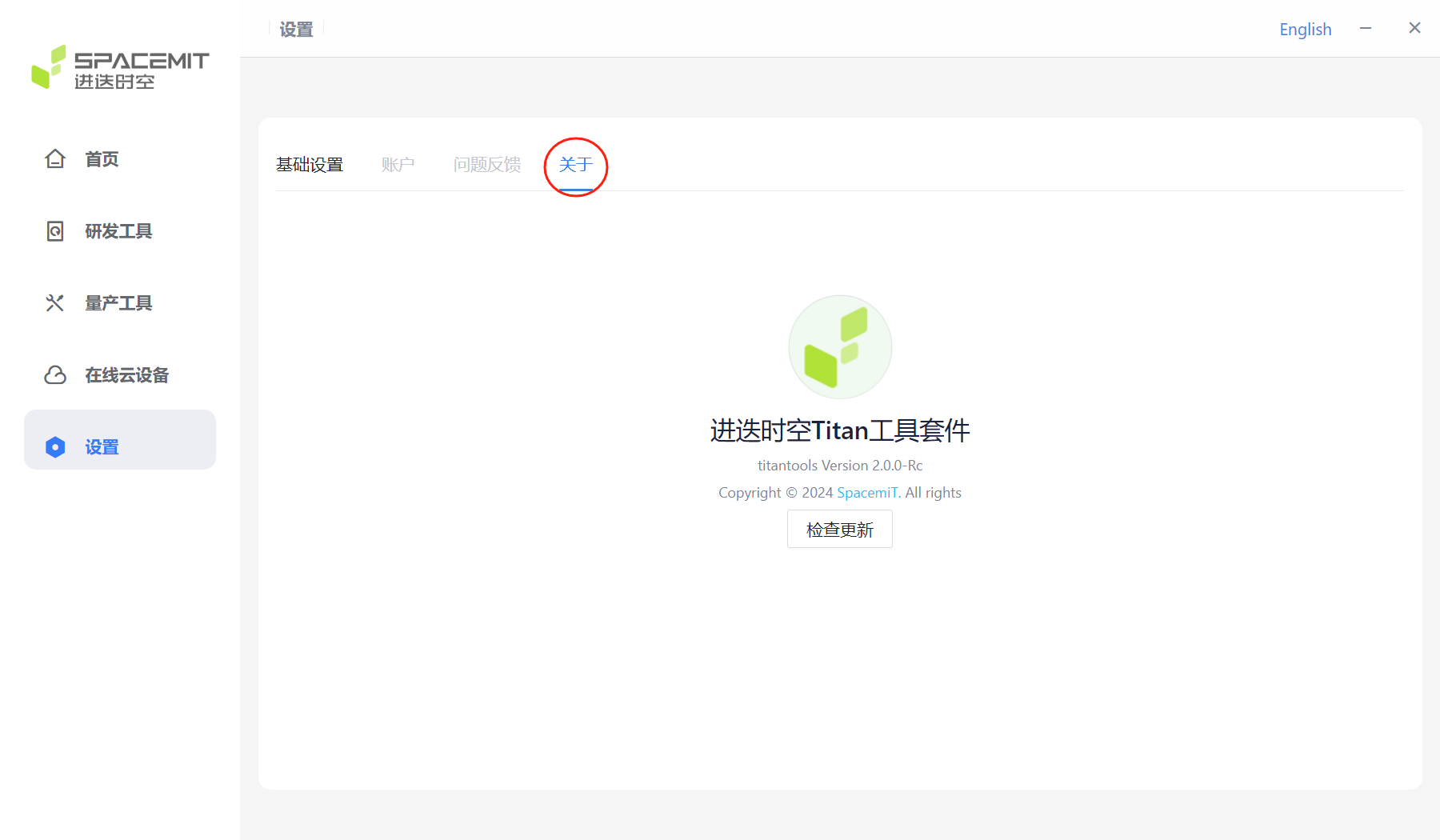
Click About to display the version information of the current flash tool kit.
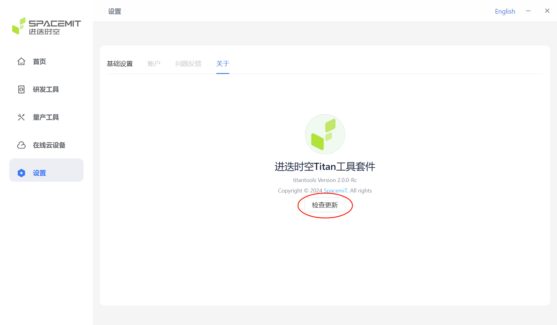
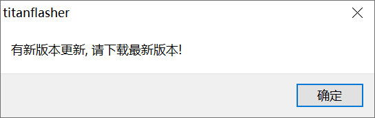
Click Check for updates to check if the current version is the latest one. If it is not the latest one, a prompt will pop up: There is a new version update, please download the latest version.
4 Flashing process
4.1 Enter flashing mode
When the device is not powered on and is in shutdown state:
Press and hold the "Download (FDL)" button and plug in the power cord. Release the "Download (FDL)" button and plug in the USB data cable to the flash USB connector to scan the device. The device has been plugged in and powered on. When it is in the power-on state:
Press and hold the FDL button; Short press the Reset button; Release the FDL button; Plug the USB data cable into the flash USB connector to scan the device
4.2 Flashing process
Open the flash tool, and if you are prompted to allow this app from an unknown publisher to make changes to your device?, select Yes.
Select Development Tools > Single Device Burning.
Click Scan Device until VID:PID appears. If there are multiple devices, select the device you want to flash. The device can only be scanned after entering the download mode.

Click Select Flash File, select the firmware, and then the tool prompts that the file is being unzipped..., wait patiently for the flashing to complete.
Or select the unzipped flash directory
Click Start Flashing to start the flashing process.
After the flashing is completed, you can enter the system by powering on again.