PWM (Pulse Width Modulation) control
1. PWM pins
Taking the SC-3568HA as an example, there are 3 GPIOs with PWM functions on the 40PIN pins of the board. Among them, PWM5 (PIN33) has already been occupied by the backlight of the MIPI1 screen.
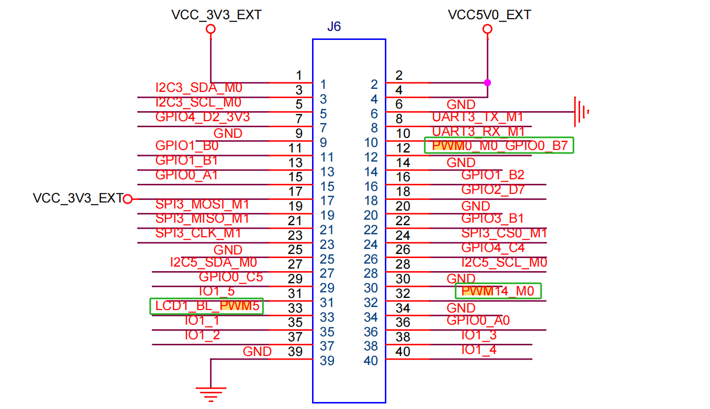
| Board | pin12 | pin32 | pin33 |
|---|---|---|---|
| SC-3568HA | pwm0 | pwm14 | pwm5 |
Note
By default, PWM0, PWM5, and PWM14 are all enabled.
2. Check the PWM device
Enter the following commands in the terminal to check whether PWM is enabled
ls -l /sys/class/pwm/As shown in the figure:

pwmchip1 and pwmchip2 are used for the backlight of the screen and are enabled by default in the system. When multiple PWM device tree overlays are enabled, the smaller the value of the PWM controller, the smaller the pwmchip assigned by the system.
For example, if I enable PWM0, PWM5, and PWM14 simultaneously, the following corresponding relationships will appear.

    pwm0->pwmchip0
    pwm5->pwmchip2
    pwm14->pwmchip3
3. PWM control mode
Next, take the control of PWM14 as an example
    #Export PWM14 to the user space
    echo 0 > /sys/class/pwm/pwmchip3/export

    #Set the PWM period with the unit of ns
    echo 1000000 > /sys/class/pwm/pwmchip3/pwm0/period

    #Set the duty cycle
    echo 500000 > /sys/class/pwm/pwmchip3/pwm0/duty_cycle

    #Set the PWM polarity
    echo "normal" > /sys/class/pwm/pwmchip3/pwm0/polarity

    #Enable PWM
    echo 1 > /sys/class/pwm/pwmchip3/pwm0/enable

    #Cancel the export of PWM14 to the user space
    echo 0 > /sys/class/pwm/pwmchip3/unexport
Tips
When setting the values of period and duty_cycle, it should be noted that under any circumstances, the value of period must be greater than or equal to the value of duty_cycle.