HOME
  • GM-3568JHF
  • M4-R1
  • M5-R1
  • SC-3568HA
  • M-K1HSE
  • CF-NRS1
  • CF-CRA2
  • 1684XB-32T
  • 1684X-416T
  • C-3568BQ
  • C-3588LQ
  • GC-3568JBAF
  • C-K1BA
Shop
  • English
  • 简体中文
HOME
  • GM-3568JHF
  • M4-R1
  • M5-R1
  • SC-3568HA
  • M-K1HSE
  • CF-NRS1
  • CF-CRA2
  • 1684XB-32T
  • 1684X-416T
  • C-3568BQ
  • C-3588LQ
  • GC-3568JBAF
  • C-K1BA
Shop
  • English
  • 简体中文
  • SC-3568HA

    • Introduction

      • SC-3568HA Overview
    • Quick Start Guide

      • OpenHarmony Overview
      • Image Flashing
      • Setting Up the Development Environment
      • Hello World Application and Deployment
    • Application Development

      • ArkUI

        • Chapter 1 Introduction to ArkTS Language
        • Chapter 2 Introduction to UI Components and Practical Applications (Part 1)
        • Chapter 3 Introduction to UI Components and Practical Applications (Part 2)
        • Chapter 4 Introduction to UI Components and Practical Applications (Part 3)
      • Expand

        • Chapter 1 Getting Started Guide
        • Chapter 2 Referencing and Using Third-Party Libraries
        • Chapter 3: Application Compilation and Deployment
        • Chapter 4: Command-Line Factory Reset
        • Chapter 5: System Debugging -- HDC (Huawei Device Connector) Debugging
        • Chapter 6 APP Stability Testing
        • Chapter 7 Application Testing
    • Device Development

      • Chapter 1 Environment Setup
      • Chapter 2 Download Source Code
      • Chapter 3 Compiling Source Code
    • Peripheral And Iinterface

      • Raspberry Pi interface
      • GPIO Interface
      • I2C Interface
      • SPI communication
      • PWM (Pulse Width Modulation) control
      • Serial port communication
      • TF Card
      • Display Screen
      • Touch
      • Audio
      • RTC
      • Ethernet
      • M.2
      • MINI-PCIE
      • Camera
      • WIFI&BT
      • Raspberry Pi expansion board
    • Frequently Asked Questions

      • Resource Downloads
  • M-K1HSE

    • Introduction

      • M-K1HSE Introduction
    • Quick Start

      • Development environment construction
      • Source code acquisition
      • Compilation Notes
      • Burning Guide
    • Peripherals and interfaces

      • 01 Audio
      • 02 RS485
      • 03 Display
    • System customization development

      • System transplant
      • System customization
      • Driver Development
      • System Debugging
      • OTA Update

02 RS485

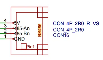
1 RS485 pin correspondence

White triangle corresponds to the first pin of the terminal - GND

RS485_1RS485_2

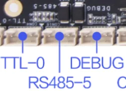
2 Check RS485 device

# 执行命令查看串口设备
ls /dev/ttyS*

As shown in the figure, ttyS5 is the device node corresponding to RS485

RS485_3

3 RS485 communication test

3.1 Connecting RS485

Connect the USB to RS485 devices A to A, B to B.

● 5V -- 5V ● A -- A ● B -- B ● GND -- GND

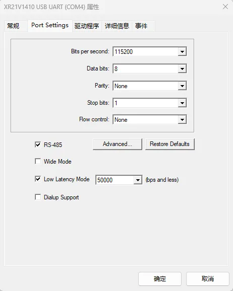
3.2 Set PC port configuration

Open the Device Manager → Port → Right-click the corresponding COM device and select Properties. Enter the device's properties interface, select Port Settings and check RS-485, as shown below

RS485_4

Notice

If the device corresponding to USB to RS485 is not found, please check whether the connection is correct and whether the driver is installed.

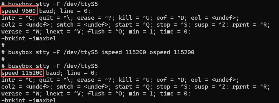
3.3 Query RS485 parameters and modify baud rate

# 在板卡的终端执行如下命令
busybox stty -F /dev/ttyS5

#设置通讯速率,其中ispeed为输入速率,ospeed为输出速率
busybox stty -F /dev/ttyS5 ispeed 115200 ospeed 115200

As shown in the figure:

RS485_5

Notice

The baud rate needs to be reset every time the device is turned on. The default baud rate is reset to 9600.

3.4 Communication with PC

3.4.1 RS485 Send Data

After configuring the serial port debugging assistant on the PC, use the following command on the board to test the serial port sending data:
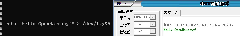
#在板卡上的终端执行如下指令

#使用echo命令向终端设备文件写入字符串"Hello OpenHarmony!"
echo "Hello OpenHarmony!" > /dev/ttyS5

As shown in the figure, the serial port debugging assistant on the PC will receive the content

RS485_6

3.4.2 RS485 receiving data

#在板卡上的终端执行如下指令
#使用microcom命令读取终端设备文件,-s参数可以设置波特率
microcom -s 115200 /dev/ttyS5
#microcom命令会等待

Use the serial port debugging assistant to send data, and the board's terminal will output the received data, as shown in the figure:

RS485_7
Edit this page on GitHub
Last Updated:
Contributors: zwhuang
Prev
01 Audio
Next
03 Display