Raspberry Pi expansion board
1. Raspberry Pi RS485/CAN expansion board
SC-3568HA does not support CAN communication. You can use this expansion board to expand one CAN channel through SPI communication.
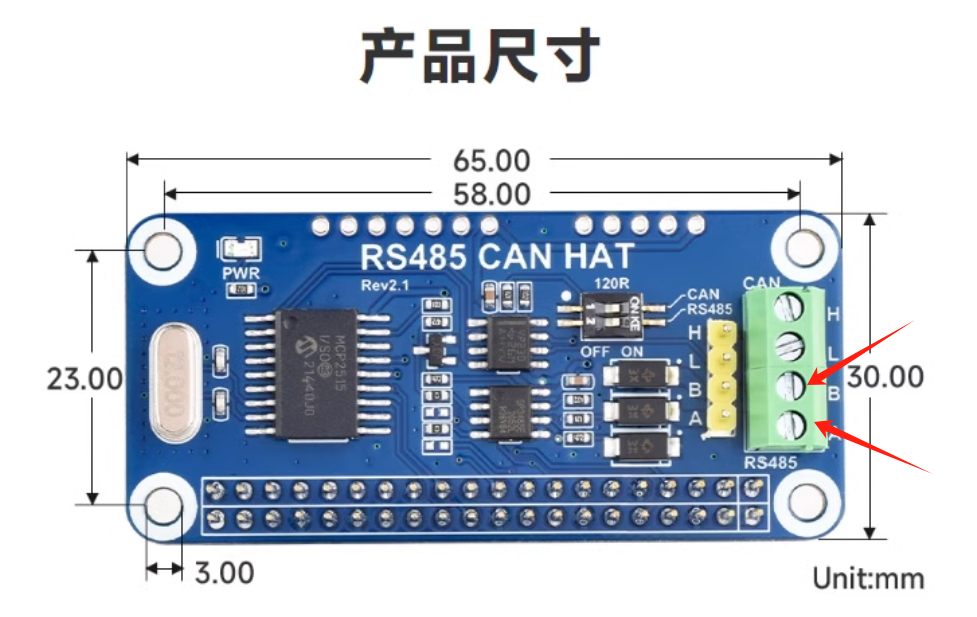
Expansion board physical picture:
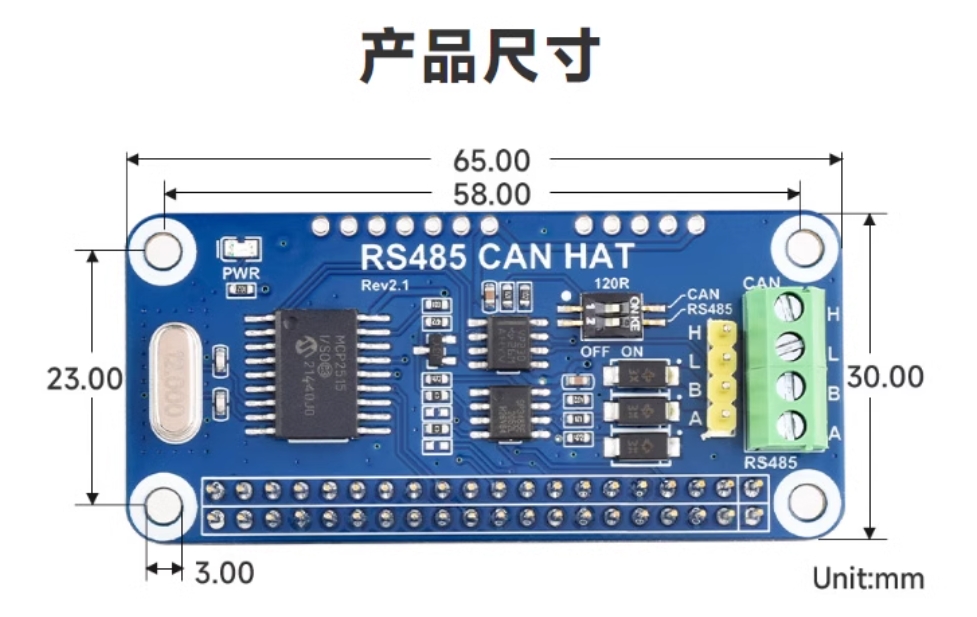
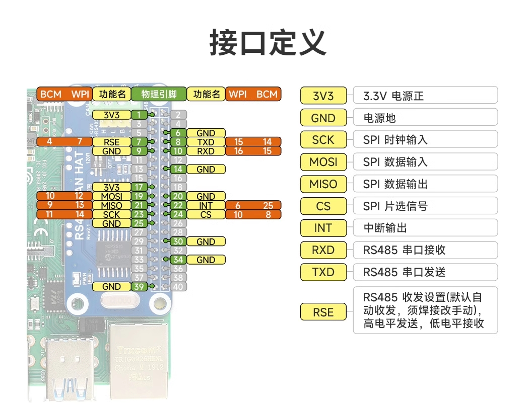
Expansion board pin comparison diagram:
2. CAN communication
2.1 DTS Configuration
This expansion board uses MCP2515 to implement CAN communication. The DTS configuration of MCP2515 is as follows:
Warning
The MCP2515 is not adapted in the firmware. If you need to use the CAN interface, you can configure it according to the following content.
- arch/arm64/boot/dts/rockchip/rk3568-toybrick-x0-linux.dts
    / {
        mcp251x_clk: mcp251x-clk {
                    compatible = "fixed-clock";
                    #clock-cells = <0>;
                    clock-frequency = <12000000>;       //根据MCP2515模块的硬件晶振设置 12MHz
            };
    };

    &spi3{
    	status = "okay";
        pinctrl-0 = <&spi3m1_cs0 &spi3m1_pins>;
        pinctrl-1 = <&spi3m1_cs0 &spi3m1_pins_hs>;
        max-freq = <5000000>;
        mcp2515: mcp2515 {
            compatible = "microchip,mcp2515";
            pinctrl-names = "default";
            pinctrl-0 = <&mcp2515_irq1_pins>;
            reg = <0>;
            clocks = <&mcp251x_clk>;
            spi-max-frequency = <2000000>;
            interrupt-parent = <&gpio3>;
            interrupts = <RK_PB1 IRQ_TYPE_EDGE_FALLING>;
            vdd-supply = <&vcc3v3_sys>;
            xceiver-supply = <&vcc3v3_sys>;
            status = "okay";
        };
    };

    &pinctrl {
        mcp2515 {
            mcp2515_irq1_pins: mcp2515-irq1-pins {
                            rockchip,pins = <3 RK_PB1 RK_FUNC_GPIO &pcfg_pull_none>;
                    };
            };
    };
2.2 CAN transceiver test
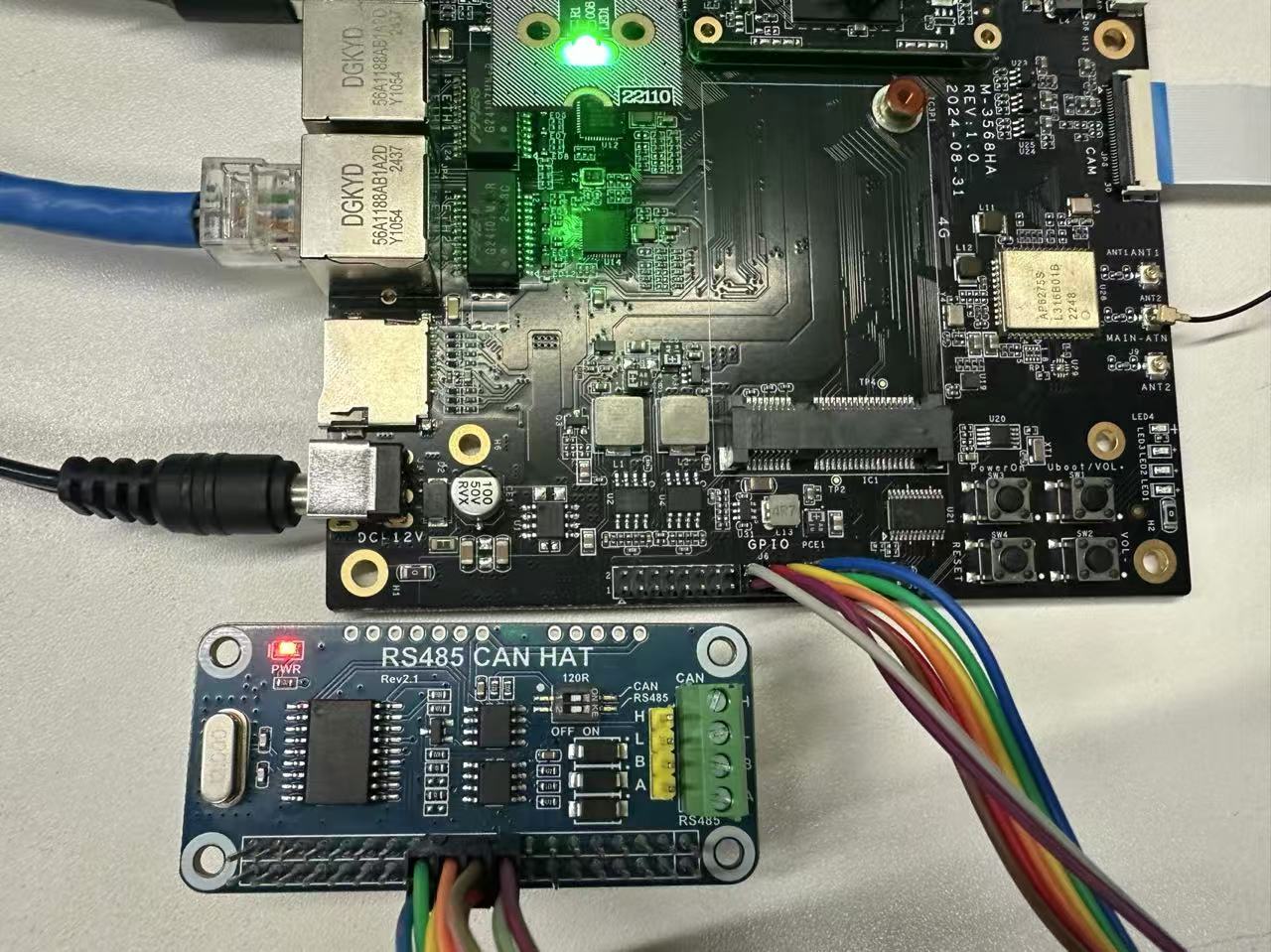
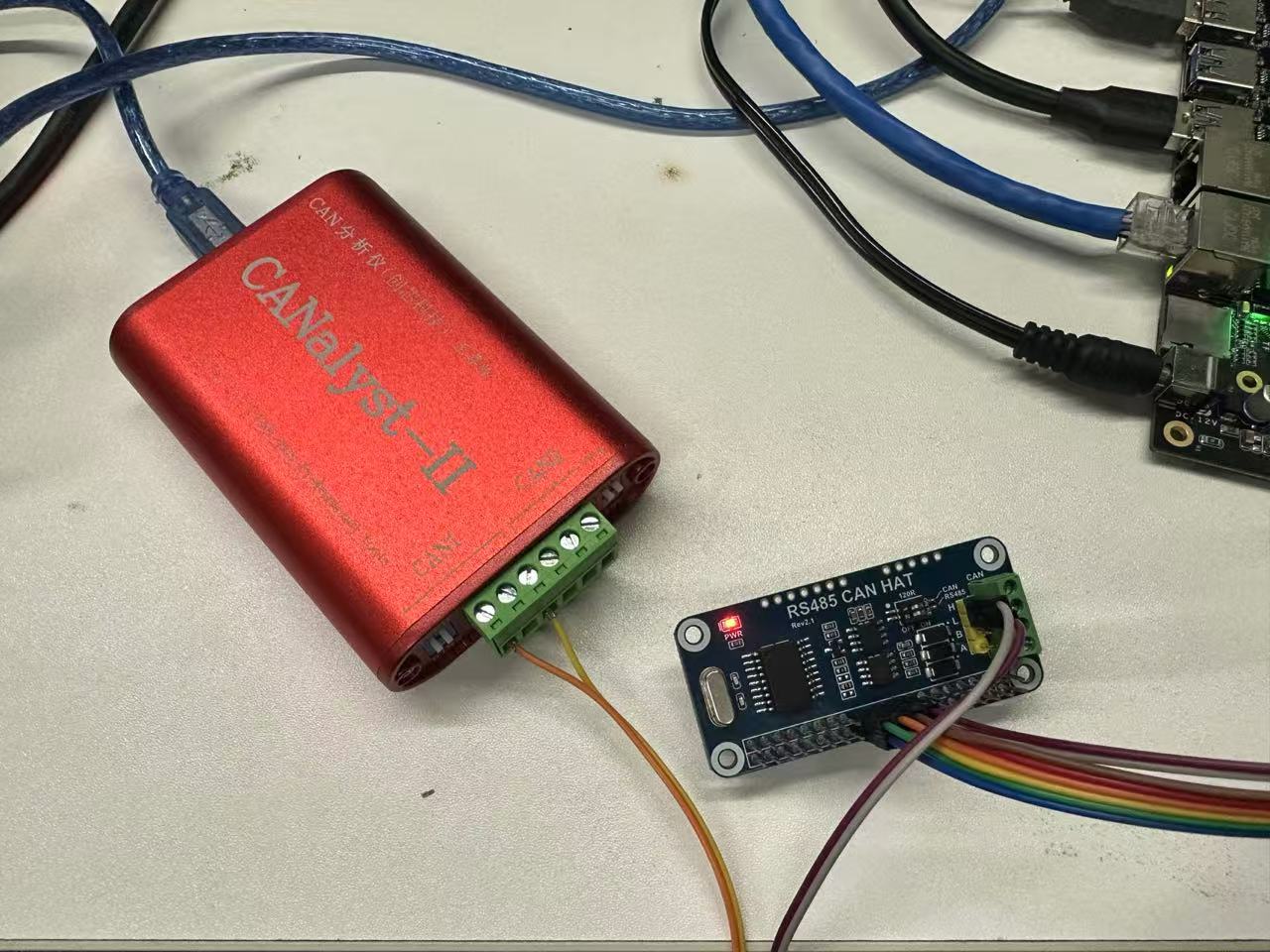
First, connect the expansion board to the SC-3568HA board 40PIN
The connection is as shown below:
2.2.1 Loopback test
The board comes with a CAN test tool. After connecting the expansion board, enter the command test
Warning
1.For the loopback test, there is no need to connect CAN_H and CAN_L.
2.The connection mode of the pins is one-to-one corresponding, that is, pin 1 corresponds to pin 1 of the expansion board.
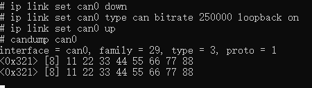
Set the baud rate and loopback mode:
    #Disable the CAN0 interface
    ip link set can0 down
    #Set the bit rate to 250000Hz and enable the loopback mode at the same time
    ip link set can0 type can bitrate 250000 loopback on
    #Enable the CAN0 interface
    ip link set can0 up
Open two terminal windows and test can0 self-transmission and reception:
    #Terminal 1
    candump can0

    #Terminal 2
    cansend can0 -i 0x321 0x11 0x22 0x33 0x44 0x55 0x66 0x77 0x88

    # Or use only one terminal
    candump can0 &
    cansend can0 -i 0x321 0x11 0x22 0x33 0x44 0x55 0x66 0x77 0x88
The test results are as follows:
- Terminal 1:
- Terminal 2:

2.2.2 Communication test with CAN analyzer
Connect the expansion board and the analyzer.
| Expansion Board | CAN Analyzer |
|---|---|
| CAN_H | CAN_H |
| CAN_L | CAN_L |
Set the baud rate and test
#Disable the CAN0 interface
sudo ip link set can0 down
#Set the bit rate to 250000Hz
sudo ip link set can0 type can bitrate 250000
#Enable the CAN0 interface
sudo ip link set can0 up
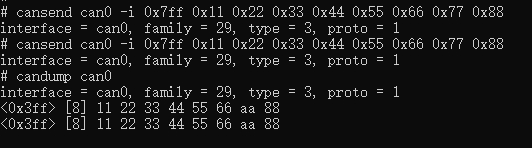
#Send (Standard frame, data frame, ID: 7ff, data: 11223344556677)
cansend can0 -i 0x7ff 0x11 0x22 0x33 0x44 0x55 0x66 0x77 0x88
#Receive
candump can0- Terminal test results:
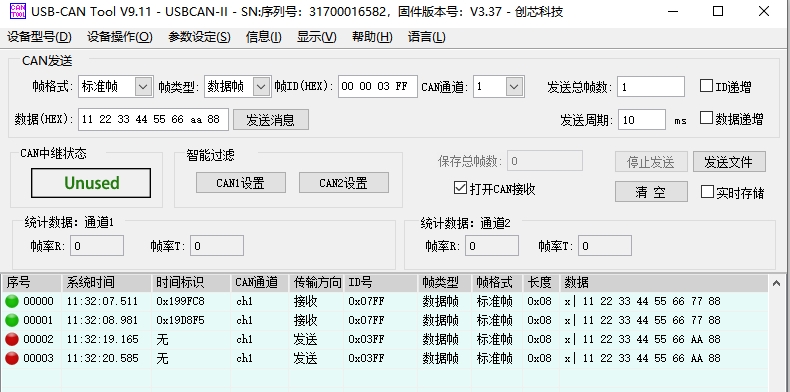
- CAN analyzer test results:
3. RS485
The expansion board 485 supports automatic switching of the receiving and sending states without program control. You only need to connect the 8th and 10th pins of the expansion board to the 8th and 10th pins of the 40PIN of SC-3568HA, and then connect the 485 device to the A and B of the expansion board for receiving and sending.