SPI communication
1. SPI functional features
SPI (serial peripheral interface). The following are some features supported by the Linux 4.4 SPI driver:
- The Motorola SPI protocol is adopted by default.
- Supports 8-bit and 16-bit.
- The software-programmable clock frequency and transmission rate can reach up to 50MHz.
- Supports the configuration of 4 SPI transmission modes.
- Each SPI controller supports one to two chip selects.
- The framework supports both slave and master modes.
2. SPI pins
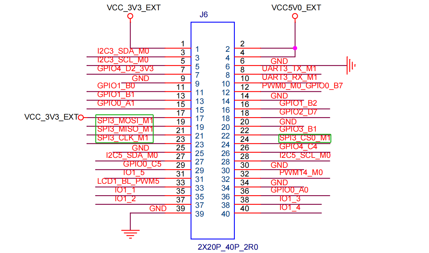
| SPI | PIN | Functions |
|---|---|---|
| MOSI | 19 | Master Output/Slave Input (MOSI) |
| MISO | 21 | Master Input/Slave Output (MISO) |
| CLOCK | 23 | Clock Signal Line |
| CS0 | 24 | Chip Select Signal Line 0 |
Warning
spidev3.0 controls CS0
3. Device Tree Source (DTS) configuration
Enable SPI in arch/arm64/boot/dts/rockchip/rk3568-toybrick-x0-linux.dts.
    &spi3 {
        status = "okay";
        pinctrl-0 = <&spi3m1_cs0  &spi3m1_pins>;
        pinctrl-1 = <&spi3m1_cs0  &spi3m1_pins_hs>;
        spidev:spidev@0 {
                compatible = "rockchip,spidev";
                reg = <0>;
                spi-max-frequency = <10000000>;
                status = "okay";
        };
    };
4. Check the SPI device
Enter the following commands in the board's terminal to check whether the SPI device is created

5. SPI loopback test
Short-circuit the MOSI and MISO (it is recommended to use a jumper cap for short-circuiting to ensure data stability).

Use the loopback test program available online to test whether the SPI is working properly.
When short-circuiting, the data is correct.

When there is no short-circuiting, the data appears as garbled characters.
