01 UART read and write case
Case Introduction
This case aims to introduce how to test the UART serial communication function on the development board.
The serial ports supported by the development board and their corresponding device nodes are shown in the following table.
| Serial Port | Device Node |
|---|---|
| RS232 UART0 | ttyS0 |
| TTL UART0 | ttyS4 |
| RS485 UART7 | ttyS7 |
| RS485 UART8 | ttyS8 |
The following will take TTL UART0 as an example to explain the test process in detail, including hardware connection, software configuration, and specific steps to implement serial port read and write functions.
Pre-test preparation
Before you begin testing, follow these steps to prepare:
Hardware Hookup
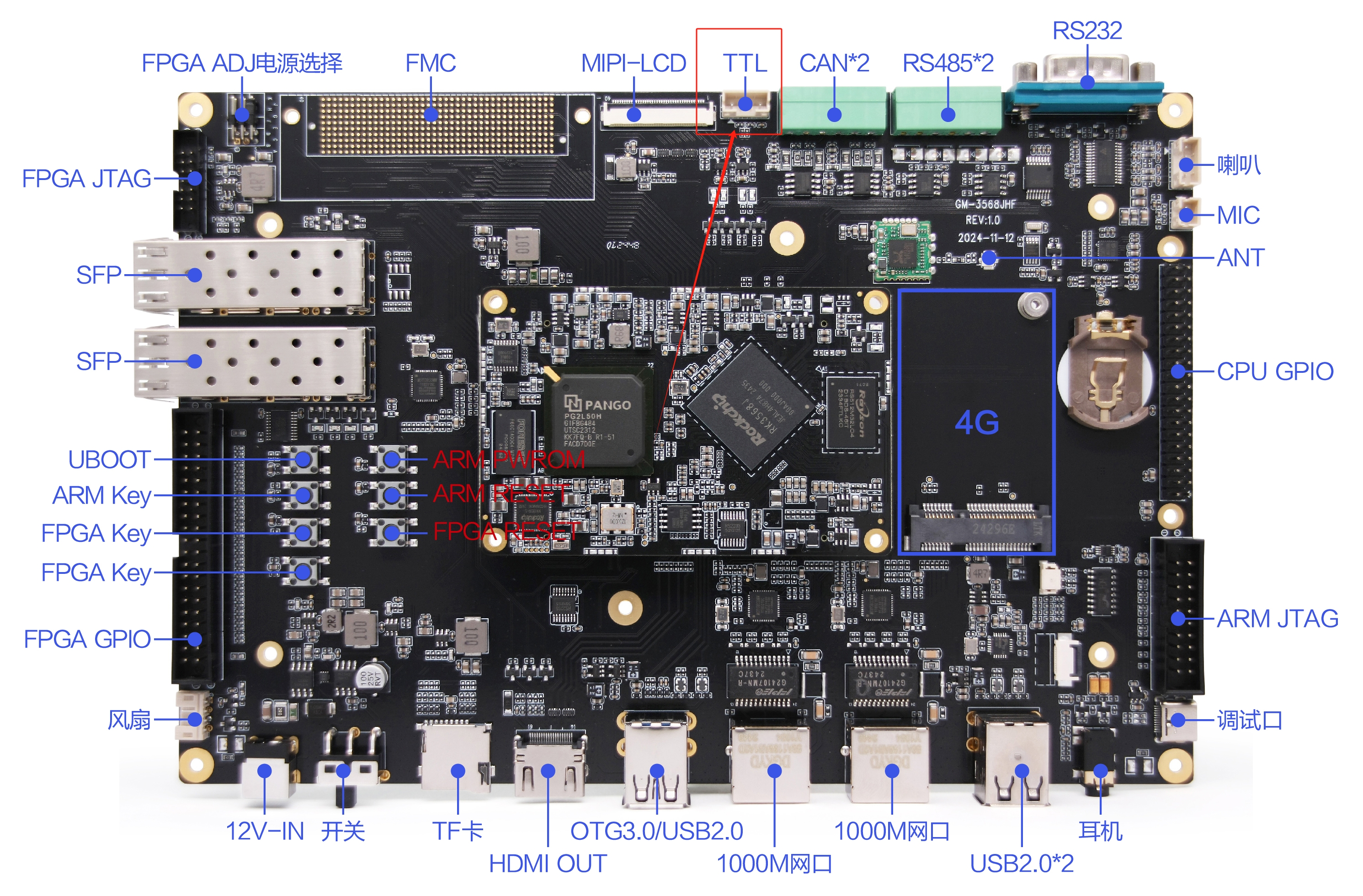
Use a USB to TTL serial port module to connect the PC to the TTL UART4 interface of the development board. The specific location of the TTL UART4 interface is shown in the figure. Please ensure that the connection is correct and stable.
Software Preparation
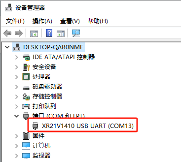
Open the device manager and confirm that the device has been correctly identified. After the first connection, you may need to restart the PC to identify the correct device name "XR21V1410 USB UART", as shown in the figure.
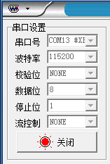
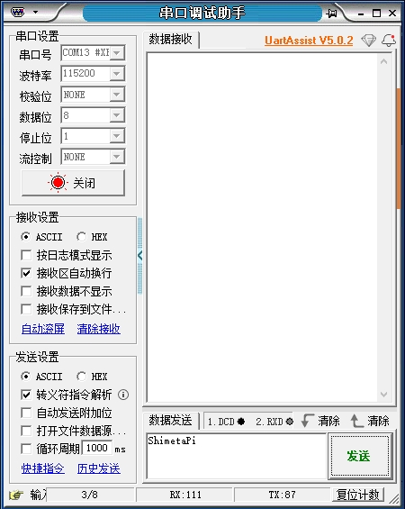
Open the serial port debugging tool on the PC (see "Quick Development/Debugging Tool Installation" for window debugging tool installation) and select the corresponding serial port number, for example, COM13 in this case. Set the baud rate to 115200, the data bit to 8, and no parity bit. The configuration is as shown in the figure below. Click "Open" to create the connection.
Operation process
TTL UART4 serial port test
Copy the executable program smdt_uart_rw in the bin directory of this case (05-Development Materials\Software Development Materials\linux_demo\smdt_uart_rw\bin) to the development board file system (the source code can be viewed in the src path). Open the terminal and execute the following command to switch to the directory where the smdt_uart_rw executable program is located.
cd ‘the file's directory’After switching, you can run the command "ls" to check whether the smdt_uart_rw executable program is in the current directory.
lsIf the executable file smdt_uert_rw exists in the current directory, continue to perform the following operations: Enter the following command to modify the file permissions.
chmod 777 smdt_uart_rwAfter modifying the permissions, you can enter the following command to check whether the modification is successful.
ls -ld smdt_uart_rwThe execution result is: -rwxrwxrwx 1 root root 19016 Mar 3 09:55 smdt_uart_rw.
-rwxrwxrwx means the permissions have been modified successfully, the file can be executed, and you can continue with the following operations.
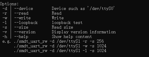
Continue to enter instructions and view program parameter information.
./smdt_uart_rw -hThe result after execution is as follows:
Development board receiving
Enter the following command and wait for receiving data from the PC
./smdt_uart_rw -d /dev/ttyS4 -r -s 9Use the serial port debugging tool on the PC to send "ShimetaPi".
The development board debugging serial port terminal will print the received data.

Development board sent
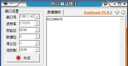
Execute the following command, the development board sends data to the PC through the UART4 serial port, and the data sent is "012345670".
./smdt_uart_rw -d /dev/ttyS4 -w -s 9
The serial port debugging tool will receive the following data.