10 Ethernet Test Cases
1 Case Introduction
This case aims to introduce how to achieve Ethernet communication between the development board and the PC.
2. Preparation before the test
Connect the network ports of the PC and development board to the same switch via network cables.
Enter the following command in the development board terminal to query the IP address of the network interface. The execution result is shown in the figure below.
ifconfig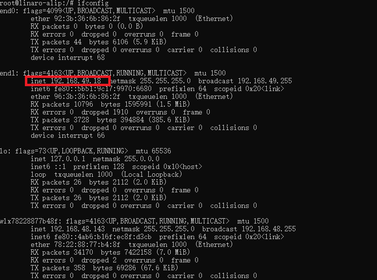
Enter the following command on the PC terminal to query the IP address of the PC network interface. The execution result is shown in the figure below.
ipconfig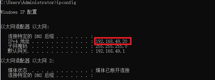
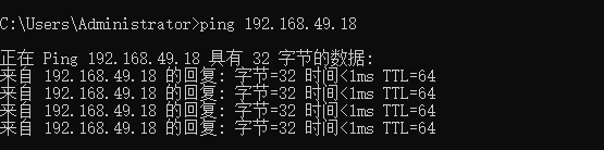
Execute the ping command on the development board terminal and PC terminal respectively.
# On the development board terminal
ping <PC IP address>

# On the PC terminal
ping <Development board IP address>

#e.g:ping 192.168.49.20
The execution result is shown in the figure below, indicating that the network connection is unobstructed.
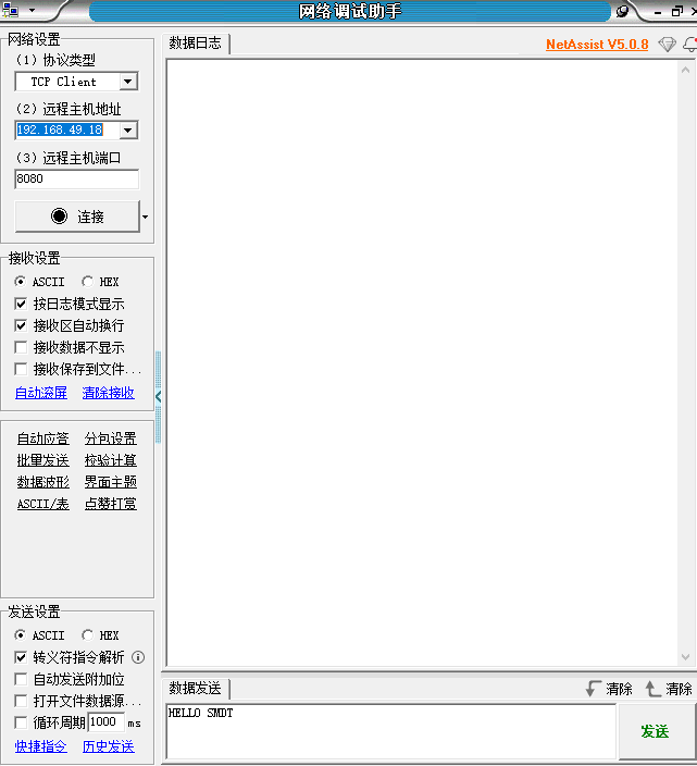
Open the software NetAssit in directory 04-Software Information\Tools\Windows . Select TCP Client as the protocol type , enter the queried IP address as the remote host address, and select 8080 as the remote host port . The configuration interface is shown in the figure below.
3 Operation process
Open the terminal and copy the executable program smdt_eth_demo in the bin directory of this case (05-Development Materials\Software Development Materials\linux_demo\smdt_eth_demo\bin) to the development board file system (the source code can be viewed in the src path).
Execute the following command in the terminal and switch to the directory where the smdt_eth_demo executable program is located.
#切换到 smdt_eth_demo 可执行程序所在目录
cd ‘the file's directory’

#查看 smdt_eth_demo 是否在该目录下
ls
If the executable file smdt_eth_demo is in the current directory, modify the permissions of the executable file.
#添加可执行权限
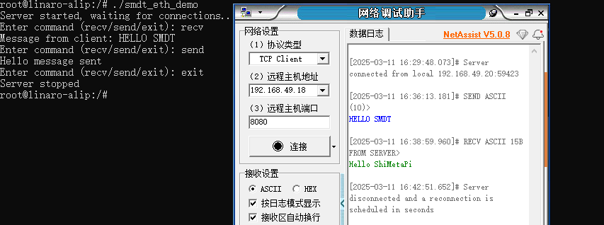
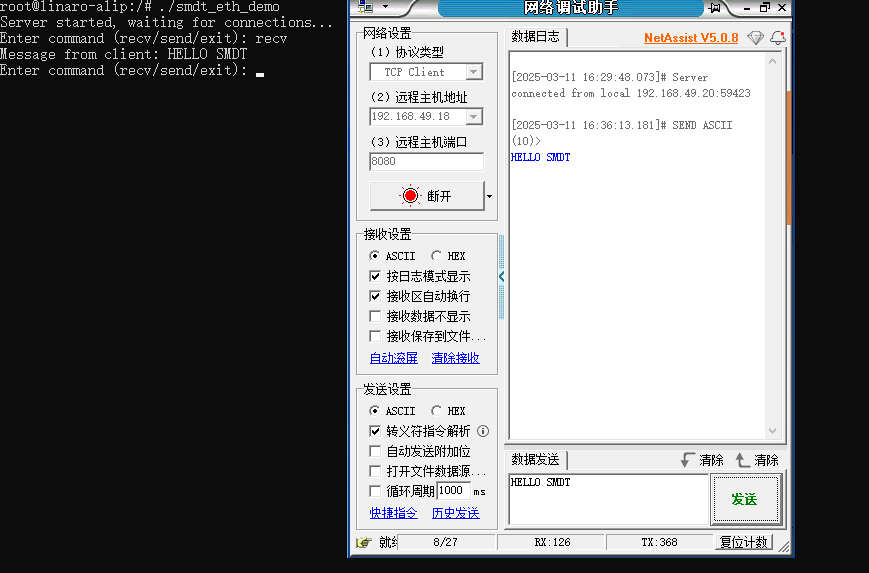
chmod +x smdt_eth_demoExecute the following command, the development board waits for the PC to connect. Click Connect in the NetAssit software . The execution result is shown in the figure below. The two devices have successfully established an Ethernet connection and are waiting for the user to enter a command.
./smdt_eth_demo
Three commands can be entered at the input end: recv : receive data from the PC; send : send data to the PC; exit : disconnect the Ethernet connection between devices.
Enter recv in the command line , press Enter, and wait for the PC to send data. Enter "Hello SMDT" in the debugging assistant and click Send. The development board can receive the corresponding string. As shown in the figure below.
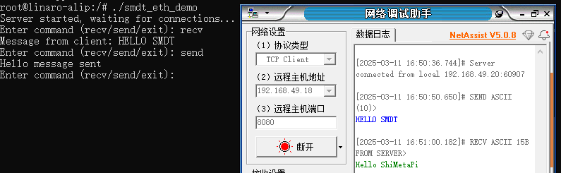
Enter send in the command line and press Enter. The development board sends the data "Hello ShiMetaPi" to the PC. In the debugging assistant window, you can see the string sent from the development board to the PC, as shown in the figure below.
Type exit in the command line to disconnect the Ethernet connection between the two devices.