12 FPGA IIC read and write examples
1 Case Introduction
Case function description: This case mainly demonstrates how to implement read and write operations on FPGA registers on the ARM side through the IIC communication protocol. The case is based on the standard IIC tools of the Linux system (such as i2cset, i2cget, i2cdetect, etc.), customizes the test program, provides a complete IIC communication test process, and verifies the correctness of IIC communication.
2. Standard IIC tools to read and write FPGA
In IIC communication, FPGA acts as a slave, and the slave address can be viewed through the following command. As shown in the figure, its device address is 0x66.
i2cdetect -r -y -a 0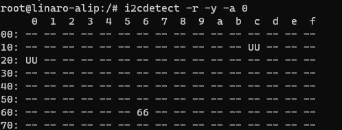
Currently, three register addresses are defined in the code: 0x00, 0x01, and 0x02. 0x02 is a read-only register. For the 0x00 register, you can test whether the read and write data are correct. For example, if you write 1 and read 1, the communication is normal.
Execute the following command to write the value 0X40 into the 0X00 register .
i2cset -r -y -a 0 0x66 0x00 0x40
Execute the following command to read the value of register 0x00. You can see that 0x40 is read, which is consistent with the written value.
i2cget -f -y -a 0 0x66 0x00
You can also execute the following command to view the values of all registers of the device.
i2cdump -f -y -a 0 0x66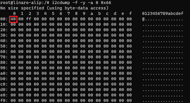
Among them, the 0x01 register can control the state of the LED light on the baseboard. You can write a value to the 0X01 register to control the state of the LED light.
#点亮
i2cset -f -y -a 0 0x66 0x01 0x01
#熄灭
i2cset -f -y -a 0 0x66 0x01 0x01
3 Case operation process
This case is based on the standard IIC tool of the Linux system, and optimizes the instruction design to make it more intuitive and user-friendly. Users can modify the source program according to their needs.
Open the terminal and copy the executable program smdt_fpga_i2c in the bin directory of this case (05-Development Materials\Software Development Materials\linux_demo\smdt_fpga_i2c_demo\bin) to the development board file system (the source code can be viewed in the src path).
#Modify the display level of Linux kernel logs, setting the kernel's logging level to show only emergency or higher-level messages.
echo 1 4 1 7 > /proc/sys/kernel/printk
Execute the following command in the terminal and switch to the directory where the smdt_fpga_i2c executable program is located
#切换到 smdt_fpga_i2c 可执行程序所在目录
cd ‘the file's directory’

#查看 smdt_fpga_i2c 是否在该目录下
ls
If the executable file smdt_fpga_i2c is in the current directory, modify the permissions of the executable file
#修改文件权限
chmod 777 smdt_fpga_i2c

#查询是否修改成功
ls -ld smdt_fpga_i2c
After confirming that the file modification permission is successful, execute ./smdt_fpga_i2c -h to view the help information of the program.
./smdt_fpga_i2c -hThe execution result is as follows:
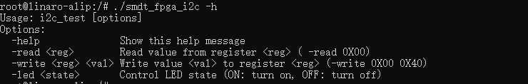
Execute the following commands to read and write device register 0X00.
#写操作
 ./smdt_fpga_i2c -write 0x00 0x11
 #读操作
  ./smdt_fpga_i2c -read 0x00
Execute the following command to write to the device register 0X01 to control the LED on the baseboard.
#点亮
  ./smdt_fpga_i2c -led ON
  #熄灭
  ./smdt_fpga_i2c -led OFF