08 FPGA DMA read and write case
1 Case Introduction
Case function description: The ARM side uses the PCIe bus to perform read and write operations on the FPGA's DRAM. After the application triggers DMA data transfer through the ioctl function, it will wait for the input event issued by the driver as a response. When the application receives this event, it indicates that the DMA data transfer has ended.
2 Test program execution flow
ARM
Write the data to the continuous memory space (located in DDR) requested by the dma_memcpy driver. Configure DMA, such as source address, destination address, data size to be transferred, etc.
Write operation: Start DMA through the ioctl function and move data to the FPGA DRAM through the PCIe bus. After the program receives the input event reported by the driver, it will obtain the time taken by DMA to move data through the ioctl function and calculate the DMA write rate.
Read operation: Start DMA through the ioctl function, and move the data in the FPGA DRAM to the continuous memory space (located in DDR) requested by the dma_memcpy driver through the PCIe bus; after the program receives the input event reported by the driver, it reads the data from the kernel space to the user space, and then verifies the data. At the same time, the ioctl function is used to obtain the DMA data transfer time and calculate the DMA read rate.
FPGA end
Implement PCIe Endpoint function;
Process the PCIe BAR0 space read and write transactions initiated by the PCIe RC end;
Cache PCIe BAR0 read and write data into FPGA DRAM.
3 Operation process
Open the terminal and copy the executable program smdt_dma_memcpy_demo in the bin directory of this case (05-Development Materials\Software Development Materials\linux_demo\smdt_fpga_dma_memcpy_demo\bin) to the development board file system (the source code can be viewed in the src path).
#修改 Linux 内核日志的显示级别,内核的日志级别被设置为只显示紧急或更高级别的消息
echo 1 4 1 7 > /proc/sys/kernel/printk
Execute the following command in the terminal and switch to the directory where the smdt_dma_memcpy_demo executable program is located
#切换到 smdt_dma_memcpy_demo 可执行程序所在目录
cd ‘the file's directory’

#查看 smdt_dma_memcpy_demo 是否在该目录下
ls
If the executable file smdt_dma_memcpy_demo is in the current directory, modify the permissions of the executable file
#修改文件权限
chmod 777 smdt_dma_memcpy_demo
#查询是否修改成功
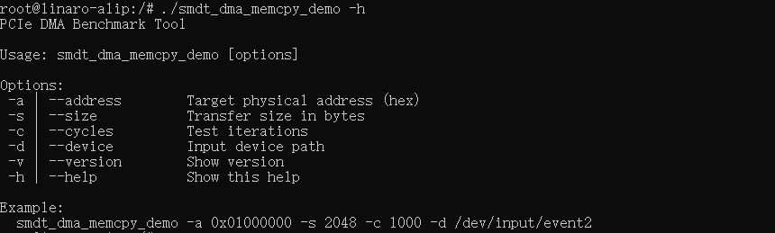
ls -ld smdt_dma_memcpy_demoAfter confirming that the file modification permission is successful, execute ./smdt_dma_memcpy_demo -h to view the help information of the program.
#查看帮助信息
./smdt_dma_memcpy_demo  -h
#-a:Set the PCIe address.
#-s:Set the size of the transmitted data (unit: Byte).
#-c:Set the number of read/write cycles.
#-d:Set the input device.
#-v:Display version information.
#-h:Display help content.
The execution result is as follows:
Execute the following command to view the PCIe BAR space address. As shown in the figure below, the PCIe BAR space is mapped to the address 0xf0200000, with a size of 64KByte, and view the PCIe device connection status.
lspci -s 0002:21:00.0 -vv
Run the following command to enable the PCIe device.
echo 1 > /sys/class/pci_bus/0002\:21/device/0002\:21\:00.0/enableAfter the application sends a command through the ioctl function to start DMA data transmission, it waits for the driver to report the input event; when the application layer receives the input event, it means that the DMA data transmission is completed. Execute the following command to view the input event interface. As shown in the figure, the input event interface is /dev/input/event0.
evetest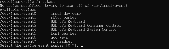
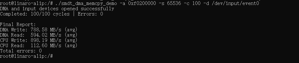
Execute the following instructions to write randomly generated data into the FPGA's DRAM, and then read data from the FPGA's DRAM. After the test is completed, the event notification is received through /dev/input/event0, and the test results are output, including statistical information such as average read and write time, average transfer rate, and number of read and write errors. The execution results are shown in the figure below.
./dma_memcpy_demo -a 0xf0200000 -s 65536 -c 100 -d /dev/input/event6
#The event0 here should be changed according to the results queried by evetest.