Display and touch
MIPI DSI interface
Hardware Hookup
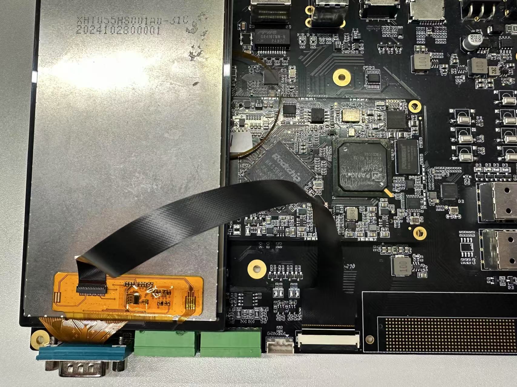 Connect the MIPI display to the MIPI interface of the development board through the FPC cable as shown in the figure. Make sure the power supply and signal cables of the display are connected correctly.
MIPI screen display test
After the development board is powered on, you can see the following interface on the MIPI screen.

Backlight test
Run the following command to change the screen brightness by modifying the brightness level.
root@linaro-alip:/# echo 1 > /sys/class/backlight/backlight/brightness
root@linaro-alip:/# echo 255 > /sys/class/backlight/backlight/brightness
HDMI port
The HDMI interface of the development board is a standard HDMI, which is hot-swappable and has adaptive resolution
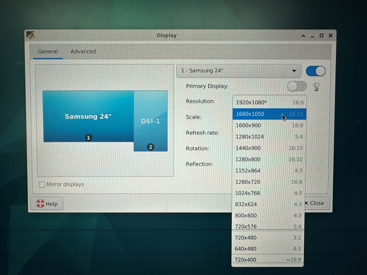
Desktop switch resolution
- Open System Settings and find Display
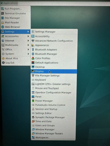
- Click Resolution to switch between different resolutions
Switch different resolutions via command line
- Use the xrandr -q parameter to view the resolution currently supported by your screen.
root@linaro-alip:/# xrandr -q
Screen 0: minimum 320 x 200, current 2640 x 1280, maximum 16384 x 16384
HDMI-1 connected 1920x1080+0+0 (normal left inverted right x axis y axis) 527mm x 296mm
   1920x1080     60.00*+  74.97    50.00    59.94
   1680x1050     59.88
   1600x900      60.00
   1280x1024     75.02    60.02
   1440x900      59.90
   1280x800      59.91
   1152x864      75.00
   1280x720      60.00    50.00    59.94
   1024x768      75.03    70.07    60.00
   832x624       74.55
   800x600       72.19    75.00    60.32    56.25
   720x576       50.00
   720x480       60.00    59.94
   640x480       75.00    72.81    66.67    60.00    59.94
   720x400       70.08
Use the xrandr -s 0 command to restore the screen to its original resolution.
xrandr -s specifies the screen resolution
For example:
xrandr -s 1280x800touchscreen
There is a set of I2C TP interfaces on the development board, and the default touch IC driver is gt911
Hardware Hookup
The connections are shown in the figure below:

Swipe or tap the screen to test whether it works properly