CAN
CAN bus protocol (Controller Area Network), controller area network bus, is a serial communication protocol bus developed by BOSCH of Germany. It can use twisted pair cables to transmit signals and is one of the most widely used field buses in the world.
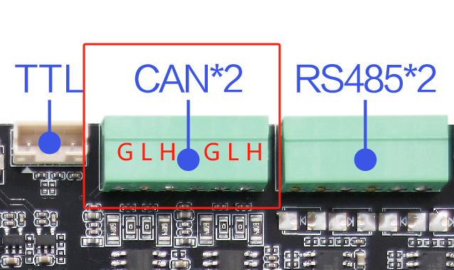
CAN Hardware Connection
The CAN wiring of the development board and external devices is as follows:
| Development Boards | External devices |
|---|---|
| CAN_L | CAN_L |
| CAN_H | CAN_H |
CAN communication test
This test uses a CAN analyzer to test, just connect the H and L ends of the two devices

Check the interface
Check whether the can0 and can1 interfaces of the development board are generated
root@linaro-alip:/# ifconfig -a
can0: flags=128<NOARP>  mtu 16
        unspec 00-00-00-00-00-00-00-00-00-00-00-00-00-00-00-00  txqueuelen 10  (UNSPEC)
        RX packets 0  bytes 0 (0.0 B)
        RX errors 0  dropped 0  overruns 0  frame 0
        TX packets 0  bytes 0 (0.0 B)
        TX errors 0  dropped 0 overruns 0  carrier 0  collisions 0
        device interrupt 54

can1: flags=128<NOARP>  mtu 16
        unspec 00-00-00-00-00-00-00-00-00-00-00-00-00-00-00-00  txqueuelen 10  (UNSPEC)
        RX packets 0  bytes 0 (0.0 B)
        RX errors 0  dropped 0  overruns 0  frame 0
        TX packets 0  bytes 0 (0.0 B)
        TX errors 0  dropped 0 overruns 0  carrier 0  collisions 0
        device interrupt 55
···
Parameter settings
The development board sets the baud rate and performs a test (this time CAN0 is used as the test sample)
#将CAN0接口关闭
sudo ip link set can0 down
#设置比特率为 250000
sudo ip link set can0 type can bitrate 250000
#将CAN0接口启用
sudo ip link set can0 up
#发送(标准帧,数据帧,ID:7ff,date:11223344556677)
cansend can0 -i 0x7ff 0x11 0x22 0x33 0x44 0x55 0x66 0x77 0x88
#接收
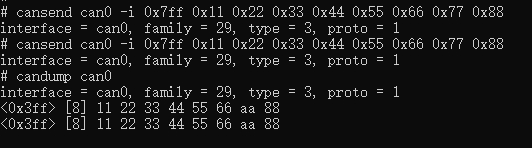
candump can0Test Results
- Development board test results:
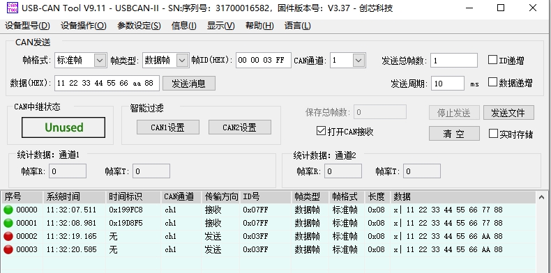
- CAN analyzer test results: