HOME
Shop
  • English
  • 简体中文
HOME
Shop
  • English
  • 简体中文
  • Product Series

    • FPGA+ARM

      • GM-3568JHF

        • 1. Introduction

          • About GM-3568JHF
        • 2. Quick Start

          • 00 Introduction
          • 01 Environment Setup
          • 02 Compilation Instructions
          • 03 Flashing Guide
          • 04 Debug Tools
          • 05 Software Update
          • 06 View Information
          • 07 Test Commands
          • 08 App Compilation
          • 09 Source Code Acquisition
        • 3. Peripherals and Interfaces

          • 01 USB
          • 02 Display and Touch
          • 03 Ethernet
          • 04 WIFI
          • 05 Bluetooth
          • 06 TF-Card
          • 07 Audio
          • 08 Serial Port
          • 09 CAN
          • 10 RTC
        • 4. Application Development

          • 01 UART read and write case
          • 02 Key detection case
          • 03 LED light flashing case
          • 04 MIPI screen detection case
          • 05 Read USB device information example
          • 06 FAN Detection Case
          • 07 FPGA FSPI Communication Case
          • 08 FPGA DMA read and write case
          • 09 GPS debugging case
          • 10 Ethernet Test Cases
          • 11 RS485 reading and writing examples
          • 12 FPGA IIC read and write examples
          • 13 PN532 NFC card reader case
          • 14 TF card reading and writing case
        • 5. QT Development

          • 01 ARM64 cross compiler environment construction
          • 02 QT program added automatic startup service
        • 6. RKNN_NPU Development

          • 01 RK3568 NPU Overview
          • 02 Development Environment Setup
          • Run Official YOLOv5 Example
          • Model Conversion Detailed Explanation
          • Run Custom Model on Board
        • 7. FPGA Development

          • ARM and FPGA Communication
          • /fpga-arm/GM-3568JHF/FPGA/ch02-FPGA-Development-Manual.html
        • 8. Others

          • 01 Modification of the root directory file system
          • 02 System auto-start service
        • 9. Download

          • Download Resources
    • ShimetaPi

      • M4-R1

        • 1. Introduction

          • 1.1 About M4-R1
        • 2. Quick Start

          • 2.1 OpenHarmony Overview
          • 2.2 Image Burning
          • 2.3 Development Environment Preparation
          • 2.4 Hello World Application
        • 3. Application Development

          • 3.1 Getting Started

            • 3.1.1 ArkTS Language Overview
            • 3.1.2 UI Components (Part 1)
            • 3.1.3 UI Components (Part 2)
            • 3.1.4 UI Components (Part 3)
          • 3.2 Advanced

            • 3.2.1 Getting Started Guide
            • 3.2.2 Usage of Third Party Libraries
            • 3.2.3 Deployment of the Application
            • 3.2.4 Factory Reset
            • 3.2.5 System Debug
            • 3.2.6 APP Stability Testing
            • 3.2.7 Application Testing
          • 3.3 Getting Docs

            • 3.3.1 Official Website Information
          • 3.4 Development Instructions

            • 3.4.1 Full SDK
            • 3.4.2 Introduction of Third Party Libraries
            • 3.4.3 Introduction of HDC Tool
            • 3.4.4 Restore Factory Mode
            • 3.4.5 Update System API
          • 3.5 First Application

            • 3.5.1 First ArkTS App
          • 3.6 Application Demo

            • 3.6.1 UART Tool
            • 3.6.2 Graphics Tablet
            • 3.6.3 Digital Clock
            • 3.6.4 WIFI Tool
        • 4. Device Development

          • 4.1 Ubuntu Environment Development

            • 4.1.1 Environment Setup
            • 4.1.2 Download Source Code
            • 4.1.3 Compile Source Code
          • 4.2 Using DevEco Device Tool

            • 4.2.1 Tool Introduction
            • 4.2.2 Environment Construction
            • 4.2.3 Import SDK
            • 4.2.4 Function Introduction
        • 5. Peripherals and Interfaces

          • 5.1 Raspberry Pi Interfaces
          • 5.2 GPIO Interface
          • 5.3 I2C Interface
          • 5.4 SPI Communication
          • 5.5 PWM Control
          • 5.6 Serial Port Communication
          • 5.7 TF Card Slot
          • 5.8 Display Screen
          • 5.9 Touch Screen
          • 5.10 Audio
          • 5.11 RTC
          • 5.12 Ethernet
          • 5.13 M.2
          • 5.14 MINI PCIE
          • 5.15 Camera
          • 5.16 WIFI BT
          • 5.17 HAT
        • 6. FAQ

          • 6.1 Download Link
      • M5-R1

        • 1. Introduction

          • M5-R1 Development Documentation
        • 2. Quick Start

          • OpenHarmony Overview
          • Image Burning
          • Development Environment Preparation
          • Hello World Application and Deployment
        • 3. Peripherals and Interfaces

          • 3.1 Raspberry Pi Interfaces
          • 3.2 GPIO Interface
          • 3.3 I2C Interface
          • 3.4 SPI Communication
          • 3.5 PWM Control
          • 3.6 Serial Port Communication
          • 3.7 TF Card Slot
          • 3.8 Display Screen
          • 3.9 Touch Screen
          • 3.10 Audio
          • 3.11 RTC
          • 3.12 Ethernet
          • 3.13 M.2
          • 3.14 MINI PCIE
          • 3.15 Camera
          • 3.16 WIFI BT
          • 3.17 HAT
        • 4. Application Development

          • 4.1 Getting Started

            • 4.1.1 ArkTS Language Overview
            • 4.1.2 UI Components (Part 1)
            • 4.1.3 UI Components (Part 2)
            • 4.1.4 UI Components (Part 3)
          • 4.2 Advanced

            • 4.2.1 Getting Started Guide
            • 4.2.2 Usage of Third Party Libraries
            • 4.2.3 Deployment of the Application
            • 4.2.4 Factory Reset
            • 4.2.5 System Debug
            • 4.2.6 APP Stability Testing
            • 4.2.7 Application Testing
        • 5. Device Development

          • 5.1 Environment Setup
          • 5.2 Download Source Code
          • 5.3 Compile Source Code
        • 6. Download

          • Data Download
    • OpenHarmony

      • SC-3568HA

        • 1. Introduction

          • 1.1 About SC-3568HA
        • 2. Quick Start

          • 2.1 OpenHarmony Overview
          • 2.2 Image Burning
          • 2.3 Development Environment Preparation
          • 2.4 Hello World Application
        • 3. Application Development

          • 3.1 ArkUI

            • 3.1.1 ArkTS Language Overview
            • 3.1.2 UI Components (Part 1)
            • 3.1.3 UI Components (Part 2)
            • 3.1.4 UI Components (Part 3)
          • 3.2 Advanced

            • 3.2.1 Getting Started Guide
            • 3.2.2 Usage of Third Party Libraries
            • 3.2.3 Deployment of the Application
            • 3.2.4 Factory Reset
            • 3.2.5 System Debug
            • 3.2.6 APP Stability Testing
            • 3.2.7 Application Testing
        • 4. Device Development

          • 4.1 Environment Setup
          • 4.2 Download Source Code
          • 4.3 Compile Source Code
        • 5. Peripherals and Interfaces

          • 5.1 Raspberry Pi Interfaces
          • 5.2 GPIO Interface
          • 5.3 I2C Interface
          • 5.4 SPI Communication
          • 5.5 PWM Control
          • 5.6 Serial Port Communication
          • 5.7 TF Card Slot
          • 5.8 Display Screen
          • 5.9 Touch Screen
          • 5.10 Audio
          • 5.11 RTC
          • 5.12 Ethernet
          • 5.13 M.2
          • 5.14 MINI PCIE
          • 5.15 Camera
          • 5.16 WIFI BT
          • 5.17 HAT
        • 6. FAQ

          • 6.1 Download Link
      • M-K1HSE

        • 1. Introduction

          • 1.1 Product Introduction
        • 2. Quick Start

          • 2.1 Debug Tool Installation
          • 2.2 Development Environment Setup
          • 2.3 Source Code Download
          • 2.4 Build Instructions
          • 2.5 Flashing Guide
          • 2.6 APT Update Sources
          • 2.7 View Board Info
          • 2.8 CLI LED and Key Test
          • 2.9 GCC Build Programs
        • 3. Application Development

          • 3.1 Basic Application Development

            • 3.1.1 Development Environment Preparation
            • 3.1.2 First Application HelloWorld
            • 3.1.3 Develop HAR Package
          • 3.2 Peripheral Application Cases

            • 3.2.1 UART Read/Write
            • 3.2.2 Key Demo
            • 3.2.3 LED Flash
        • 4. Peripherals and Interfaces

          • 4.1 Standard Peripherals

            • 4.1.1 USB
            • 4.1.2 Display and Touch
            • 4.1.3 Ethernet
            • 4.1.4 WIFI
            • 4.1.5 Bluetooth
            • 4.1.6 TF Card
            • 4.1.7 Audio
            • 4.1.8 Serial Port
            • 4.1.9 CAN
            • 4.1.10 RTC
          • 4.2 Interfaces

            • 4.2.1 Audio
            • 4.2.2 RS485
            • 4.2.3 Display
            • 4.2.4 Touch
        • 5. System Customization Development

          • 5.1 System Porting
          • 5.2 System Customization
          • 5.3 Driver Development
          • 5.4 System Debugging
          • 5.5 OTA Upgrade
        • 6. Download

          • 6.1 Download
    • EVS-Camera

      • CF-NRS1

        • 1. Introduction

          • 1.1 About CF-NRS1
          • 1.2 Event-Based Concepts
          • 1.3 Quick Start
          • 1.4 Resources
        • 2. Development

          • 2.1 Development Overview

            • 2.1.1 Shimetapi Hybrid Camera SDK Introduction
          • 2.2 Environment & API

            • 2.2.1 Environment Overview
            • 2.2.2 Development API Overview
          • 2.3 Linux Development

            • 2.3.1 Linux SDK Introduction
            • 2.3.2 Linux SDK API
            • 2.3.3 Linux Algorithm
            • 2.3.4 Linux Algorithm API
          • 2.4 Service & Web

            • 2.4.1 EVS Server
            • 2.4.2 Time Server
            • 2.4.3 EVS Web
        • 3. Download

          • 3.1 Download
        • 4. Common Problems

          • 4.1 Common Problems
      • CF-CRA2

        • 1. Introduction

          • 1.1 About CF-CRA2
        • 2. Download

          • 2.1 Download
      • EVS Module

        • 1. Related Concepts
        • 2. Hardware Preparation and Environment Configuration
        • 3. Example Program User Guide
        • Resources Download
    • AI-model

      • 1684XB-32T

        • 1. Introduction

          • AIBOX-1684XB-32 Introduction
        • 2. Quick Start

          • First time use
          • Network Configuration
          • Disk usage
          • Memory allocation
          • Fan Strategy
          • Firmware Upgrade
          • Cross-Compilation
          • Model Quantization
        • 3. Application Development

          • 3.1 Development Introduction

            • Sophgo SDK Development
            • SOPHON-DEMO Introduction
          • 3.2 Large Language Models

            • Deploying Llama3 Example
            • /ai-model/AIBOX-1684XB-32/application-development/LLM/Sophon_LLM_api_server-Development-AIBOX-1684XB-32.html
            • /ai-model/AIBOX-1684XB-32/application-development/LLM/MiniCPM-V-2_6-AIBOX-1684XB-32.html
            • /ai-model/AIBOX-1684XB-32/application-development/LLM/Qwen-2-5-VL-demo-Development-AIBOX-1684XB-32.html
            • /ai-model/AIBOX-1684XB-32/application-development/LLM/Qwen-3-chat-demo-Development-AIBOX-1684XB-32.html
            • /ai-model/AIBOX-1684XB-32/application-development/LLM/Qwen3-Qwen Agent-MCP.html
            • /ai-model/AIBOX-1684XB-32/application-development/LLM/Qwen3-langchain-AI Agent.html
          • 3.3 Deep Learning

            • ResNet (Image Classification)
            • LPRNet (License Plate Recognition)
            • SAM (Universal Image Segmentation Foundation Model)
            • YOLOv5 (Object Detection)
            • OpenPose (Human Keypoint Detection)
            • PP-OCR (Optical Character Recognition)
        • 4. Download

          • Resource Download
      • 1684X-416T

        • 1. Introduction

          • AIBOX-1684X-416 Introduction
        • 2. Demo Simple Operation Guide

          • Simple instructions for using shimeta smart monitoring demo
      • RDK-X5

        • 1. Introduction

          • RDK-X5 Hardware Introduction
        • 2. Quick Start

          • RDK-X5 Quick Start
        • 3. Application Development

          • 3.1 AI Online Model Development

            • AI Online Development - Experiment01
            • AI Online Development - Experiment02
            • AI Online Development - Experiment03
            • AI Online Development - Experiment04
            • AI Online Development - Experiment05
            • AI Online Development - Experiment06
          • 3.2 Large Language Models (Voice)

            • Voice LLM Application - Experiment01
            • Voice LLM Application - Experiment02
            • Voice LLM Application - Experiment03
            • Voice LLM Application - Experiment04
            • Voice LLM Application - Experiment05
            • Voice LLM Application - Experiment06
          • 3.3 40pin-IO Development

            • 40pin IO Development - Experiment01
            • 40pin IO Development - Experiment02
            • 40pin IO Development - Experiment03
            • 40pin IO Development - Experiment04
            • 40pin IO Development - Experiment05
            • 40pin IO Development - Experiment06
            • 40pin IO Development - Experiment07
          • 3.4 USB Module Development

            • USB Module Usage - Experiment01
            • USB Module Usage - Experiment02
          • 3.5 Machine Vision

            • Machine Vision Technology Development - Experiment01
            • Machine Vision Technology Development - Experiment02
            • Machine Vision Technology Development - Experiment03
            • Machine Vision Technology Development - Experiment04
          • 3.6 ROS2 Base Development

            • ROS2 Basic Development - Experiment01
            • ROS2 Basic Development - Experiment02
            • ROS2 Basic Development - Experiment03
            • ROS2 Basic Development - Experiment04
      • RDK-S100

        • 1. Introduction

          • 1.1 About RDK-S100
        • 2. Quick Start

          • 2.1 First Use
        • 3. Application Development

          • 3.1 AI Online Model Development

            • 3.1.1 Volcano Engine Doubao AI
            • 3.1.2 Image Analysis
            • 3.1.3 Multimodal Visual Analysis
            • 3.1.4 Multimodal Image Comparison
            • 3.1.5 Multimodal Document Analysis
            • 3.1.6 Camera AI Vision Analysis
          • 3.2 Large Language Models

            • 3.2.1 Speech Recognition
            • 3.2.2 Voice Conversation
            • 3.2.3 Multimodal Image Analysis
            • 3.2.4 Multimodal Image Comparison
            • 3.2.5 Multimodal Document Analysis
            • 3.2.6 Multimodal Vision Application
          • 3.3 40pin-IO Development

            • 3.3.1 GPIO Output LED Blink
            • 3.3.2 GPIO Input
            • 3.3.3 Key Control LED
            • 3.3.4 PWM Output
            • 3.3.5 Serial Output
            • 3.3.6 I2C Experiment
          • 3.4 USB Module Development

            • 3.4.1 USB Voice Module
            • 3.4.2 Sound Source Localization
          • 3.5 Machine Vision

            • 3.5.1 USB Camera
            • 3.5.2 Image Processing Basics
            • 3.5.3 Object Detection
            • 3.5.4 Image Segmentation
          • 3.6 ROS2 Base Development

            • 3.6.1 Environment Setup
            • 3.6.2 Create and Build Workspace
            • 3.6.3 ROS2 Topic Communication
            • 3.6.4 ROS2 Camera Application
    • Core-Board

      • C-3568BQ

        • 1. Introduction

          • C-3568BQ Introduction
      • C-3588LQ

        • 1. Introduction

          • C-3588LQ Introduction
      • GC-3568JBAF

        • 1. Introduction

          • GC-3568JBAF Introduction
      • C-K1BA

        • 1. Introduction

          • C-K1BA Introduction

06 FAN Detection Case

1 Case Introduction

This case aims to introduce how to test the fan interface on the development board to control the fan start, stop and speed regulation functions.

2 FAN Interface Introduction

The FAN interface on the development board is a 4P interface, but only three ports are functional, namely 12V, PWM, and GND. The fan is debugged through PWM signal control.

3 Operation process

Open the terminal and copy the executable program smdt_fan_demo in the bin directory of this case (05-Development Materials\Software Development Materials\linux_demo\smdt_fan_demo\bin) to the development board file system (the source code can be viewed in the src path).

Optional operation: Because the development board is equipped with a wireless network card, if the terminal keeps displaying the log information generated by the wireless network card driver, you can modify the display level of the Linux kernel log by using the following code.

#修改 Linux 内核日志的显示级别,内核的日志级别被设置为只显示紧急或更高级别的消息
echo 1 4 1 7 > /proc/sys/kernel/printk

First check if the PWM device is exported. If it is not exported, we need to export the PWM device. Here we select the device pwmchip0 to export the first channel (pwm0)

#检查 /sys/class/pwm/pwmchip0 目录中是否有 pwm0
ls /sys/class/pwm/pwmchip0

#若没有,则导出 PWM 设备
echo 0 > /sys/class/pwm/pwmchip0/export

#再次检查是否成功导出 PWM 设备
ls /sys/class/pwm/pwmchip0

Execute the following command in the terminal to switch to the directory where the smdt_fan_demo executable program is located

#切换到 smdt_fan_demo 可执行程序所在目录
cd ‘可执行文件所在目录’

#查看 smdt_fan_demo 是否在该目录下
ls

If the executable file smdt_fan_demo is in the current directory, modify the permissions of the executable file

#修改文件权限
chmod 777 smdt_fan_demo

#查询是否修改成功
ls -ld smdt_fan_demo

After confirming that the file modification permission is successful, execute ./smdt_fan_demo -h to view the help information of the program. The default parameters of some settings in this test script are as follows: period: 200000, that is, the PWM waveform period is 200ms polarity: normal In this mode, duty_cycle represents the duration of the high level in one cycle.

#查看帮助信息
./smdt_fan_demo -h

The execution result is as follows:

FAN_1

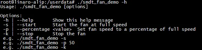
Enter the following command to test the start, stop and speed regulation of the fan.

#查看帮助信息
#风扇启动
./smdt_fan_demo -s

#风扇调速
./smdt_fan_demo -p 50		#50%占空比

#风扇停止
./smdt_fan_demo -k

Fan startup execution result:

FAN_2

The fan is set to 50% duty cycle execution result:

FAN_3

Fan stop execution result:

FAN_4
Edit this page on GitHub
Last Updated:
Contributors: zsl, zwhuang
Prev
05 Read USB device information example
Next
07 FPGA FSPI Communication Case