13 PN532 NFC card reader case
1 Case Introduction
This case aims to introduce how to use the PN532 NFC card to obtain the water drop card ID through the 40PIN Raspberry Pi interface.
2 Module Introduction
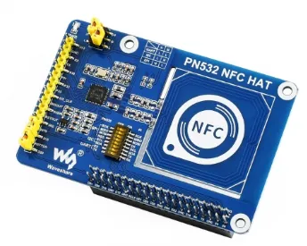
PN532 NFC HAT is an NFC expansion board designed for Raspberry Pi. It uses PN532 as the main controller and supports I2C, SPI and serial port communications. It can expand the NFC communication function of Raspberry Pi.
3 Mode Switching Introduction
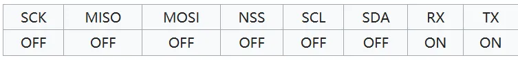
3.1 Serial communication mode
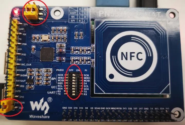
Use jumper caps to set I0 to L, l1 to L. Use jumper caps to connect RSTPDN -> D20. Set the dip switch to
3.2 SPI Communication Mode
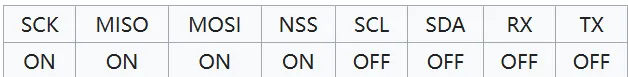
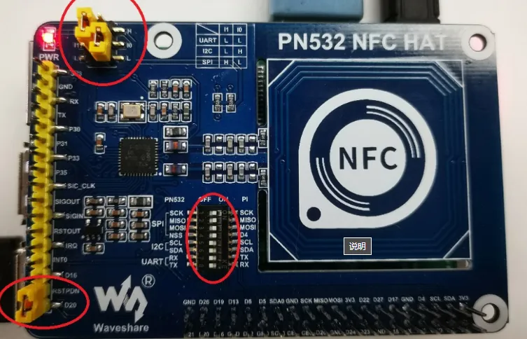
Use the jumper cap to set I0 to L and l1 to H. Connect RSTPDN with the jumper cap -> D20 and set the dip switch to
3.3 I2C Communication Mode
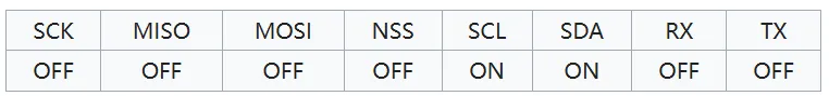
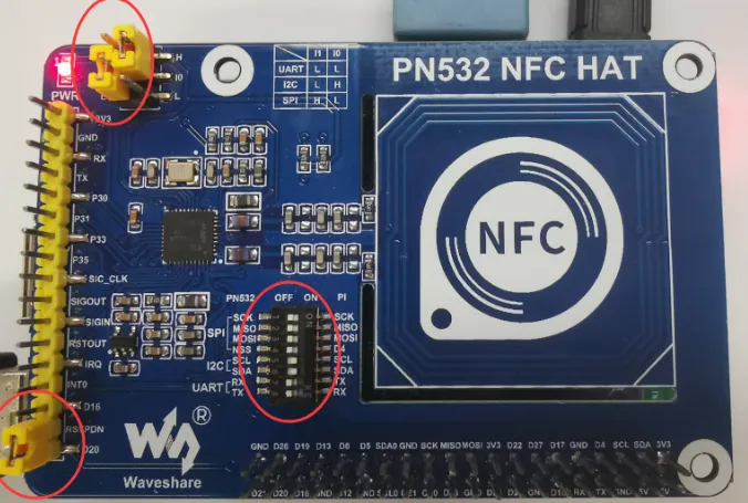
Use jumper caps to set I0 to H and I1 to L. Use jumper caps to connect RSTPDN -> D20 and INT0 -> D16 (to avoid Clock Stretching). Set the DIP switch to
4 Operation process
4.1 Serial communication mode
Open the terminal and copy the executable program smdt_nfc_demo in the bin directory of this case (05-Development Materials\Software Development Materials\linux_demo\smdt_nfc_demo\bin) to the development board file system (the source code can be viewed in the src path).
Execute the following command in the terminal to switch to the directory where the smdt_nfc_demo executable program is located
#切换到 smdt_nfc_demo  可执行程序所在目录
cd ‘the file's directory’

#查看 smdt_nfc_demo  是否在该目录下
ls
If the executable file smdt_nfc_demo is in the current directory, modify the permissions of the executable file.
#添加可执行权限
chmod +x smdt_nfc_demo
#查询是否修改成功
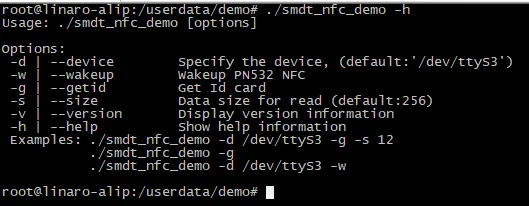
ls -ld smdt_nfc_demoAfter confirming that the file modification permission is successful, execute ./smdt_nfc_demo -h to view the help information of the program. The default parameters of some settings in this test script are as follows:
device: /dev/ttyS3, i.e. UART3
#查看帮助信息
./smdt_nfc_demo -h
The execution result is as follows:
Enter the following command to switch the mode
#PN532 NFC唤醒模式
./smdt_nfc_demo -w
#RPN532 读卡ID模式
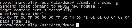
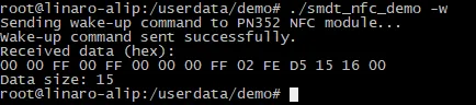
./smdt_nfc_demo -rExecute ./smdt_nfc_demo -w to enter the PN532 NFC module wake-up mode and return a wake-up response frame. The execution results are as follows:
Enter Ctrl+Z to force exit this mode.
Execute ./smdt_nfc_demo -r to enter the PN532 NFC module card ID reading mode. After reading the card ID, the response frame corresponding to the card ID will be displayed on the terminal. The execution results are as follows:
Enter Ctrl+Z to force exit this mode.