11 RS485 reading and writing examples
1 Case Introduction
This case aims to introduce how to test the read and write functions of RS485 on the development board.
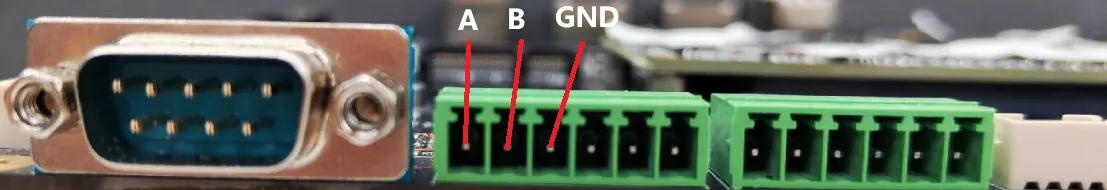
2 RS485 interface introduction
There are two RS485 interfaces on the development board, corresponding to UART7 and UART8 respectively. The interface wiring diagram corresponding to UART7 is as follows:
3 Operation process
Open the terminal and copy the executable program smdt_rs485_rw in the bin directory of this case (05-Development Materials\Software Development Materials\linux_demo\smdt_rs485_rw\bin) to the development board file system (the source code can be viewed in the src path).
Execute the following command in the terminal and switch to the directory where the smdt_rs485_rw executable program is located.
#切换到 smdt_rs485_rw  可执行程序所在目录
cd ‘the file's directory’

#查看 smdt_rs485_rw  是否在该目录下
ls
If the executable file smdt_rs485_rw is in the current directory, modify the permissions of the executable file.
#添加可执行权限
chmod +x smdt_rs485_rw
#查询是否修改成功
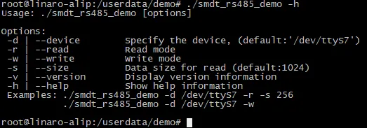
ls -ld smdt_rs485_rwAfter confirming that the file modification permission is successful, execute ./smdt_rs485_rw -h to view the help information of the program. The default parameters of some settings in this test script are as follows: device: /dev/ttyS7, i.e. UART4 size: 1024, i.e. the default length of the received data in read mode is 1024
#查看帮助信息
./smdt_rs485_rw -h
The execution result is as follows:
Enter the following commands, which are read mode and receive mode respectively
#RS485读取数据模式
./smdt_rs485_rw -d /dev/ttyS7 -r
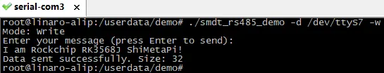
#RS485发送数据模式
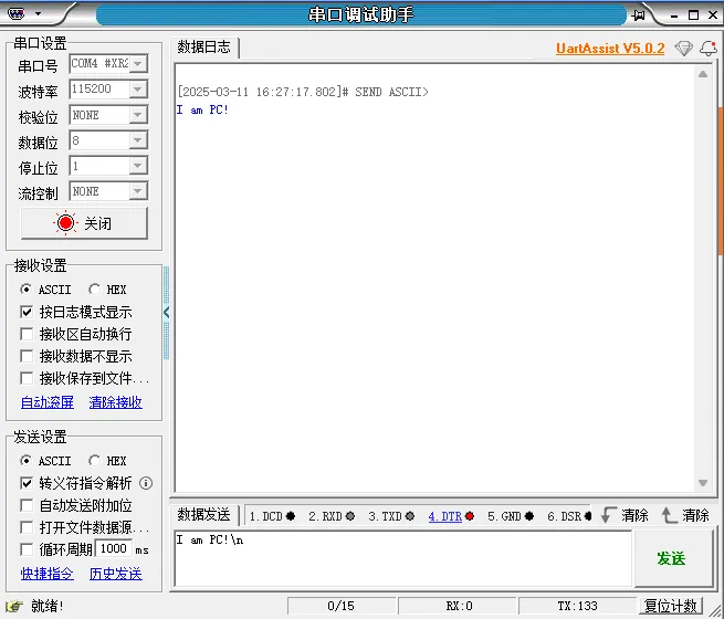
./smdt_rs485_rw -d /dev/ttyS7 -wExecute ./smdt_rs485_rw -d /dev/ttyS7 -w , it will enter the send input state, and send data when the Enter key is pressed. The execution results are as follows:
Enter Ctrl+Z to force exit this mode.
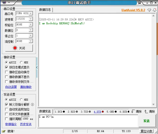
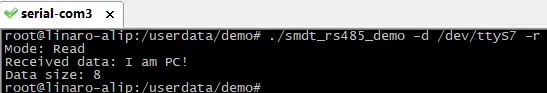
Execute ./smdt_rs485_rw -d /dev/ttyS7 -r to enter the data receiving mode, receive data and stop receiving when the Enter key is pressed or the data size exceeds the limit, and display the data in the terminal window. The execution results are as follows:
Enter Ctrl+Z to force exit this mode.
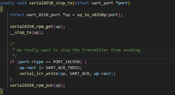
4 Supplementary Notes
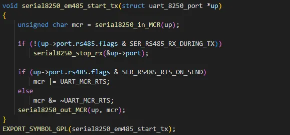
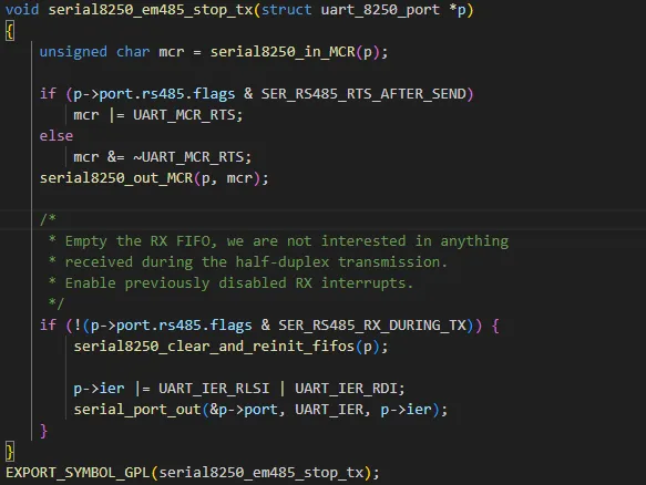
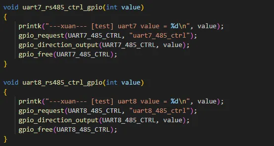
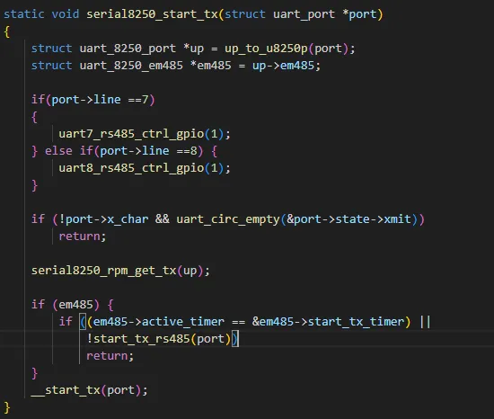
The switching of RS485's sending and receiving modes has been integrated into the kernel driver, and the user does not need to manually control the GPIO switching . Some kernel driver codes for automatic switching of RS485 modes are as follows: