03 LED light flashing case
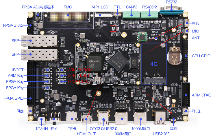
In this case, the LED flashing effect is achieved by repeatedly writing 1 and 0 values to the evaluation board user programmable indicator LED device node. The LED on and off time is 0.5s. The LED light is located in the red box in the figure below.
LED Light Basic Control
Enter the following command in the terminal to view all LED light device files.
cd /sys/class/leds/
ls
Enter the directory of a specific LED device, for example, view the information of user-led1.
cd cd user-led1
ls
Enter the following command to light up the corresponding LED light, where 1 means it is on and 0 means it is off.
echo 1 > brightnessOperation process
Copy the executable program smdt_led_demo in the bin directory of this case (05-Development Materials\Software Development Materials\linux_demo\smdt_led_demo\bin) to the development board file system (the source code can be viewed in the src path).
Execute the following command in the terminal to switch to the directory where the smdt_led_demo executable program is located.
cd ‘the file's directory’After switching, you can run the command "ls" to check whether the smdt_led_demo executable program is in the current directory.
lsIf the executable file smdt_led_demo exists in the current directory, continue to perform the following operations: Enter the following command to modify the file permissions.
chmod 777 smdt_led_demoAfter modifying the permissions, you can enter the following command to check whether the modification is successful.
ls -ld smdt_led_demoThe execution result is: -rwxrwxrwx 1 root root 13824 Mar 4 01:22 smdt_led_demo
-rwxrwxrwx means the permissions have been modified successfully, the file can be executed, and you can continue with the following operations.
Enter the following command:
./led_flash -help
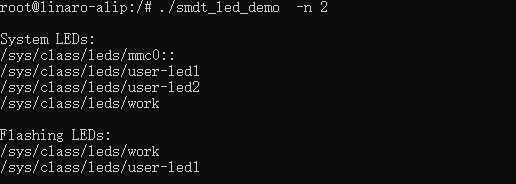
./led_flash -n 2The green LED light on the development board flashes at a time interval of 0.5s. At the same time, the serial terminal prints the system's entire LED device information and the LED device information currently controlled by the program.
Press Ctrl+C to exit the test.