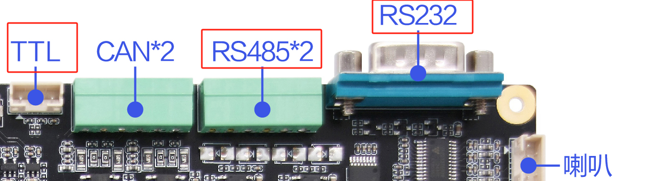
Serial Port
There are a total of 6 serial ports coming out of RK3568 on the development board
- RS232:1
- RS485:2
- TTL:2 (one of which is on the 40PIN interface, which can be connected to the Raspberry Pi expansion board for RS485 use)
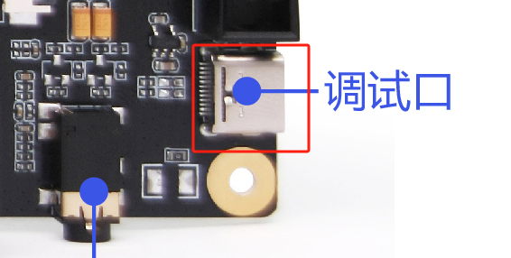
- Type C (Debug): 1 (This interface is a USB to TTL interface and can be used directly after connecting to Type C)
Connecting to the Serial Port
Different interfaces have different corresponding connection methods. The following are the connection methods of different serial ports.
TTL
Take the USB to TTL tool as an example:
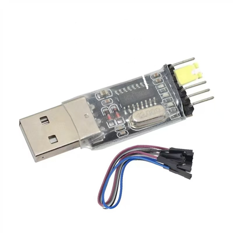
- TXD -- RXD
- RXD -- TXD
- GND -- GND
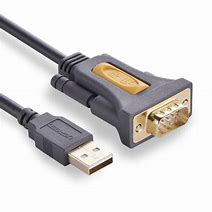
RS232
Take the USB to 232 tool as an example:
Because it is a standard 232 interface, you can connect directly
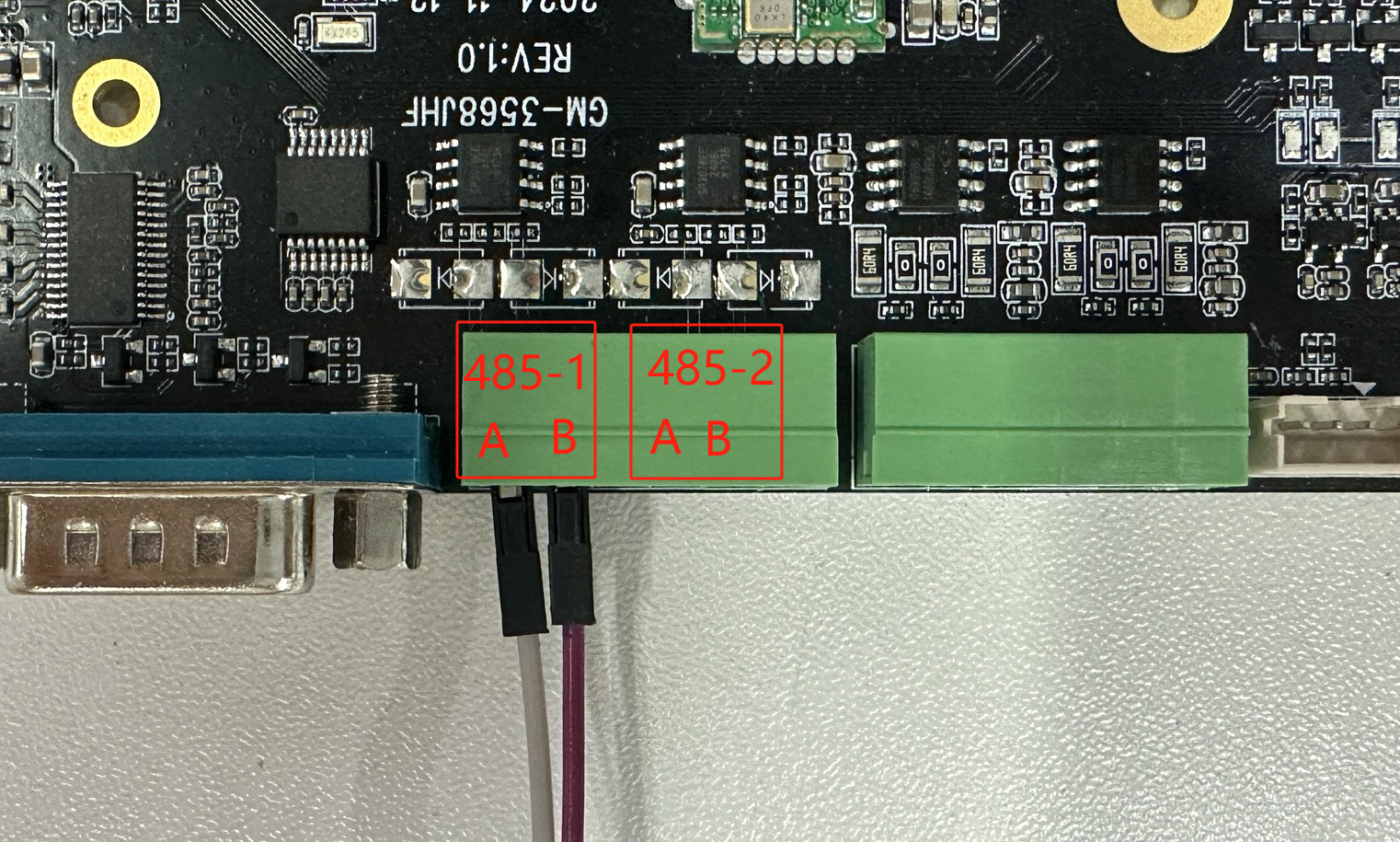
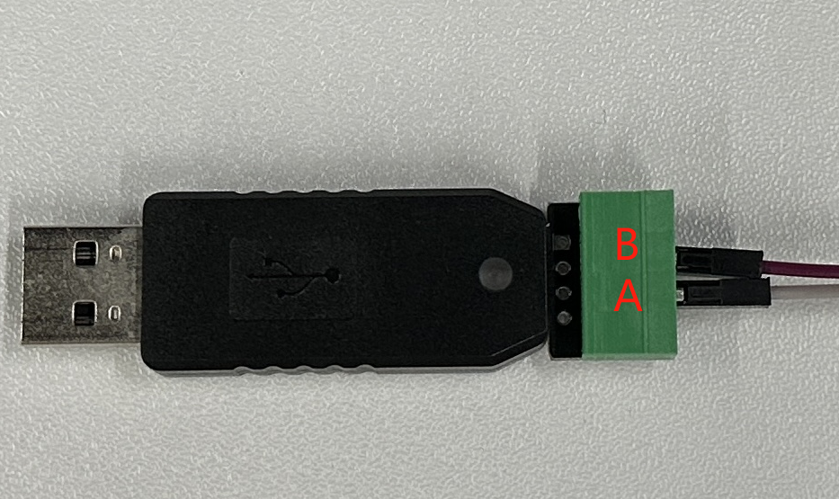
RS485
Take the USB to 485 tool as an example:
USB to 485- A -> Development Board- A
USB to 485- B -> Development Board- B
As shown in the figure:
Serial communication test
We use the TTL serial port on the board to conduct experiments. The corresponding device file is /dev/ttyS4. By directly reading and writing the tty device file, we can control the device to receive or send data through the serial port. Below we use the board with the serial port debugging assistant under Windows.
Tips
The RS485 serial port has added the function of automatically switching directions at the driver layer, and the communication is the same as that of the ordinary serial port
Query serial port parameters and modify baud rate
Use the stty tool to query serial port parameters
#在开发板的终端执行如下命令
root@linaro-alip:/# stty -F /dev/ttyS4
speed 9600 baud; line = 0;
-brkint -imaxbel
Use the stty tool to modify serial port parameters
#设置通讯速率,其中ispeed为输入速率,ospeed为输出速率
root@linaro-alip:/# stty -F /dev/ttyS4 ispeed 115200 ospeed 115200
root@linaro-alip:/# stty -F /dev/ttyS4
speed 115200 baud; line = 0;
-brkint -imaxbel
Communication with PC
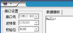
After configuring the serial port debugging assistant on the PC, use the following command on the board to test the serial port sending data:
- Sending data:
#在板卡上的终端执行如下指令
#使用echo命令向终端设备文件写入字符串"Hello!"
echo Hello! > /dev/ttyS4
The serial port debugging assistant on the PC will receive the content
- Receiving data:
To test receiving data, you can use the microcom tool:
#在板卡上的终端执行如下指令
#使用microcom命令读取终端设备文件,-s参数可以设置波特率
busybox microcom -s 115200 /dev/ttyS4
Hello World! #PC发送过来的数据
#microcom命令会等待
#使用串口调试助手发送字符串
#板卡的终端会输出接收到的内容