HOME
Shop
  • English
  • 简体中文
HOME
Shop
  • English
  • 简体中文
  • Product Series

    • FPGA+ARM

      • GM-3568JHF

        • 1. Introduction

          • GM-3568JHF Introduction
        • 2. Quick Start

          • 01 Environment Construction
          • 02 Compilation Instructions
          • 03 Burning Guide
          • 04 Debugging Tools
          • 05 Software Update
          • 06 View information
          • 07 Test Command
          • 08 Application Compilation
          • 09 Source code acquisition
        • 3. Peripherals and Interfaces

          • USB
          • Display and touch
          • Ethernet
          • WIFI
          • Bluetooth
          • TF-Card
          • Audio
          • Serial Port
          • CAN
          • RTC
        • 4. Application Development

          • 01 UART read and write case
          • 02 Key detection case
          • 03 LED light flashing case
          • 04 MIPI screen detection case
          • 05 Read USB device information example
          • 06 FAN Detection Case
          • 07 FPGA FSPI Communication Case
          • 08 FPGA DMA read and write case
          • 09 GPS debugging case
          • 10 Ethernet Test Cases
          • 11 RS485 reading and writing examples
          • 12 FPGA IIC read and write examples
          • 13 PN532 NFC card reader case
          • 14 TF card reading and writing case
        • 5. QT Development

          • 01 ARM64 cross compiler environment construction
          • 02 QT program added automatic startup service
        • 6. Others

          • 01 Modification of the root directory file system
          • 02 System auto-start service
    • ShimetaPi

      • M4-R1

        • Introduction

          • M4-R1 Introduction
        • Get started quickly

          • OpenHarmony概述
          • 镜像烧录
          • 开发环境准备
          • Hello World应用以及部署
        • Application Development

          • getting Started

            • 第一章 ArkTS语言简介
            • 第二章 UI组件介绍和实际应用(上)
            • 第三章 UI组件介绍和实际应用(中)
            • 第四章 UI组件介绍和实际应用(下)
          • Advanced

            • 第一章 入门指引
            • 第二章 三方库的引用和使用
            • 第三章 应用编译以及部署
            • 第四章 命令行恢复出厂设置
            • 第五章 系统调试--HDC调试
            • 第六章 APP 稳定性测试
            • 第七章 应用测试
        • Equipment Development

          • 第一章 环境搭建
          • 第二章 下载源码
          • 第三章 编译源码
        • Peripherals and interfaces

          • 树莓派接口
          • GPIO 接口
          • I2C 接口
          • SPI通信
          • PWM控制
          • 串口通讯
          • TF Card
          • 屏幕
          • 触摸
          • 音频
          • RTC
          • Ethernet
          • M.2
          • MINI-PCIE
          • Camera
          • WIFI&BT
          • 树莓派拓展板
        • Frequently asked questions

          • 资源下载
      • M5-R1

        • Introduction

          • Introduction to ShimetaPi M5-R1
    • OpenHarmony

      • SC-3568HA

        • Introduction

          • SC-3568HA Overview
        • Quick Start Guide

          • OpenHarmony Overview
          • Image Flashing
          • Setting Up the Development Environment
          • Hello World Application and Deployment
        • Application Development

          • ArkUI

            • Chapter 1 Introduction to ArkTS Language
            • Chapter 2 Introduction to UI Components and Practical Applications (Part 1)
            • Chapter 3 Introduction to UI Components and Practical Applications (Part 2)
            • Chapter 4 Introduction to UI Components and Practical Applications (Part 3)
          • Expand

            • Chapter 1 Getting Started Guide
            • Chapter 2 Referencing and Using Third-Party Libraries
            • Chapter 3: Application Compilation and Deployment
            • Chapter 4: Command-Line Factory Reset
            • Chapter 5: System Debugging -- HDC (Huawei Device Connector) Debugging
            • Chapter 6 APP Stability Testing
            • Chapter 7 Application Testing
        • Device Development

          • Chapter 1 Environment Setup
          • Chapter 2 Download Source Code
          • Chapter 3 Compiling Source Code
        • Peripheral And Iinterface

          • Raspberry Pi interface
          • GPIO Interface
          • I2C Interface
          • SPI communication
          • PWM (Pulse Width Modulation) control
          • Serial port communication
          • TF Card
          • Display Screen
          • Touch
          • Audio
          • RTC
          • Ethernet
          • M.2
          • MINI-PCIE
          • Camera
          • WIFI&BT
          • Raspberry Pi expansion board
        • Frequently Asked Questions

          • Resource Downloads
      • M-K1HSE

        • Introduction

          • M-K1HSE Introduction
        • Quick Start

          • Development environment construction
          • Source code acquisition
          • Compilation Notes
          • Burning Guide
        • Peripherals and interfaces

          • 01 Audio
          • 02 RS485
          • 03 Display
        • System customization development

          • System transplant
          • System customization
          • Driver Development
          • System Debugging
          • OTA Update
    • EVS-Camera

      • CF-NRS1

        • 1. Introduction

          • Event Camera Technical Documentation
        • 2. Quick Start

          • Host driver and software installation
        • 3. SDK application development

          • API Usage Instructions
      • CF-CRA2

        • Introduction

          • About CF-NRS1
    • AI-model

      • 1684XB-32T

        • Introduction

          • AIBOX-1684XB-32 Introduction
        • Get started quickly

          • First time use
          • Network Configuration
          • Disk usage
          • Memory allocation
          • Fan Strategy
          • Firmware Upgrade
        • Deployment Tutorial

          • Algorithm deployment
          • Deploy Llama3 Example
        • Application Development

          • Sophgo SDK Development
          • Sophon LLM_api_server development
          • Deploy MiniCPM-V-2_6
          • Qwen-2-5-VL Image and Video Recognition DEMO
          • Qwen3-chat-DEMO
          • Qwen3-Qwen Agent-MCP-Demo
          • Qwen3-langchain-AI Agent
      • 1684X-416T

        • Introduction

          • AIBOX-1684X-416 Introduction
        • Demo simple operation guide

          • Simple instructions for using shimeta smart monitoring demo
    • Core-Board

      • C-3568BQ

        • Introduction

          • C-3568BQ Overview
      • C-3588LQ

        • Introduction

          • C-3588LQ Introduction
      • GC-3568JBAF

        • Introduction

          • GC-3568JBAF Introduction
      • C-K1BA

        • Introduction

          • C-K1BA Introduction

Audio

Audio Interface Introduction

Several audio interfaces on the development board:

  • Audio input interface: headphone, MIC
  • Audio output interface: headphone, speaker, HDMI
AUDIO

Sound card device

Get a recording device

root@linaro-alip:/# arecord -l
**** List of CAPTURE Hardware Devices ****
card 0: rockchipes8388 [rockchip-es8388], device 0: dailink-multicodecs ES8388 HiFi-0 [dailink-multicodecs ES8388 HiFi-0]
  Subdevices: 0/1
  Subdevice #0: subdevice #0
  • card 0:Onboard audio processing chip rockchip-es8388, which leads to two recording interfaces, one for the onboard MIC and the other for the headphone MIC
  • Card 0 is the device registered in Linux. We can call these interfaces through the application

Get playback device

root@linaro-alip:/# aplay -l
**** List of PLAYBACK Hardware Devices ****
card 0: rockchipes8388 [rockchip-es8388], device 0: dailink-multicodecs ES8388 HiFi-0 [dailink-multicodecs ES8388 HiFi-0]
  Subdevices: 1/1
  Subdevice #0: subdevice #0
card 1: rockchiphdmi [rockchip,hdmi], device 0: rockchip,hdmi i2s-hifi-0 [rockchip,hdmi i2s-hifi-0]
  Subdevices: 1/1
  Subdevice #0: subdevice #0
  • card 0 : onboard audio processing chip rockchip-es8388

  • card 1 : HDMI audio output

Card 0 and card 1 are devices registered in Linux. We can call these interfaces through applications.

Sound card driver directory

View the sound card driver directory

root@linaro-alip:/# ls -l /dev/snd/
total 0
drwxr-xr-x  2 root root       80 Oct 10 17:40 by-path
crw-rw----+ 1 root audio 116,  4 Oct 10 17:40 controlC0
crw-rw----+ 1 root audio 116,  6 Oct 10 17:40 controlC1
crw-rw----+ 1 root audio 116,  3 Oct 10 17:40 pcmC0D0c
crw-rw----+ 1 root audio 116,  2 Oct 10 17:40 pcmC0D0p
crw-rw----+ 1 root audio 116,  5 Oct 10 17:40 pcmC1D0p
crw-rw----+ 1 root audio 116,  1 Oct 10 17:40 seq
crw-rw----+ 1 root audio 116, 33 Oct 10 17:40 timer
  • controlC0:used for sound card control. C0 stands for sound card 0, corresponding to the onboard audio processing chip rockchip-es8388 mentioned above.

  • controlC1:used for sound card control, C1 stands for sound card 1, corresponding to the HDMI sound output above.

  • pcmC0D0p:pcm device used for playback. The last "p" is the abbreviation of playback, which means playing sound.

  • pcmC0D0c:pcm device for recording. The last "c" is the abbreviation of capture, which means recording.

  • pcmC1D0p:pcm device used for playback. The last "p" is the abbreviation of playback, which means playing sound.

  • timer :timer

  • by-path: stores the corresponding relationship of devices

root@lubancat:~# ls -l /dev/snd/by-path/
total 0
lrwxrwxrwx 1 root root 12 Feb 14 18:11 platform-fd880000.usb-usb-0:1.4:1.2 -> ../controlC2
lrwxrwxrwx 1 root root 12 Feb 14 18:11 platform-hdmi-sound -> ../controlC0
lrwxrwxrwx 1 root root 12 Feb 14 18:11 platform-rk809-sound -> ../controlC1
root@lubancat:~#
  • You can see that there is a corresponding relationship between each control, and these corresponding relationships just correspond to card 0 and card 1 above.

Recording and playback

Command Line

recording

The recording uses the arecord command, as shown below:


#获取录音设备
arecord -l
#用声卡0录制10s音频
arecord -d 10 -D hw:0,0 -r 48000 -c 2 -f S16_LE -t wav /data/test_device.wav

Parameter details:

  • -d 10 : Set the recording duration to 10 seconds.
  • -D hw:0,0 : specifies the audio device. hw:0,0 means using the first device (0) of the first sound card (0)
  • -r 48000 : Set the sampling rate to 48000 Hz (i.e. 48 kHz)
  • -c 2 : Set the number of audio channels to 2 (stereo)
  • -fS16_LE : Set the audio format to 16-bit signed little endian format (Signed 16-bit Little Endian)
  • -t wav : Set the output file format to WAV
  • /data/test_device.wav specifies the path and name of the output file

Audio Playback

#获取播放设备
aplay -l
#用声卡0播放音频5s
aplay -Dhw:1,0 -d5 /data/test_device.wav

Parameter details:

  • -D hw:0,0 : specifies the audio device, indicating the use of the first device (0) of the first sound card (0)
  • -d 5 : Set the playback duration to 5 seconds
  • /data/test_device.wav : specifies the path of the audio file to be played

Record and play simultaneously

Using arecord and aplay

#使用card 0录制并使用card 0进行播放
arecord -f cd -Dhw:0 | aplay -Dhw:0

Desktop

recording

After ensuring that you are connected to the Internet, install the recording software

#安装软件
sudo apt install gnome-sound-recorder

Open the software

AUDIO_2

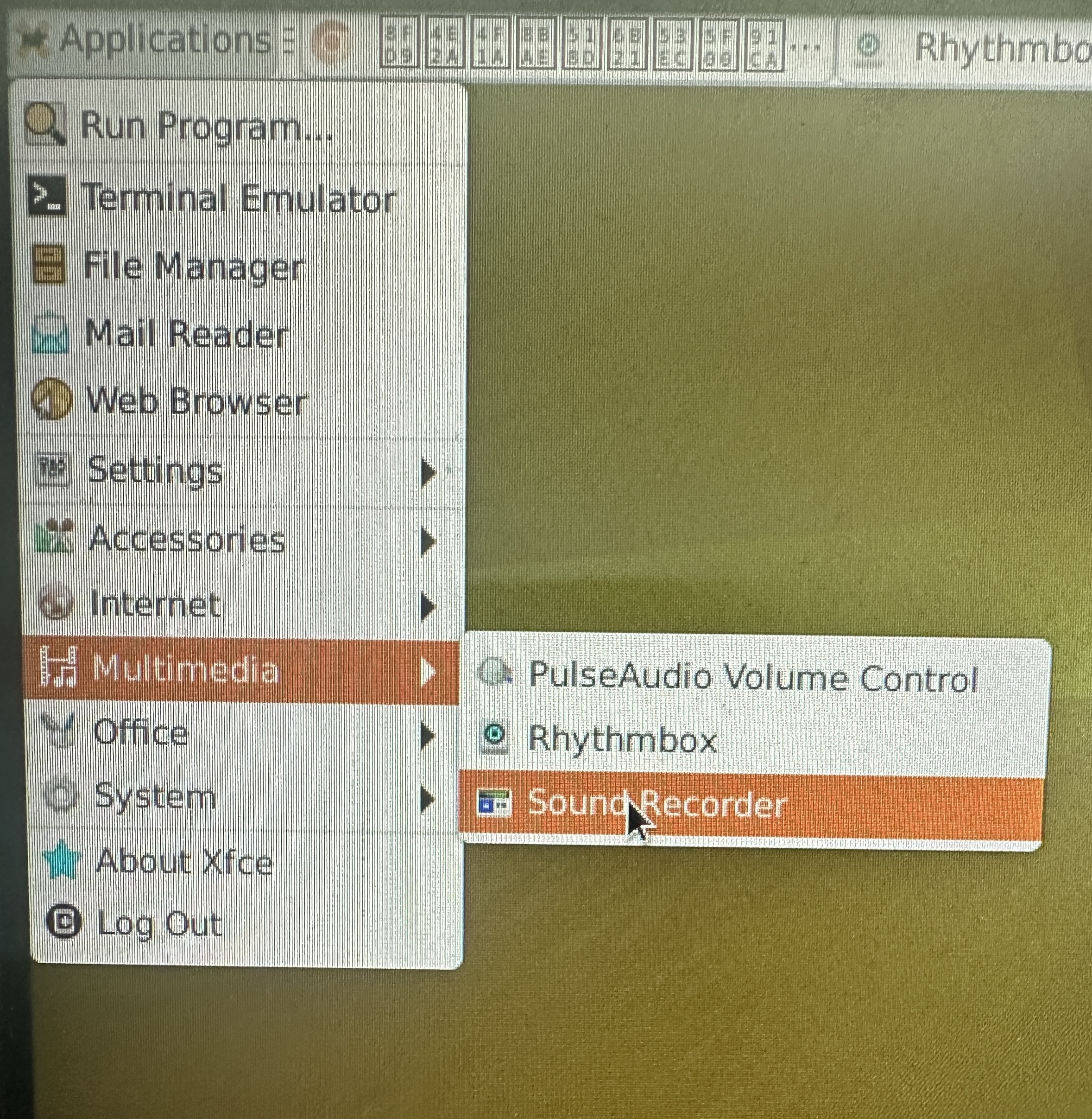
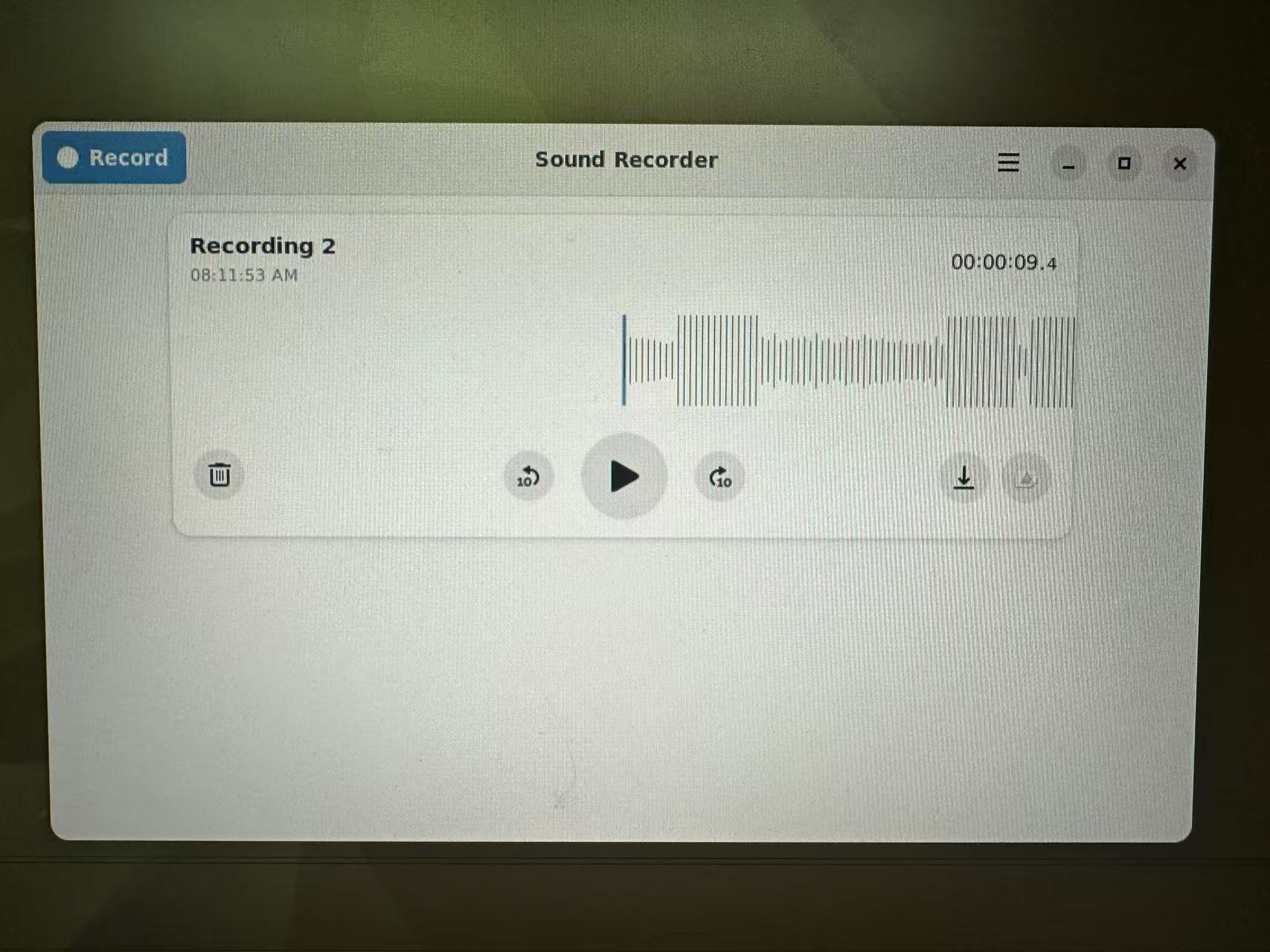
Click record in the upper left corner of the application to start recording, and press done to end recording. The recording path is /home/linaro/.local/share/org.gnome.SoundRecorder/. If there is nothing in the waveform during recording, check whether the following headphones are properly plugged in.

AUDIO_3

Play Music

The system comes with Rhythmbox. If you need other players, you can download them yourself.

AUDIO_5

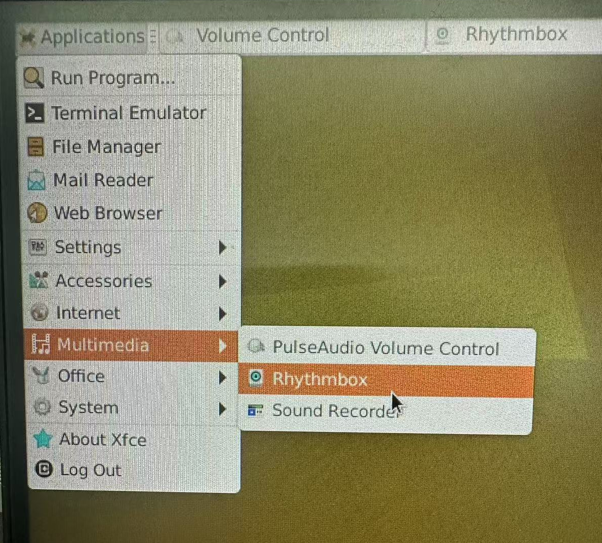
After opening, you need to import the audio, as shown in the figure:

AUDIO_6
Edit this page on GitHub
Last Updated:
Contributors: zsl, zwhuang
Prev
TF-Card
Next
Serial Port