09 GPS debugging case
1 Case Introduction
This case aims to introduce how to test the GPS function of obtaining positioning information.
2 GPS access development board
As shown in the figure, GPS can be connected to the TTL interface of the development board, namely UART4.

3 Operation process
Open the terminal and copy the executable program smdt_gps_demo in the bin directory of this case (05-Development Materials\Software Development Materials\linux_demo\smdt_gps_demo\bin) to the development board file system (the source code can be viewed in the src path).
Execute the following command in the terminal to switch to the directory where the smdt_gps_demo executable program is located
#切换到 smdt_gps_demo 可执行程序所在目录
cd ‘the file's directory’

#查看 smdt_gps_demo 是否在该目录下
ls
If the executable file smdt_gps_demo is in the current directory, modify the permissions of the executable file
#添加可执行权限
chmod +x smdt_gps_demo
#查询是否修改成功
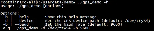
ls -ld smdt_gps_demoAfter confirming that the file modification permission is successful, execute ./smdt_gps_demo -h to view the help information of the program. The default parameters set in this test script are as follows: device: /dev/ttyS4 UART4 baud: 9600 The default baud rate is 9600
#查看帮助信息
./smdt_gps_demo -h
The execution result is as follows:
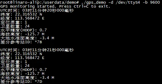
Enter the following command to obtain the current GPS data. If the positioning is successful, the coordinates and other data will be displayed. If the positioning is unsuccessful, a prompt will be displayed. Please check whether the GPS antenna module has correctly obtained the positioning signal.
#GPS显示定位信息
./smdt_gps_demo -d /dev/ttyS4 -b 9600
Positioning is successful, and the positioning information is displayed with an interval of 1S. The execution results are as follows:
Positioning fails and a prompt message is displayed. The execution results are as follows:
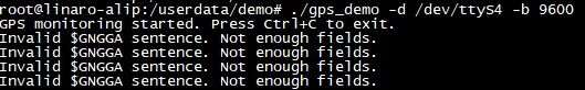
Press Ctrl+C to force quit the program
