WIFI
The development board uses the RTL8723DU module, and the WIFI part is already adapted by default.
Connect to WIFI
As shown in the figure, find the upper right corner of the system and click the network icon to connect to WIFI 
Use the ifconfig command to view IP address and other information
root@linaro-alip:/# ifconfig
···
wlx78228877b4a5: flags=4163<UP,BROADCAST,RUNNING,MULTICAST>  mtu 1500
        inet 192.168.137.149  netmask 255.255.255.0  broadcast 192.168.137.255
        inet6 fe80::d175:3cd1:73ca:ecc8  prefixlen 64  scopeid 0x20<link>
        ether 78:22:88:77:b4:a5  txqueuelen 1000  (Ethernet)
        RX packets 69  bytes 954099 (931.7 KiB)
        RX errors 0  dropped 143  overruns 0  frame 0
        TX packets 72  bytes 116372 (113.6 KiB)
        TX errors 0  dropped 23 overruns 0  carrier 0  collisions 0
Connectivity Test
Execute the following command to view the obtained IP address, and use the ping command to test whether the development board and PC can communicate normally. 192.168.49.85 is the actual IP address of the PC. Please make sure that the development board and PC are in the same LAN.
root@linaro-alip:/# ping 192.168.49.85 -I wlx78228877b4a5 -c 8
ping 192.168.49.85 -I wlx78228877b4a5 -c 8
PING 192.168.49.85 (192.168.49.85) from 192.168.137.149 wlx78228877b4a5: 56(84) bytes of data.
64 bytes from 192.168.49.85: icmp_seq=1 ttl=127 time=5.14 ms
64 bytes from 192.168.49.85: icmp_seq=2 ttl=127 time=3.66 ms
64 bytes from 192.168.49.85: icmp_seq=3 ttl=127 time=2.83 ms
64 bytes from 192.168.49.85: icmp_seq=4 ttl=127 time=2.81 ms
64 bytes from 192.168.49.85: icmp_seq=5 ttl=127 time=9.44 ms
64 bytes from 192.168.49.85: icmp_seq=6 ttl=127 time=2.77 ms
64 bytes from 192.168.49.85: icmp_seq=7 ttl=127 time=3.46 ms
64 bytes from 192.168.49.85: icmp_seq=8 ttl=127 time=3.09 ms

--- 192.168.49.85 ping statistics ---
8 packets transmitted, 8 received, 0% packet loss, time 7011ms
rtt min/avg/max/mdev = 2.771/4.150/9.442/2.128 ms
TCP Bandwidth Test
Use the iperf3 tool to test the network communication bandwidth between the development board and the PC as follows.
Server
Install the iperf3 tool on the development board and run the following command:
root@linaro-alip:/# sudo apt update
root@linaro-alip:/# sudo apt install iperf3
The development board acts as the server and executes the following commands:
root@linaro-alip:/# iperf3 -s
-----------------------------------------------------------
Server listening on 5201 (test #1)
-----------------------------------------------------------
Client
The iperf3 tool for Windows can be obtained in the test tool kit.
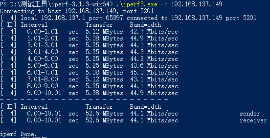
Open PowerShell in the Windows system, enter the path where the iperf3 tool is located, and use Windows as the client to send data. Execute the following command:
.\iperf3.exe -c 192.168.137.149 // 192.168.137.149为服务端IP地址Test Results
- Server
root@linaro-alip:/# iperf3 -s
-----------------------------------------------------------
Server listening on 5201 (test #1)
-----------------------------------------------------------
Accepted connection from 192.168.137.1, port 65396
[  5] local 192.168.137.149 port 5201 connected to 192.168.137.1 port 65397
[ ID] Interval           Transfer     Bitrate
[  5]   0.00-1.00   sec  4.88 MBytes  40.9 Mbits/sec
[  5]   1.00-2.00   sec  5.40 MBytes  45.3 Mbits/sec
[  5]   2.00-3.00   sec  5.22 MBytes  43.8 Mbits/sec
[  5]   3.00-4.00   sec  5.36 MBytes  45.0 Mbits/sec
[  5]   4.00-5.00   sec  5.14 MBytes  43.1 Mbits/sec
[  5]   5.00-6.00   sec  5.22 MBytes  43.8 Mbits/sec
[  5]   6.00-7.00   sec  5.40 MBytes  45.3 Mbits/sec
[  5]   7.00-8.00   sec  5.12 MBytes  43.0 Mbits/sec
[  5]   8.00-9.00   sec  5.38 MBytes  45.1 Mbits/sec
[  5]   9.00-10.00  sec  5.24 MBytes  43.9 Mbits/sec
[  5]  10.00-10.05  sec   266 KBytes  45.9 Mbits/sec
- - - - - - - - - - - - - - - - - - - - - - - - -
[ ID] Interval           Transfer     Bitrate
[  5]   0.00-10.05  sec  52.6 MBytes  43.9 Mbits/sec                  receiver
------------------------------------------------------------ Client