40pin IO Development
Experiment 07 - SPI Experiment
RDK X5 provides SPI1 bus on 40PIN physical pins 19, 21, 23, 24, 26, supports two chip selects, IO voltage 3.3V.
Loopback test: connect MISO and MOSI on the hardware, then run the SPI test program to write and read. The expected result is that the read data equals the written data.
Hardware Connection
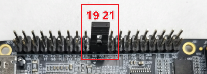
Connect MISO (IO19) and MOSI (IO21) directly with a jumper:
Software Operation
Enter the user home directory and run:
cd usersudo python3 ./test_spi.py
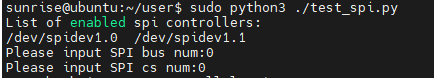
Select the bus number and chip select number from the printed SPI controllers. For example, test spidev0.0, then bus num and cs num are 0, press Enter to confirm:
Terminal as shown:
If the program runs correctly, it will keep printing 0x55 0xAA. If it prints 0x00 0x00, the SPI loopback test failed.
Terminal as shown:

#!/usr/bin/env python3

import sys
import signal
import os
import time

# Import spidev module
import spidev

def signal_handler(signal, frame):
    sys.exit(0)

def BytesToHex(Bytes):
    return ''.join(["0x%02X " % x for x in Bytes]).strip()

def spidevTest():
    # Set SPI bus (0, 1, 2) and chip select (0, 1)
    spi_bus = input("Please input SPI bus num:")
    spi_device = input("Please input SPI cs num:")
    # Create spidev object to access spidev-based Python functions
    spi=spidev.SpiDev()
    # Open SPI bus handle
    spi.open(int(spi_bus), int(spi_device))

    # Set SPI frequency to 12MHz
    spi.max_speed_hz = 12000000

    print("Starting demo now! Press CTRL+C to exit")

    # Send [0x55, 0xAA], received data should also be [0x55, 0xAA]
    try:
        while True:
            resp = spi.xfer2([0x55, 0xAA])
            print(BytesToHex(resp))
            time.sleep(1)

    except KeyboardInterrupt:
        spi.close()

if __name__ == '__main__':
    signal.signal(signal.SIGINT, signal_handler)
    print("List of enabled spi controllers:")
    os.system('ls /dev/spidev*')

    spidevTest()