RDK-S100 Hardware Introduction
Overview
RDK-S100 is a development board designed for machine vision and robotics applications, providing rich peripheral interfaces to meet development needs for cameras, sensors, displays, and communication scenarios. This document summarizes commonly used hardware interfaces and basic operation methods for quick setup and debugging.
Interface Overview
- RDK S100
- RDK S100 Module
RDK S100 provides Ethernet, USB, Camera, LCD, HDMI, CANFD, 40PIN and other functional interfaces, facilitating users in developing and testing image multimedia, deep learning algorithms, and other applications. The board interface layout is as follows:
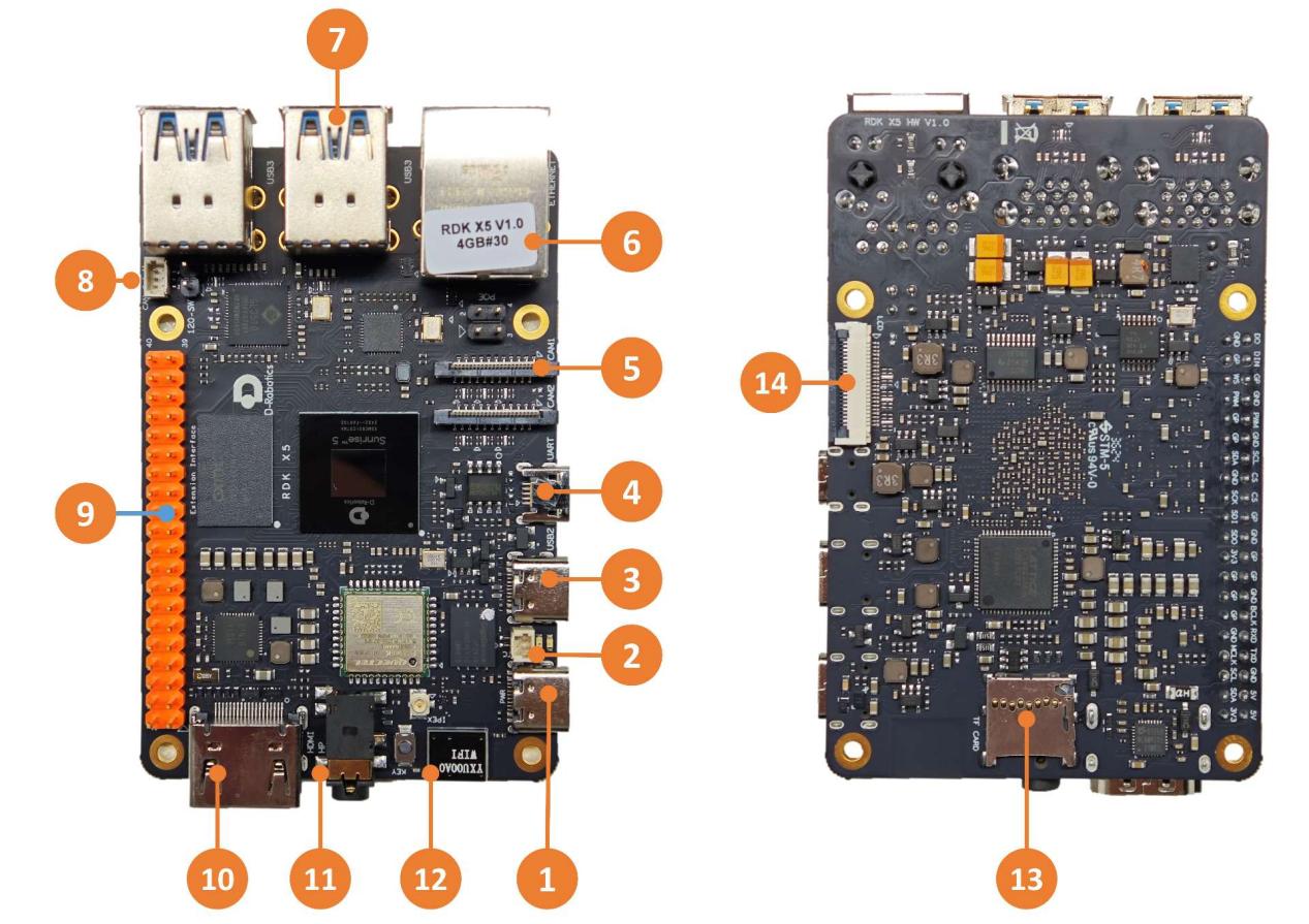
| No. | Function | No. | Function | No. | Function |
|---|---|---|---|---|---|
| 1 | Power Supply Interface (USB Type C) | 2 | RTC Battery Interface | 3 | Flash Connection Interface (USB Type C) |
| 4 | Debug Serial Port (Micro USB) | 5 | 2 MIPI Camera Interfaces | 6 | Gigabit Ethernet Port, PoE Supported |
| 7 | 4 USB 3.0 Type A Interfaces | 8 | CAN FD High-Speed Interface | 9 | 40PIN Interface |
| 10 | HDMI Display Interface | 11 | Multi-Standard Compatible Headphone Interface | 12 | Onboard Wi-Fi Antenna |
| 13 | TF Card Interface (Bottom) | 14 | LCD Display Interface (MIPI DSI) |
Warning
When the RTC is powered by a battery, the battery voltage and discharge current requirements are: 2~3.3V, >2.5uA. After power-on, when the PMIC detects that the RTC voltage is low enough for charging, it will automatically charge the RTC. Battery requirements are: maximum allowable charging voltage ≥3.3V, maximum allowable charging current >1mA.
Additionally, non-rechargeable RTC batteries cannot be used for power supply
Core Module Interface
- RDK S100
- RDK S100 Module
Full board-level design, no core module.
Power Supply Interface
- RDK S100
- RDK S100 Module
The development board provides one USB Type C interface (interface 1) as the power supply interface. A power adapter supporting 5V/5A is required to power the development board. After connecting the power adapter to the development board, the green power indicator light will illuminate, indicating normal power supply. After version 3.1.0, the orange status indicator light flashing indicates normal system operation.
Warning
Please do not use the computer USB interface to power the development board, as insufficient power supply may cause abnormal shutdowns, repeated restarts, and other issues.
Debug Serial Port
- RDK S100
- RDK S100 Module
The development board provides one debug serial port (interface 4) for serial login and debugging functions. The serial tool parameters on the computer should be configured as follows:
- Baud rate: 115200
- Data bits: 8
- Parity: None
- Stop bits: 1
- Flow Control: None
To connect via serial port, use a Micro-USB cable to connect interface 4 on the development board to the PC.
During the kernel boot phase, the baud rate configuration is located in the /boot/boot.cmd file;
After modifying the serial port configuration, you need to regenerate the boot.scr file with the following command: mkimage -C none -A arm -T script -d boot.cmd boot.scr.
Typically, users need to install the CH340 driver on the computer when using this interface for the first time. Users can search for "CH340 serial driver" to download and install.
Wired Ethernet Port
The development board provides one Gigabit Ethernet interface (interface 6), supporting 1000BASE-T and 100BASE-T standards. It uses static IP mode by default with IP address 192.168.127.10. To confirm the development board's IP address, you can log in via serial port and use the ifconfig command to view the eth0 network interface configuration.
Additionally, this interface supports PoE (Power over Ethernet) functionality, allowing data and power transmission through a single Ethernet cable without additional power cables, making device installation more convenient and flexible.
HDMI Display Interface
- RDK S100
- RDK S100 Module
The development board provides one HDMI (interface 10) display interface, supporting up to 1080P resolution. The development board outputs the Ubuntu system desktop via the HDMI interface (Ubuntu Server version displays logo icon). Additionally, the HDMI interface supports real-time display of camera and network stream video.
USB Interface
- RDK S100
- RDK S100 Module
The development board implements multi-channel USB interface expansion through hardware circuitry to meet users' needs for multi-channel USB device access. The interface descriptions are as follows:
| Interface Type | Interface No. | Quantity | Description |
|---|---|---|---|
| USB 2.0 Type C | Interface 3 | 1 channel | USB Device mode, used to connect to host for ADB, Fastboot, system flashing and other functions |
| USB 3.0 Type A | Interface 7 | 4 channels | USB Host mode, expanded through HUB to provide 4 USB ports for USB 3.0 peripherals |
Connecting USB Flash Drive
The development board's USB Type A interface supports USB flash drive functionality and can automatically detect USB flash drive insertion. The default mount directory is /media/soda1.
Connecting USB Serial Adapter Board
The development board's USB Type A interface supports USB serial adapter board functionality and can automatically detect USB serial adapter board insertion, creating device nodes /dev/ttyUSB* or /dev/ttyACM* (asterisk represents numbers starting from 0).
USB Camera
The development board's USB Type A interface supports USB camera functionality and can automatically detect USB camera insertion, creating device node /dev/video0.
MIPI Camera Interface
- RDK S100
- RDK S100 Module
The development board provides 2 channels of 22-pin MIPI CSI interfaces (interface 5), supporting connection of 2 MIPI cameras and dual-camera setups. Currently, the development board supports various camera module specifications. The module models and specifications are as follows:
| No. | Sensor | Resolution | FOV | I2C Device Address |
|---|---|---|---|---|
| 1 | IMX219 | 800W | ||
| 2 | OV5647 | 500W | ||
| 3 | IMX477 | 1230W |
The camera module connects to the development board via a 22-pin same-direction cable. The metal side of the cable should be inserted into the connector with the black buckle facing away.
After installation, users can use the i2cdetect command to confirm whether the module I2C address can be detected normally.
Query the I2C device address of the Camera Sensor on the mipi_host0 interface (near the Ethernet port):
echo 353 > /sys/class/gpio/export
echo out > /sys/class/gpio/gpio353/direction
echo 0 > /sys/class/gpio/gpio353/value
sleep 0.1
echo 1 > /sys/class/gpio/gpio353/value

i2cdetect -y -r 6
Query the I2C device address of the Camera Sensor on the mipi_host2 interface (far from the Ethernet port):
echo 351 > /sys/class/gpio/export
echo out > /sys/class/gpio/gpio351/direction
echo 0 > /sys/class/gpio/gpio351/value
sleep 0.1
echo 1 > /sys/class/gpio/gpio351/value

i2cdetect -y -r 4
When the Camera Sensor I2C device address is successfully detected, you can see the following print output (example: detecting IMX219 on interface mipi_host2, you can see address 10 is printed):
root@ubuntu:~# i2cdetect -y -r 4
0 1 2 3 4 5 6 7 8 9 a b c d e f
00: -- -- -- -- -- -- -- --
10: 10 -- -- -- -- -- -- -- -- -- -- -- -- -- -- --
20: -- -- -- -- -- -- -- -- -- -- -- -- -- -- -- --
30: -- -- -- -- -- -- -- -- -- -- -- -- -- -- -- --
40: -- -- -- -- -- -- -- -- -- -- -- -- -- -- -- --
50: -- -- -- -- -- -- -- -- -- -- -- -- -- -- -- --
60: -- -- -- -- -- -- -- -- -- -- -- -- -- -- -- --
70: -- -- -- -- -- -- -- --
Warning
Important: Do not hot-swap the camera while the development board is powered on, as this can easily damage the camera module.
LCD Display Interface
- RDK S100
- RDK S100 Module
RDK S100 provides one MIPI DSI LCD display interface (interface 14), which can be used for connecting LCD displays. The interface is 22-pin and can directly connect to various Raspberry Pi LCD displays using DSI-Cable-12cm cable.
Micro SD Interface
- RDK S100
- RDK S100 Module
The development board provides 1 Micro SD card slot (interface 13). It is recommended to use a storage card with at least 16GB capacity to meet the installation requirements of the Ubuntu operating system and related function packages.
Warning
Hot-swapping the TF storage card during development board operation is prohibited, as it may cause system operation abnormalities or even damage the storage card file system.
Wi-Fi Antenna Interface
- RDK S100
- RDK S100 Module
The development board's wireless network supports both onboard and external antenna configurations. Under normal circumstances, the onboard antenna can meet usage requirements. When the development board is installed in a metal casing, it is necessary to connect an external antenna to the antenna interface (next to interface 12) to enhance signal strength.
CANFD Interface
- RDK S100
- RDK S100 Module
RDK S100 development board provides CANFD interface (interface 8) and CAN terminal resistor access switch (2-pin header after interface 8). Terminal resistors must be enabled on both ends for high-speed communication to prevent signal reflection and improve anti-interference capability. It can be used for CAN and CAN FD communication. For more information, please refer to the CAN Usage chapter.
40PIN Interface
- RDK S100
- RDK S100 Module
RDK S100 development board provides a 40PIN interface with IO signals designed at 3.3V voltage level. The pin definitions are compatible with Raspberry Pi and other products. For detailed pin definitions and multiplexing relationships, refer to the hardware development chapter.
Connector Models
- RDK S100
- RDK S100 Module
| Connector | Model | Manufacturer | Description |
|---|---|---|---|
| J1 | HDGC1002WV-S-2P | HDGC (Huade Chuangchuang) | RTC Battery Interface |
| J14/J15 | AFC11-S22ICA-00 | JS (Jushuo Electronics) | MIPI Camera Interface |
| J16 | AFC01-S22FCA-00 | JS (Jushuo Electronics) | LCD Display Interface |
| J18 | HDGC1002WV-S-3P | HDGC (Huade Chuangchuang) | CAN FD High-Speed Interface |
Interface Power Load Capacity
The following data represents the load current capacity for a single interface. When multiple interfaces are used simultaneously, performance may be affected.
- RDK S100
- RDK S100 Module
| Interface | Load Capacity |
|---|---|
| CAN Interface | 500mA @ 3.3V |
| DSI Interface | 500mA @ 3.3V |
| 40Pin Interface | 1A @ 3.3V/1A @ 5V |
| USB3 Interface | 1A @ 5V |