02 Setting Up the Development Environment
At this stage, most OpenHarmony development boards do not support compiling source code in the Windows environment. For individual developers or student friends, they usually build a local Linux virtual machine such as Ubuntu through VMware for compilation. For company developers or experts with their own servers at home, they don't need a virtual machine environment, but the corresponding operations are exactly the same, just with different compilation speeds.
Using DevEco Device Tool essentially builds a Windows+Ubuntu hybrid development environment, where the Windows platform's DevEco Device Tool visual interface is used for related operations, and it connects remotely to the DevEco Device Tool under Ubuntu (Visual Studio Code may not need to be installed under Ubuntu). Then, operations such as development, compilation, and flashing of the source code under Ubuntu can be performed.
1 Downloading Development Tools
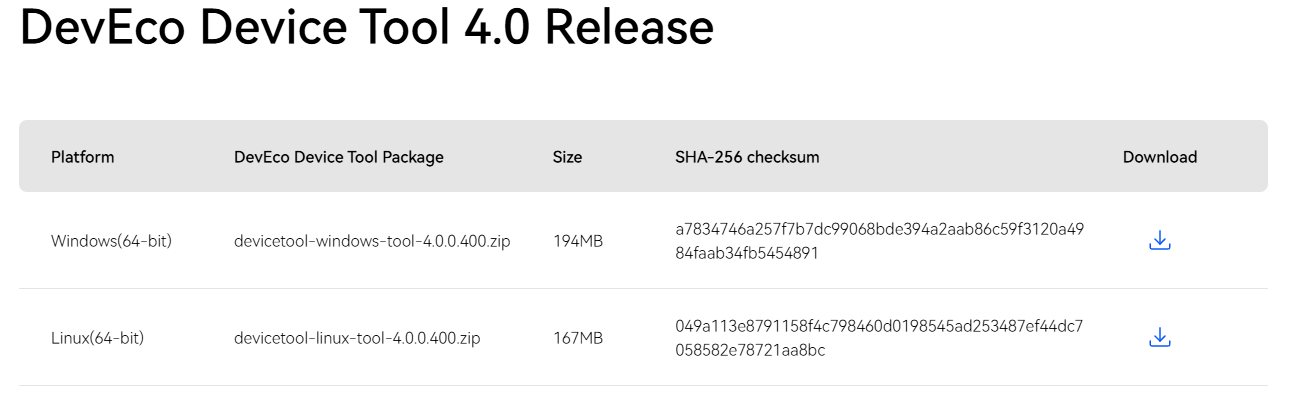
First, we download the DevEco Device Tool installation packages for Windows and Linux environments.
Download Address: Huawei Integrated Development Environment IDE DevEco Device Tool Download | HarmonyOS Device Development
2 Setting Up Linux Environment
Taking Ubuntu 20.04 version as an example.
(If the virtual machine has not been installed yet, please refer to the virtual machine installation tutorial: Ubuntu20.04 Installation Guide and Preliminary Environment Configuration (Super Detailed) includes [ROS Noetic, Terminator, Pycahrm and other common tools installation]_mt6701网卡 Ubuntu-CSDN Blog)
For file transfer between Linux and Windows, it is recommended to use the commonly used Mobextern free remote tool, which is very powerful. Since this article is mainly for setting up the environment for DevEco Device Tool, please refer to MobaXterm Detailed Usage Tutorial_mobaxterm Usage Tutorial-CSDN Blog for detailed usage.)
After configuring the virtual machine environment and being able to transfer files between Windows, perform the following operations:
2.1 Confirming Shell Environment
- Execute the following command to confirm the output is bash.
ls -l /bin/sh
If the output is not bash, please open the terminal tool, execute the following command, enter the password, and select No to change Ubuntu shell from dash to bash.
sudo dpkg-reconfigure dash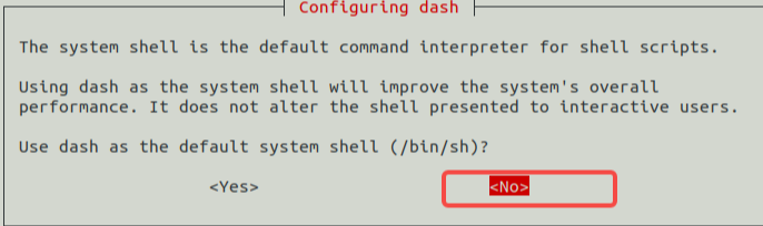
2.2 Installing DevEco Device Tool
- Place the devicetool-linux-tool-4.0.0.400.zip file in the directory under Linux where you store software tool packages, and use the extraction command:
unzip devicetool-linux-tool-{Version}.zip
# {Version} is the corresponding version number. For example, I enter: unzip devicetool-linux-tool-4.0.0.400.zip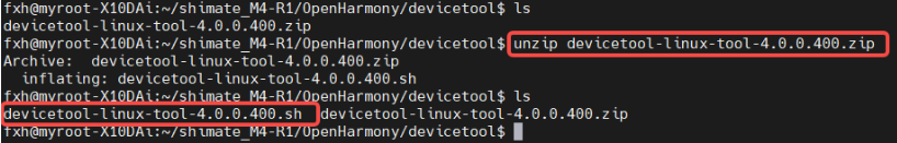
- Enter the extracted folder and execute the following command to give the installation file executable permissions. Please modify devicetool-linux-tool-{Version}.sh according to the actual situation.
chmod u+x devicetool-linux-tool-{Version}.sh- Execute the following command to install DevEco Device Tool. Please modify devicetool-linux-tool-{Version}.sh according to the actual situation.
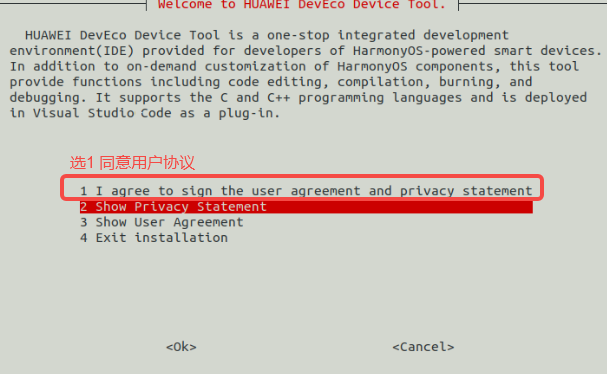
sudo ./devicetool-linux-tool-{Version}.sh- On the user agreement and privacy statement signing interface, please read the user agreement and privacy statement in detail. You must agree to the user agreement and privacy statement to proceed with the next step of installation. You can use the up and down arrow keys on the keyboard to make selections.
- When the interface outputs "DevEco Device Tool successfully installed.", it indicates that DevEco Device Tool is installed successfully.

3 Setting Up Windows Environment
Download the latest Windows version software package of DevEco Device Tool.
Extract the DevEco Device Tool compression package, double-click the installer program, and click Next to install.
Please read the user agreement and privacy statement. You must check "I accept the terms of the license agreement" before you can proceed to the next step of installation.
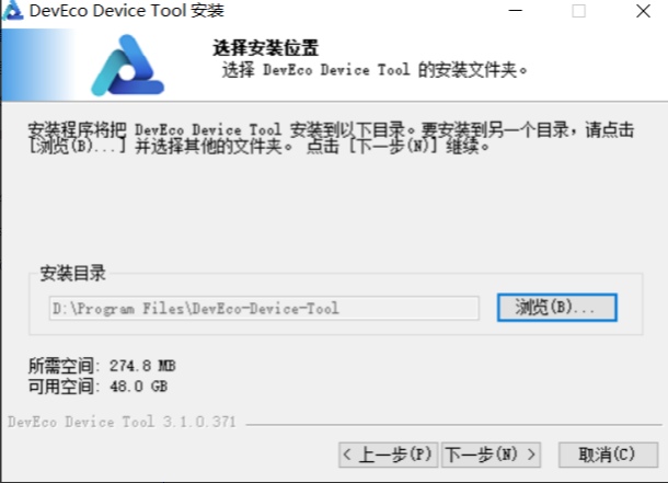
Set the installation path for DevEco Device Tool. Note that the installation path cannot contain Chinese characters. It is not recommended to install to the C drive directory. Click Next.
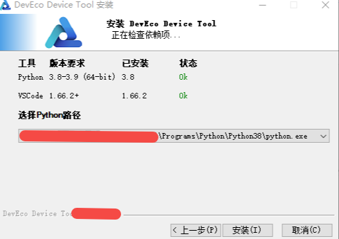
- According to the installation wizard prompts, install the dependent tools.
- Install: Install directly according to the default path and parameters.
- Custom Install: You can modify the installation path and other setting parameters before installation.
After the installation is completed, the status of each software displays as OK.
After the dependent tools are installed, click Install to start installing DevEco Device Tool.
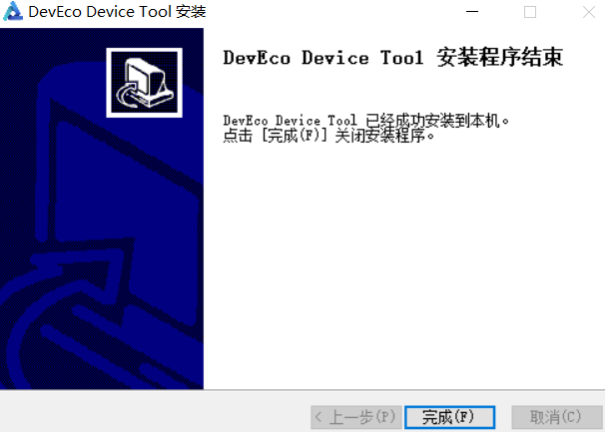
Continue waiting for the DevEco Device Tool installation wizard to automatically install the DevEco Device Tool plugin until the installation is complete. Click Finish to close the DevEco Device Tool installation wizard.
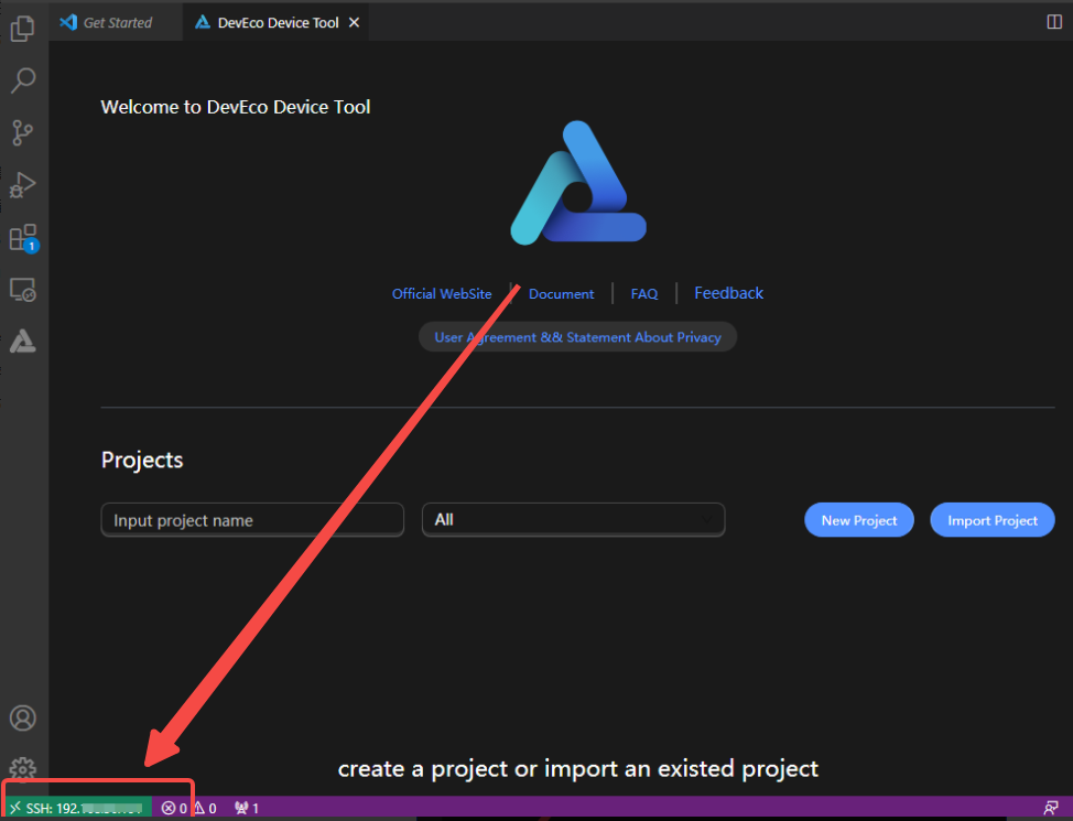
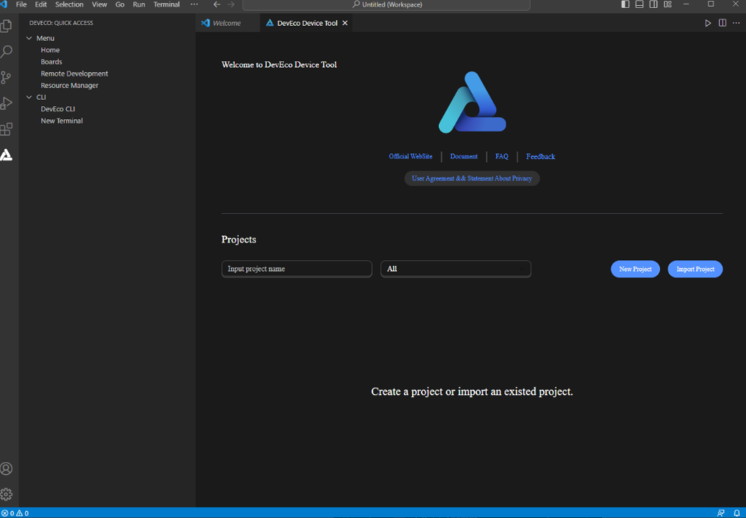
Open Visual Studio Code and enter the DevEco Device Tool tool interface. So far, the DevEco Device Tool Windows development environment installation is complete.
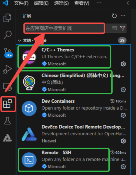
- After entering Visual Studio Code, click Extensions (or press Ctrl+Shift+X), search for the three marked plugins below, install them, and restart.
4 Configuring Windows Remote Access Ubuntu Environment
4.1 Installing SSH on Ubuntu and Getting IP Address
- In the Ubuntu system, open the terminal tool and execute the following commands to install and start the SSH service.
sudo apt-get install openssh-server
sudo systemctl start ssh- Execute the following command to get the current user's IP address for the Windows system to remotely access the Ubuntu environment.
ifconfig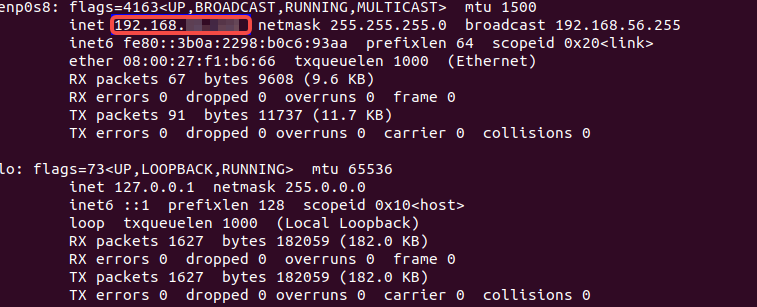
Note
If executing the ifconfig command prompts "command-not-found", please execute the sudo apt-get install net-tools command to install the network query tool, and then query the IP address again.
4.2 Remotely Connecting to Ubuntu
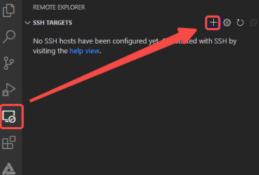
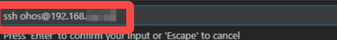
- Open Visual Studio Code on the Windows system, click the small TV icon on the left, and under SSH TARGETS, click +.
- In the pop-up SSH connection command input box, enter "ssh username@ip_address", where ip_address is the IP address of the remote computer to connect to, and username is the account to log in to the remote computer (for example, here it is ohos).
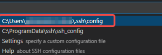
- In the pop-up input box, select the SSH configuration file. The default first option is fine.
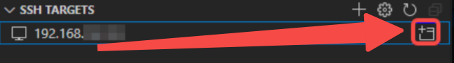
- In SSH TARGETS, find the remote computer and click the folder icon on the right to open the remote computer.
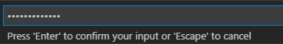
- On the first connection, in the pop-up input box, select Linux, then select Continue, and then enter the password to log in to the remote computer to connect to the remote computer.
So far, the environment setup is complete.