Raspberry Pi Expansion Board
1. Raspberry Pi RS485/CAN Expansion Board
M4-R1 does not support CAN communication. You can use this expansion board to expand one CAN interface through SPI communication.
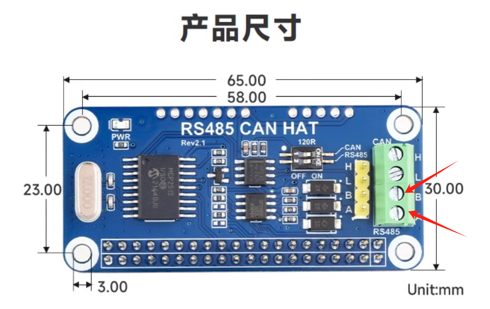
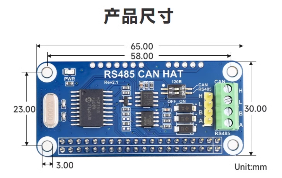
Expansion board physical diagram:
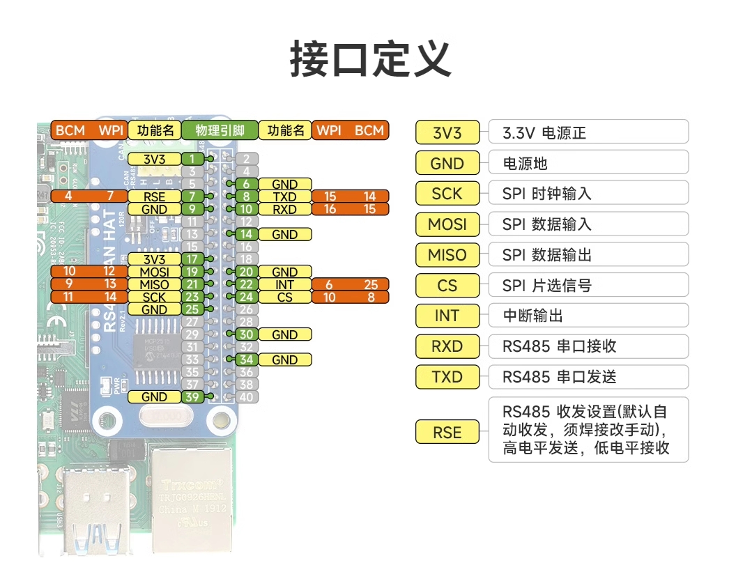
Expansion board pin comparison chart:
2. CAN Communication
2.1 DTS Configuration
This expansion board uses MCP2515 to implement CAN communication. The DTS configuration for MCP2515 is as follows:
Note
MCP2515 is not adapted in the firmware. If you need to use the CAN interface, configure it according to the following content.
- arch/arm64/boot/dts/rockchip/rk3568-toybrick-x0-linux.dts
    / {
        mcp251x_clk: mcp251x-clk {
                    compatible = "fixed-clock";
                    #clock-cells = <0>;
                    clock-frequency = <12000000>;       // Set according to MCP2515 module hardware crystal oscillator 12MHz
            };
    };

    &spi3{
    	status = "okay";
        pinctrl-0 = <&spi3m1_cs0 &spi3m1_pins>;
        pinctrl-1 = <&spi3m1_cs0 &spi3m1_pins_hs>;
        max-freq = <5000000>;
        mcp2515: mcp2515 {
            compatible = "microchip,mcp2515";
            pinctrl-names = "default";
            pinctrl-0 = <&mcp2515_irq1_pins>;
            reg = <0>;
            clocks = <&mcp251x_clk>;
            spi-max-frequency = <2000000>;
            interrupt-parent = <&gpio3>;
            interrupts = <RK_PB1 IRQ_TYPE_EDGE_FALLING>;
            vdd-supply = <&vcc3v3_sys>;
            xceiver-supply = <&vcc3v3_sys>;
            status = "okay";
        };
    };

    &pinctrl {
        mcp2515 {
            mcp2515_irq1_pins: mcp2515-irq1-pins {
                            rockchip,pins = <3 RK_PB1 RK_FUNC_GPIO &pcfg_pull_none>;
                    };
            };
    };
2.2 CAN Transceiver Testing
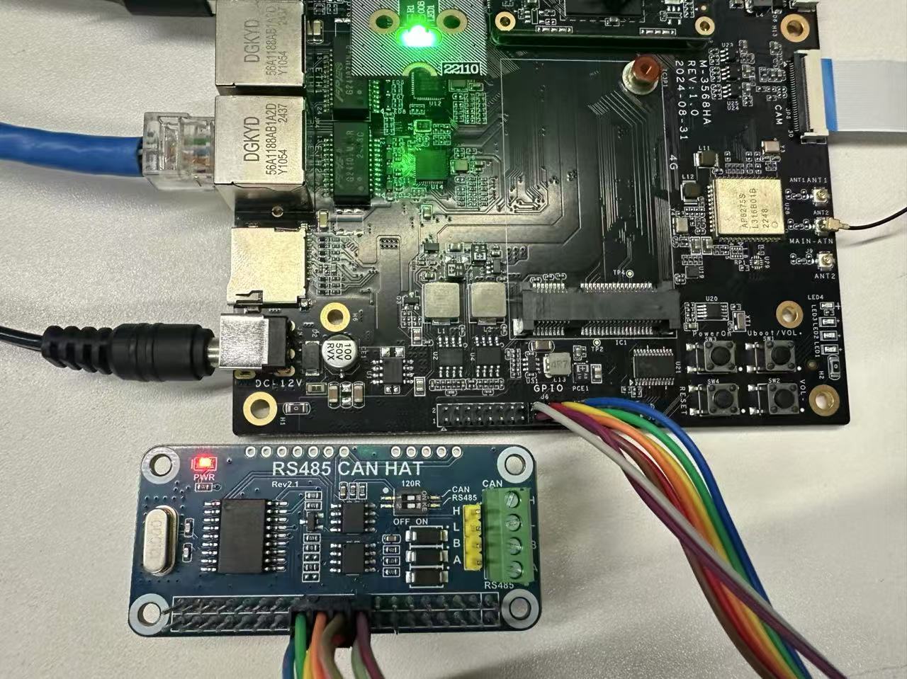
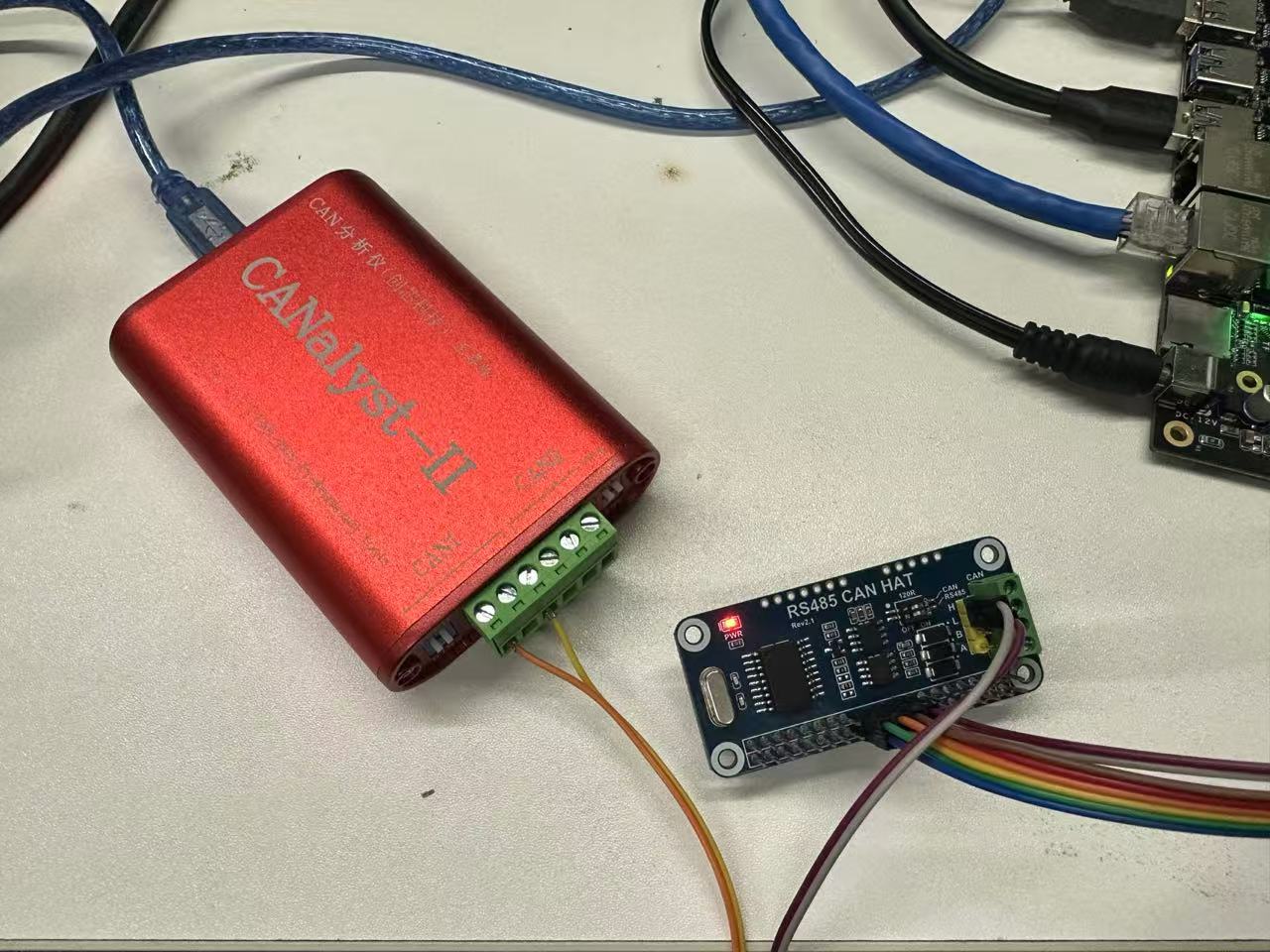
First, connect the expansion board to the M4-R1 board's 40PIN.
Connection as shown in the figure:
2.2.1 Loopback Test
The board has CAN testing tools. After connecting the expansion board, enter the command to test.
Note 1. Loopback test does not require connecting CAN_H and CAN_L; 2. Pin connection method is one-to-one correspondence, i.e., pin 1 corresponds to expansion board pin 1;
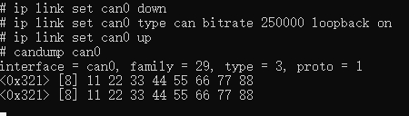
Set baud rate and loopback mode:
    # Close CAN0 interface
    ip link set can0 down
    # Set bit rate to 250000Hz, and enable loopback mode
    ip link set can0 type can bitrate 250000 loopback on
    # Enable CAN0 interface
    ip link set can0 up
Open two terminal windows to test can0 self-transmit and receive:
    # Terminal 1
    candump can0

    # Terminal 2
    cansend can0 -i 0x321 0x11 0x22 0x33 0x44 0x55 0x66 0x77 0x88

    # Or use just one terminal
    candump can0 &
    cansend can0 -i 0x321 0x11 0x22 0x33 0x44 0x55 0x66 0x77 0x88
Test effect is as follows:
- Terminal 1:
- Terminal 2:

2.2.2 Communication Test with CAN Analyzer
Connect the expansion board and analyzer.
| Expansion Board | CAN Analyzer |
|---|---|
| CAN_H | CAN_H |
| CAN_L | CAN_L |
Set baud rate and test.
# Close CAN0 interface
sudo ip link set can0 down
# Set bit rate to 250000
sudo ip link set can0 type can bitrate 250000
# Enable CAN0 interface
sudo ip link set can0 up
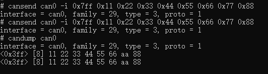
# Send (standard frame, data frame, ID:7ff, date:11223344556677)
cansend can0 -i 0x7ff 0x11 0x22 0x33 0x44 0x55 0x66 0x77 0x88
# Receive
candump can0- Terminal test effect:
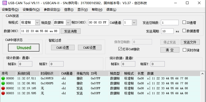
- CAN analyzer test effect:
3. RS485
This expansion board's 485 supports automatic switching of transmit/receive state, no program control needed. Just connect the expansion board's pins 8 and 10 to M4-R1's 40PIN pins 8 and 10, then connect 485 devices to the expansion board's A and B for transmission and reception.