HOME
Shop
  • English
  • 简体中文
HOME
Shop
  • English
  • 简体中文
  • Product Series

    • FPGA+ARM

      • GM-3568JHF

        • 1. Introduction

          • About GM-3568JHF
        • 2. Quick Start

          • 00 Introduction
          • 01 Environment Setup
          • 02 Compilation Instructions
          • 03 Flashing Guide
          • 04 Debug Tools
          • 05 Software Update
          • 06 View Information
          • 07 Test Commands
          • 08 App Compilation
          • 09 Source Code Acquisition
        • 3. Peripherals and Interfaces

          • 01 USB
          • 02 Display and Touch
          • 03 Ethernet
          • 04 WIFI
          • 05 Bluetooth
          • 06 TF-Card
          • 07 Audio
          • 08 Serial Port
          • 09 CAN
          • 10 RTC
        • 4. Application Development

          • 01 UART read and write case
          • 02 Key detection case
          • 03 LED light flashing case
          • 04 MIPI screen detection case
          • 05 Read USB device information example
          • 06 FAN Detection Case
          • 07 FPGA FSPI Communication Case
          • 08 FPGA DMA read and write case
          • 09 GPS debugging case
          • 10 Ethernet Test Cases
          • 11 RS485 reading and writing examples
          • 12 FPGA IIC read and write examples
          • 13 PN532 NFC card reader case
          • 14 TF card reading and writing case
        • 5. QT Development

          • 01 ARM64 cross compiler environment construction
          • 02 QT program added automatic startup service
        • 6. RKNN_NPU Development

          • 01 RK3568 NPU Overview
          • 02 Development Environment Setup
          • Run Official YOLOv5 Example
          • Model Conversion Detailed Explanation
          • Run Custom Model on Board
        • 7. FPGA Development

          • ARM and FPGA Communication
          • /fpga-arm/GM-3568JHF/FPGA/ch02-FPGA-Development-Manual.html
        • 8. Others

          • 01 Modification of the root directory file system
          • 02 System auto-start service
        • 9. Download

          • Download Resources
    • ShimetaPi

      • M4-R1

        • 1. Introduction

          • 1.1 About M4-R1
        • 2. Quick Start

          • 2.1 OpenHarmony Overview
          • 2.2 Image Burning
          • 2.3 Development Environment Preparation
          • 2.4 Hello World Application
        • 3. Application Development

          • 3.1 Getting Started

            • 3.1.1 ArkTS Language Overview
            • 3.1.2 UI Components (Part 1)
            • 3.1.3 UI Components (Part 2)
            • 3.1.4 UI Components (Part 3)
          • 3.2 Advanced

            • 3.2.1 Getting Started Guide
            • 3.2.2 Usage of Third Party Libraries
            • 3.2.3 Deployment of the Application
            • 3.2.4 Factory Reset
            • 3.2.5 System Debug
            • 3.2.6 APP Stability Testing
            • 3.2.7 Application Testing
          • 3.3 Getting Docs

            • 3.3.1 Official Website Information
          • 3.4 Development Instructions

            • 3.4.1 Full SDK
            • 3.4.2 Introduction of Third Party Libraries
            • 3.4.3 Introduction of HDC Tool
            • 3.4.4 Restore Factory Mode
            • 3.4.5 Update System API
          • 3.5 First Application

            • 3.5.1 First ArkTS App
          • 3.6 Application Demo

            • 3.6.1 UART Tool
            • 3.6.2 Graphics Tablet
            • 3.6.3 Digital Clock
            • 3.6.4 WIFI Tool
        • 4. Device Development

          • 4.1 Ubuntu Environment Development

            • 4.1.1 Environment Setup
            • 4.1.2 Download Source Code
            • 4.1.3 Compile Source Code
          • 4.2 Using DevEco Device Tool

            • 4.2.1 Tool Introduction
            • 4.2.2 Environment Construction
            • 4.2.3 Import SDK
            • 4.2.4 Function Introduction
        • 5. Peripherals and Interfaces

          • 5.1 Raspberry Pi Interfaces
          • 5.2 GPIO Interface
          • 5.3 I2C Interface
          • 5.4 SPI Communication
          • 5.5 PWM Control
          • 5.6 Serial Port Communication
          • 5.7 TF Card Slot
          • 5.8 Display Screen
          • 5.9 Touch Screen
          • 5.10 Audio
          • 5.11 RTC
          • 5.12 Ethernet
          • 5.13 M.2
          • 5.14 MINI PCIE
          • 5.15 Camera
          • 5.16 WIFI BT
          • 5.17 HAT
        • 6. FAQ

          • 6.1 Download Link
      • M5-R1

        • 1. Introduction

          • M5-R1 Development Documentation
        • 2. Quick Start

          • OpenHarmony Overview
          • Image Burning
          • Development Environment Preparation
          • Hello World Application and Deployment
        • 3. Peripherals and Interfaces

          • 3.1 Raspberry Pi Interfaces
          • 3.2 GPIO Interface
          • 3.3 I2C Interface
          • 3.4 SPI Communication
          • 3.5 PWM Control
          • 3.6 Serial Port Communication
          • 3.7 TF Card Slot
          • 3.8 Display Screen
          • 3.9 Touch Screen
          • 3.10 Audio
          • 3.11 RTC
          • 3.12 Ethernet
          • 3.13 M.2
          • 3.14 MINI PCIE
          • 3.15 Camera
          • 3.16 WIFI BT
          • 3.17 HAT
        • 4. Application Development

          • 4.1 Getting Started

            • 4.1.1 ArkTS Language Overview
            • 4.1.2 UI Components (Part 1)
            • 4.1.3 UI Components (Part 2)
            • 4.1.4 UI Components (Part 3)
          • 4.2 Advanced

            • 4.2.1 Getting Started Guide
            • 4.2.2 Usage of Third Party Libraries
            • 4.2.3 Deployment of the Application
            • 4.2.4 Factory Reset
            • 4.2.5 System Debug
            • 4.2.6 APP Stability Testing
            • 4.2.7 Application Testing
        • 5. Device Development

          • 5.1 Environment Setup
          • 5.2 Download Source Code
          • 5.3 Compile Source Code
        • 6. Download

          • Data Download
    • OpenHarmony

      • SC-3568HA

        • 1. Introduction

          • 1.1 About SC-3568HA
        • 2. Quick Start

          • 2.1 OpenHarmony Overview
          • 2.2 Image Burning
          • 2.3 Development Environment Preparation
          • 2.4 Hello World Application
        • 3. Application Development

          • 3.1 ArkUI

            • 3.1.1 ArkTS Language Overview
            • 3.1.2 UI Components (Part 1)
            • 3.1.3 UI Components (Part 2)
            • 3.1.4 UI Components (Part 3)
          • 3.2 Advanced

            • 3.2.1 Getting Started Guide
            • 3.2.2 Usage of Third Party Libraries
            • 3.2.3 Deployment of the Application
            • 3.2.4 Factory Reset
            • 3.2.5 System Debug
            • 3.2.6 APP Stability Testing
            • 3.2.7 Application Testing
        • 4. Device Development

          • 4.1 Environment Setup
          • 4.2 Download Source Code
          • 4.3 Compile Source Code
        • 5. Peripherals and Interfaces

          • 5.1 Raspberry Pi Interfaces
          • 5.2 GPIO Interface
          • 5.3 I2C Interface
          • 5.4 SPI Communication
          • 5.5 PWM Control
          • 5.6 Serial Port Communication
          • 5.7 TF Card Slot
          • 5.8 Display Screen
          • 5.9 Touch Screen
          • 5.10 Audio
          • 5.11 RTC
          • 5.12 Ethernet
          • 5.13 M.2
          • 5.14 MINI PCIE
          • 5.15 Camera
          • 5.16 WIFI BT
          • 5.17 HAT
        • 6. FAQ

          • 6.1 Download Link
      • M-K1HSE

        • 1. Introduction

          • 1.1 Product Introduction
        • 2. Quick Start

          • 2.1 Debug Tool Installation
          • 2.2 Development Environment Setup
          • 2.3 Source Code Download
          • 2.4 Build Instructions
          • 2.5 Flashing Guide
          • 2.6 APT Update Sources
          • 2.7 View Board Info
          • 2.8 CLI LED and Key Test
          • 2.9 GCC Build Programs
        • 3. Application Development

          • 3.1 Basic Application Development

            • 3.1.1 Development Environment Preparation
            • 3.1.2 First Application HelloWorld
            • 3.1.3 Develop HAR Package
          • 3.2 Peripheral Application Cases

            • 3.2.1 UART Read/Write
            • 3.2.2 Key Demo
            • 3.2.3 LED Flash
        • 4. Peripherals and Interfaces

          • 4.1 Standard Peripherals

            • 4.1.1 USB
            • 4.1.2 Display and Touch
            • 4.1.3 Ethernet
            • 4.1.4 WIFI
            • 4.1.5 Bluetooth
            • 4.1.6 TF Card
            • 4.1.7 Audio
            • 4.1.8 Serial Port
            • 4.1.9 CAN
            • 4.1.10 RTC
          • 4.2 Interfaces

            • 4.2.1 Audio
            • 4.2.2 RS485
            • 4.2.3 Display
            • 4.2.4 Touch
        • 5. System Customization Development

          • 5.1 System Porting
          • 5.2 System Customization
          • 5.3 Driver Development
          • 5.4 System Debugging
          • 5.5 OTA Upgrade
        • 6. Download

          • 6.1 Download
    • EVS-Camera

      • CF-NRS1

        • 1. Introduction

          • 1.1 About CF-NRS1
          • 1.2 Event-Based Concepts
          • 1.3 Quick Start
          • 1.4 Resources
        • 2. Development

          • 2.1 Development Overview

            • 2.1.1 Shimetapi Hybrid Camera SDK Introduction
          • 2.2 Environment & API

            • 2.2.1 Environment Overview
            • 2.2.2 Development API Overview
          • 2.3 Linux Development

            • 2.3.1 Linux SDK Introduction
            • 2.3.2 Linux SDK API
            • 2.3.3 Linux Algorithm
            • 2.3.4 Linux Algorithm API
          • 2.4 Service & Web

            • 2.4.1 EVS Server
            • 2.4.2 Time Server
            • 2.4.3 EVS Web
        • 3. Download

          • 3.1 Download
        • 4. Common Problems

          • 4.1 Common Problems
      • CF-CRA2

        • 1. Introduction

          • 1.1 About CF-CRA2
        • 2. Download

          • 2.1 Download
      • EVS Module

        • 1. Related Concepts
        • 2. Hardware Preparation and Environment Configuration
        • 3. Example Program User Guide
        • Resources Download
    • AI-model

      • 1684XB-32T

        • 1. Introduction

          • AIBOX-1684XB-32 Introduction
        • 2. Quick Start

          • First time use
          • Network Configuration
          • Disk usage
          • Memory allocation
          • Fan Strategy
          • Firmware Upgrade
          • Cross-Compilation
          • Model Quantization
        • 3. Application Development

          • 3.1 Development Introduction

            • Sophgo SDK Development
            • SOPHON-DEMO Introduction
          • 3.2 Large Language Models

            • Deploying Llama3 Example
            • /ai-model/AIBOX-1684XB-32/application-development/LLM/Sophon_LLM_api_server-Development-AIBOX-1684XB-32.html
            • /ai-model/AIBOX-1684XB-32/application-development/LLM/MiniCPM-V-2_6-AIBOX-1684XB-32.html
            • /ai-model/AIBOX-1684XB-32/application-development/LLM/Qwen-2-5-VL-demo-Development-AIBOX-1684XB-32.html
            • /ai-model/AIBOX-1684XB-32/application-development/LLM/Qwen-3-chat-demo-Development-AIBOX-1684XB-32.html
            • /ai-model/AIBOX-1684XB-32/application-development/LLM/Qwen3-Qwen Agent-MCP.html
            • /ai-model/AIBOX-1684XB-32/application-development/LLM/Qwen3-langchain-AI Agent.html
          • 3.3 Deep Learning

            • ResNet (Image Classification)
            • LPRNet (License Plate Recognition)
            • SAM (Universal Image Segmentation Foundation Model)
            • YOLOv5 (Object Detection)
            • OpenPose (Human Keypoint Detection)
            • PP-OCR (Optical Character Recognition)
        • 4. Download

          • Resource Download
      • 1684X-416T

        • 1. Introduction

          • AIBOX-1684X-416 Introduction
        • 2. Demo Simple Operation Guide

          • Simple instructions for using shimeta smart monitoring demo
      • RDK-X5

        • 1. Introduction

          • RDK-X5 Hardware Introduction
        • 2. Quick Start

          • RDK-X5 Quick Start
        • 3. Application Development

          • 3.1 AI Online Model Development

            • AI Online Development - Experiment01
            • AI Online Development - Experiment02
            • AI Online Development - Experiment03
            • AI Online Development - Experiment04
            • AI Online Development - Experiment05
            • AI Online Development - Experiment06
          • 3.2 Large Language Models (Voice)

            • Voice LLM Application - Experiment01
            • Voice LLM Application - Experiment02
            • Voice LLM Application - Experiment03
            • Voice LLM Application - Experiment04
            • Voice LLM Application - Experiment05
            • Voice LLM Application - Experiment06
          • 3.3 40pin-IO Development

            • 40pin IO Development - Experiment01
            • 40pin IO Development - Experiment02
            • 40pin IO Development - Experiment03
            • 40pin IO Development - Experiment04
            • 40pin IO Development - Experiment05
            • 40pin IO Development - Experiment06
            • 40pin IO Development - Experiment07
          • 3.4 USB Module Development

            • USB Module Usage - Experiment01
            • USB Module Usage - Experiment02
          • 3.5 Machine Vision

            • Machine Vision Technology Development - Experiment01
            • Machine Vision Technology Development - Experiment02
            • Machine Vision Technology Development - Experiment03
            • Machine Vision Technology Development - Experiment04
          • 3.6 ROS2 Base Development

            • ROS2 Basic Development - Experiment01
            • ROS2 Basic Development - Experiment02
            • ROS2 Basic Development - Experiment03
            • ROS2 Basic Development - Experiment04
      • RDK-S100

        • 1. Introduction

          • 1.1 About RDK-S100
        • 2. Quick Start

          • 2.1 First Use
        • 3. Application Development

          • 3.1 AI Online Model Development

            • 3.1.1 Volcano Engine Doubao AI
            • 3.1.2 Image Analysis
            • 3.1.3 Multimodal Visual Analysis
            • 3.1.4 Multimodal Image Comparison
            • 3.1.5 Multimodal Document Analysis
            • 3.1.6 Camera AI Vision Analysis
          • 3.2 Large Language Models

            • 3.2.1 Speech Recognition
            • 3.2.2 Voice Conversation
            • 3.2.3 Multimodal Image Analysis
            • 3.2.4 Multimodal Image Comparison
            • 3.2.5 Multimodal Document Analysis
            • 3.2.6 Multimodal Vision Application
          • 3.3 40pin-IO Development

            • 3.3.1 GPIO Output LED Blink
            • 3.3.2 GPIO Input
            • 3.3.3 Key Control LED
            • 3.3.4 PWM Output
            • 3.3.5 Serial Output
            • 3.3.6 I2C Experiment
          • 3.4 USB Module Development

            • 3.4.1 USB Voice Module
            • 3.4.2 Sound Source Localization
          • 3.5 Machine Vision

            • 3.5.1 USB Camera
            • 3.5.2 Image Processing Basics
            • 3.5.3 Object Detection
            • 3.5.4 Image Segmentation
          • 3.6 ROS2 Base Development

            • 3.6.1 Environment Setup
            • 3.6.2 Create and Build Workspace
            • 3.6.3 ROS2 Topic Communication
            • 3.6.4 ROS2 Camera Application
    • Core-Board

      • C-3568BQ

        • 1. Introduction

          • C-3568BQ Introduction
      • C-3588LQ

        • 1. Introduction

          • C-3588LQ Introduction
      • GC-3568JBAF

        • 1. Introduction

          • GC-3568JBAF Introduction
      • C-K1BA

        • 1. Introduction

          • C-K1BA Introduction

Model Quantization

Introduction

TPU-MLIR is the compiler project for Sophgo's deep learning processors. This project provides a complete toolchain that can convert pre-trained neural networks from different frameworks into bmodel files that can run efficiently on Sophgo's intelligent vision deep learning processors. The code has been open-sourced on github: https://github.com/sophgo/tpu-mlir .

The paper https://arxiv.org/abs/2210.15016 describes the overall design approach of TPU-MLIR.

The overall architecture of TPU-MLIR is as follows:

_images/framework.png

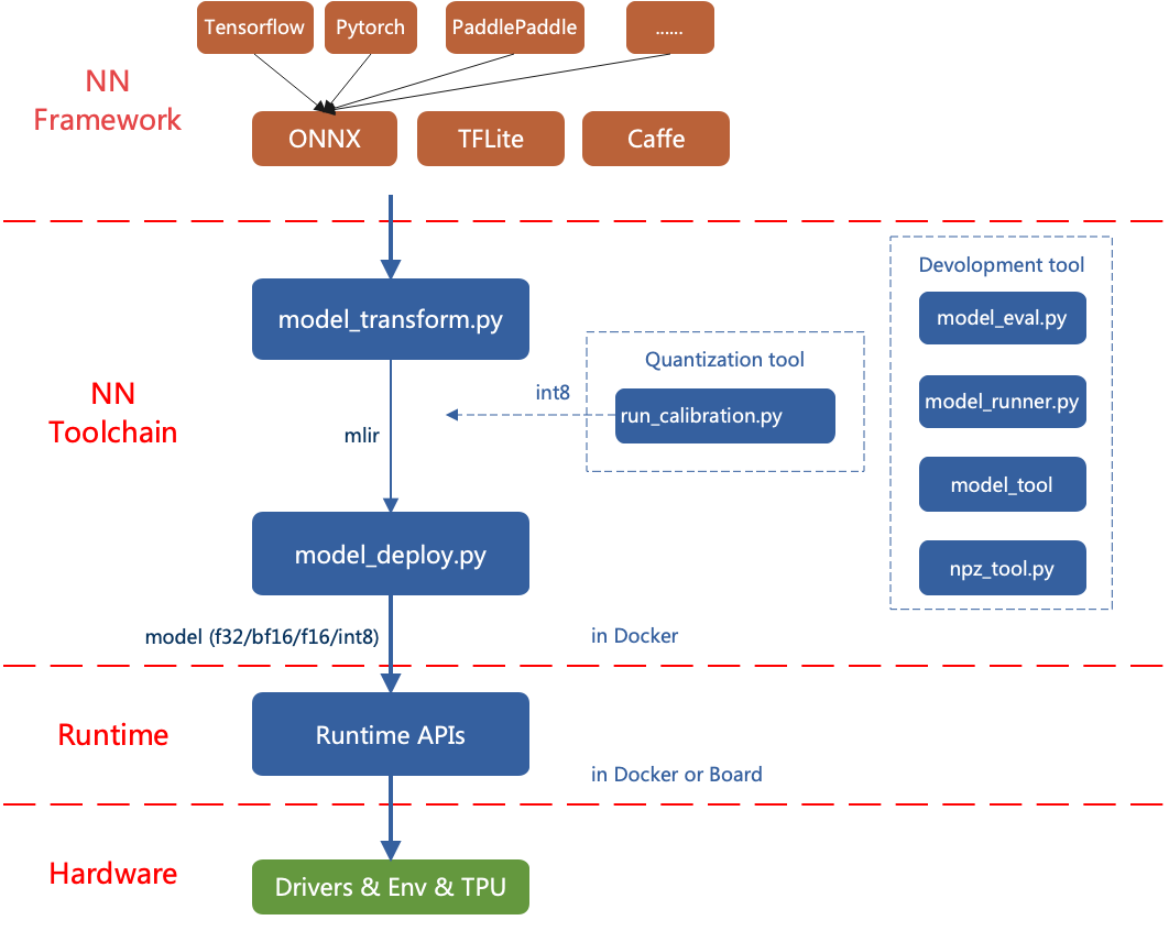
Currently, the directly supported frameworks are ONNX, Pytorch, Caffe, and TFLite. Models from other frameworks need to be converted to onnx format. For information on how to convert deep learning framework network models to onnx, please refer to the onnx official website: https://github.com/onnx/tutorials .

Model conversion needs to be executed in a specified docker. It mainly involves two steps: first, use model_transform.py to convert the original model to an mlir file, and second, use model_deploy.py to convert the mlir file to a bmodel.

If you want to convert an INT8 model, you need to call run_calibration.py to generate a calibration table and then pass it to model_deploy.py.

If the INT8 model does not meet the accuracy requirements, you can call run_qtable.py to generate a quantization table to determine which layers use floating-point calculation, and then pass it to model_deploy.py to generate a mixed-precision model.

1. Setting Up TPU-MLIR Environment

1.1 Basic Environment

To reduce storage pressure on the board side, use a non-BM1684X Linux system (using WSL as an example here) for model quantization and conversion; if your environment meets python >= 3.10 and ubuntu:22.04, you can skip the docker environment setup (this section).

Since the model conversion and quantization process can be affected by the libc version, the official image is used for environment setup. TPU-MLIR is developed in a Docker environment, and you can compile and run after configuring Docker.

If you are using Docker for the first time, execute the following commands to install and configure it (this operation is only required for the first time):

sudo apt install docker.io
sudo systemctl start docker
sudo systemctl enable docker
sudo groupadd docker
sudo usermod -aG docker $USER
newgrp docker

Pull the required image from dockerhub

docker pull sophgo/tpuc_dev:latest

If pulling fails, you can use wget to download the image directly to local

#Use wget to download the required image
wget https://sophon-assets.sophon.cn/sophon-prod-s3/drive/25/04/15/16/tpuc_dev_v3.4.tar.gz
#Load the image
docker load -i tpuc_dev_v3.4.tar.gz

Start the image environment

#First time creating the tpumlir environment, use the following command, --name tpumlir can be customized
docker run --privileged --name tpumlir -v $PWD:/workspace -it sophgo/tpuc_dev:latest
#If not the first time, just use the following command
docker run -v $PWD:/workspace -it sophgo/tpuc_dev:latest

1.2 Installing TPU-MLIR

TPU-MLIR provides three installation methods:

(1) Download and install directly from pypi (recommended):

pip install tpu_mlir -i https://pypi.tuna.tsinghua.edu.cn/simple

(2) Download the latest tpu_mlir-*-py3-none-any.whl from TPU-MLIR Github, then install using pip:

pip install tpu_mlir-*-py3-none-any.whl

Tips

TPU-MLIR requires different dependencies for processing models from different frameworks. For models generated from onnx or torch, install additional dependency environments using the following commands:

pip install tpu_mlir[onnx] -i https://pypi.tuna.tsinghua.edu.cn/simple
pip install tpu_mlir[torch] -i https://pypi.tuna.tsinghua.edu.cn/simple

Currently, five configurations are supported: onnx, torch, tensorflow, caffe, paddle. You can use one command to install multiple configurations, or install all dependency environments directly:

pip install tpu_mlir[onnx,torch,caffe] -i https://pypi.tuna.tsinghua.edu.cn/simple
pip install tpu_mlir[all] -i https://pypi.tuna.tsinghua.edu.cn/simple

(3) If you obtained a release package in the format tpu-mlir_${version}-${hash}-${date}.tar.gz, you can find this package by downloading sophon-SDK and checking the subdirectory (generally in the SDK-23.09-LTS-SP4\tpu-mlir_20231116_054500 directory). You can configure it this way:

#You can choose to download the SDK using the following command
wget https://sophon-assets.sophon.cn/sophon-prod-s3/drive/24/12/31/10/SDK-23.09-LTS-SP4.zip
#If you have previously installed mlir via pip, you need to uninstall it
pip uninstall tpu_mlir
#Extract and install the release package
tar xvf tpu-mlir_${version}-${hash}-${date}.tar.gz
cd tpu-mlir_${version}-${hash}-${date}
source envsetup.sh #Configure environment variables

It is recommended to use the TPU-MLIR image only for compiling and quantizing models, and program compilation and execution should be done in the development and runtime environment. For more TPU-MLIR tutorials, refer to the related webpage.

2. Compiling Models

This section uses yolov5s.onnx as an example to introduce how to compile and migrate an onnx model to run on the BM1684X platform. For other models, refer to the related examples.

2.1 Setting Up the Project Directory

Please download tpu-mlir-resource.tar from Assets on Github and extract it. After extraction, rename the folder to tpu_mlir_resource:

#You can download manually, or use wget to download as recommended
wget https://github.com/sophgo/tpu-mlir/releases/download/v1.20/tpu-mlir-resource.tar
#Extract the project directory
tar -xvf tpu-mlir-resource.tar
#Modify the file name
mv regression/ tpu_mlir-resource/

Tips

tpu-mlir-resource.tar is a sample resource file. If you want to convert your own model, this file is not required. Related configurations can be found in the Development Manual.

Create a model_yolov5s_onnx directory and put both the model file and image file into it:

mkdir model_yolov5s_onnx && cd model_yolov5s_onnx
wget https://github.com/ultralytics/yolov5/releases/download/v6.0/yolov5s.onnx
cp -rf tpu_mlir_resource/dataset/COCO2017 .
cp -rf tpu_mlir_resource/image .
mkdir workspace && cd workspace

2.2 Converting ONNX to MLIR

If the model uses image input, we need to understand the model's preprocessing before converting the model. If the model uses preprocessed npz files as input, preprocessing does not need to be considered.

The preprocessing process is expressed by the formula below (x represents the input):

$$ y=(x-mean)*scale $$

The official yolov5 images are in rgb format, each value is multiplied by 1/255, converted to mean and scale as 0.0,0.0,0.0 and 0.0039216,0.0039216,0.0039216.

The model conversion command is as follows:

$ model_transform \
    --model_name yolov5s \
    --model_def ../yolov5s.onnx \
    --input_shapes [[1,3,640,640]] \
    --mean 0.0,0.0,0.0 \
    --scale 0.0039216,0.0039216,0.0039216 \
    --keep_aspect_ratio \
    --pixel_format rgb \
    --output_names 350,498,646 \
    --test_input ../image/dog.jpg \
    --test_result yolov5s_top_outputs.npz \
    --mlir yolov5s.mlir

The main parameters of model_transform are as follows (for complete introduction, see the TPU-MLIR Development Reference Manual User Interface chapter):

Parameter NameRequiredDescription
model_nameYesSpecify the model name
model_defYesSpecify the model definition file, such as .onnx or .tflite or .prototxt file
input_shapesNoSpecify the input shape, for example [[1,3,640,640]]; a two-dimensional array, can support multiple inputs
input_typesNoSpecify the input type, for example int32; multiple inputs are separated by commas; defaults to float32 if not specified
resize_dimsNoThe size to resize the original image to; if not specified, resize to the model's input size
keep_aspect_ratioNoWhether to maintain aspect ratio during resize, defaults to false; if set, padding with 0 will be applied to insufficient parts
meanNoThe mean value of each channel of the image, defaults to 0.0,0.0,0.0
scaleNoThe scale value of each channel of the image, defaults to 1.0,1.0,1.0
pixel_formatNoImage type, can be rgb, bgr, gray, rgbd, defaults to bgr
channel_formatNoChannel type, for image input can be nhwc or nchw, for non-image input is none, defaults to nchw
output_namesNoSpecify the output names; if not specified, use the model's outputs; if specified, use the given names
test_inputNoSpecify the input file for verification, can be image or npy or npz; if not specified, correctness verification will not be performed
test_resultNoSpecify the output file after verification
exceptsNoSpecify the names of network layers to exclude from verification, multiple separated by commas
mlirYesSpecify the output mlir file name and path

After converting to an mlir file, a ${model_name}_in_f32.npz file will be generated, which is the input file for the model.

2.3 Converting MLIR to F16 Model

To convert the mlir file to an f16 bmodel, use the following method:

model_deploy \
    --mlir yolov5s.mlir \
    --quantize F16 \
    --processor bm1684x \
    --test_input yolov5s_in_f32.npz \
    --test_reference yolov5s_top_outputs.npz \
    --model yolov5s_1684x_f16.bmodel

After compilation completes, a file named yolov5s_1684x_f16.bmodel will be generated.

The main parameters of model_deploy are as follows (for complete introduction, see the TPU-MLIR Development Reference Manual User Interface chapter):

Parameter NameRequiredDescription
mlirYesSpecify the mlir file
quantizeYesSpecify the default quantization type, supports F32/F16/BF16/INT8
processorYesSpecify the platform the model will run on, supports bm1690, bm1688, bm1684x, bm1684, cv186x, cv183x, cv182x, cv181x, cv180x
calibration_tableNoSpecify the calibration table path, required when INT8 quantization exists
toleranceNoThe error tolerance for similarity between MLIR quantized results and MLIR fp32 inference results
test_inputNoSpecify the input file for verification, can be image or npy or npz; if not specified, correctness verification will not be performed
test_referenceNoReference data for verifying model correctness (in npz format). It is the calculation result of each operator
compare_allNoWhether to compare all intermediate results during correctness verification, intermediate results are not compared by default
exceptsNoSpecify the names of network layers to exclude from verification, multiple separated by commas
op_divideNocv183x/cv182x/cv181x/cv180x only, try to split larger ops into multiple smaller ops to save ion memory, suitable for a few specific models
modelYesSpecify the output model file name and path
num_coreNoWhen target is bm1688, used to select the number of TPU cores for parallel computation, default is 1 TPU core
skip_validationNoSkip bmodel correctness verification to improve deployment efficiency, bmodel verification is executed by default

2.5 Converting MLIR to INT8 Model

2.5.1 Generating Calibration Table

Before converting to INT8 model, you need to run calibration to get the calibration table; prepare about 100~1000 images as input data depending on the situation.

Then use the calibration table to generate symmetric or asymmetric bmodel. If symmetric meets your requirements, it is generally not recommended to use asymmetric, because asymmetric performance is slightly worse than symmetric models.

Here we use 100 existing images from COCO2017 as an example to run calibration:

run_calibration yolov5s.mlir \
    --dataset ../COCO2017 \
    --input_num 100 \
    -o yolov5s_cali_table

After execution completes, a file named yolov5s_cali_table will be generated, which is used as the input file for compiling the subsequent INT8 model.

2.5.2 Compiling to INT8 Symmetric Quantization Model

To convert to INT8 symmetric quantization model, execute the following command:

model_deploy \
    --mlir yolov5s.mlir \
    --quantize INT8 \
    --calibration_table yolov5s_cali_table \
    --processor bm1684x \
    --test_input yolov5s_in_f32.npz \
    --test_reference yolov5s_top_outputs.npz \
    --tolerance 0.85,0.45 \
    --model yolov5s_1684x_int8_sym.bmodel

After compilation completes, a file named yolov5s_1684x_int8_sym.bmodel will be generated.

2.6 Effect Comparison

This release package contains a yolov5 use case written in Python, using the detect_yolov5 command, which is used for object detection in images.

The source code path for this command is {package/path/to/tpu_mlir}/python/samples/detect_yolov5.py.

Reading this code can help understand how the model is used: first preprocess to get the model input, then perform inference to get the output, and finally do post-processing.

Use the following code to verify the execution results of onnx/f16/int8 respectively.

The execution method for onnx model is as follows, resulting in dog_onnx.jpg:

detect_yolov5 \
    --input ../image/dog.jpg \
    --model ../yolov5s.onnx \
    --output dog_onnx.jpg

onnx

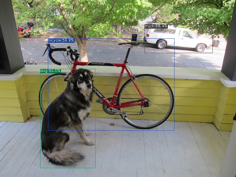
The execution method for f16 bmodel is as follows, resulting in dog_f16.jpg:

detect_yolov5 \
    --input ../image/dog.jpg \
    --model yolov5s_1684x_f16.bmodel \
    --output dog_f16.jpg

f16 bmodel

The execution method for int8 symmetric bmodel is as follows, resulting in dog_int8_sym.jpg:

detect_yolov5 \
    --input ../image/dog.jpg \
    --model yolov5s_1684x_int8_sym.bmodel \
    --output dog_int8_sym.jpg

onnx

Edit this page on GitHub
Last Updated:
Contributors: ZSL
Prev
Cross-Compilation