PWM Control
1. PWM Pins
Taking M5-R1 as an example, the board's 40PIN pins have 3 GPIOs with PWM function. Among them, PWM0 (PIN33) is already occupied by MIPI0 screen backlight.
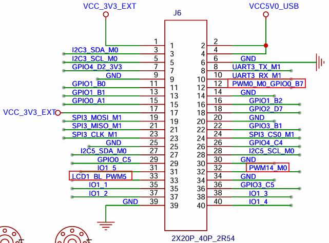
| Board | pin12 | pin32 | pin33 |
|---|---|---|---|
| M5-R1 | pwm9 | pwm13 | pwm0 |
2. Check PWM Device
Enter the following command in the terminal to check if PWM is enabled.
ls -l /sys/class/pwm/As shown in the figure:

pwmchip0 and pwmchip1 are for screen backlight and are enabled by the system by default. When multiple PWM device tree overlays are enabled, the smaller the PWM controller value, the smaller the pwmchip assigned by the system.
    For example, if I enable pwm0, pwm5, pwm14 at the same time, the following corresponding relationships will appear:

    pwm0->pwmchip0
    pwm5->pwmchip1
    pwm14->pwmchip2
3. PWM Control Method
The following takes controlling PWM2 as an example.
    # First enable pwm2 in device tree
    &pwm2 {
        status = "okay";
    };

    # Export pwm2 to user space
    echo 0 > /sys/class/pwm/pwmchip2/export

    # Set PWM period in ns
    echo 1000000 > /sys/class/pwm/pwmchip2/pwm0/period

    # Set duty cycle
    echo 500000 > /sys/class/pwm/pwmchip2/pwm0/duty_cycle

    # Set PWM polarity
    echo "normal" > /sys/class/pwm/pwmchip2/pwm0/polarity

    # Enable PWM
    echo 1 > /sys/class/pwm/pwmchip2/pwm0/enable

    # Unexport pwm14 to user space
    echo 0 > /sys/class/pwm/pwmchip2/unexport
Tips
When setting period and duty_cycle values, note that the period value must always be greater than or equal to the duty_cycle value.