HOME
Shop
  • English
  • 简体中文
HOME
Shop
  • English
  • 简体中文
  • Product Series

    • FPGA+ARM

      • GM-3568JHF

        • 1. Introduction

          • About GM-3568JHF
        • 2. Quick Start

          • 00 Introduction
          • 01 Environment Setup
          • 02 Compilation Instructions
          • 03 Flashing Guide
          • 04 Debug Tools
          • 05 Software Update
          • 06 View Information
          • 07 Test Commands
          • 08 App Compilation
          • 09 Source Code Acquisition
        • 3. Peripherals and Interfaces

          • 01 USB
          • 02 Display and Touch
          • 03 Ethernet
          • 04 WIFI
          • 05 Bluetooth
          • 06 TF-Card
          • 07 Audio
          • 08 Serial Port
          • 09 CAN
          • 10 RTC
        • 4. Application Development

          • 01 UART read and write case
          • 02 Key detection case
          • 03 LED light flashing case
          • 04 MIPI screen detection case
          • 05 Read USB device information example
          • 06 FAN Detection Case
          • 07 FPGA FSPI Communication Case
          • 08 FPGA DMA read and write case
          • 09 GPS debugging case
          • 10 Ethernet Test Cases
          • 11 RS485 reading and writing examples
          • 12 FPGA IIC read and write examples
          • 13 PN532 NFC card reader case
          • 14 TF card reading and writing case
        • 5. QT Development

          • 01 ARM64 cross compiler environment construction
          • 02 QT program added automatic startup service
        • 6. RKNN_NPU Development

          • 01 RK3568 NPU Overview
          • 02 Development Environment Setup
          • Run Official YOLOv5 Example
          • Model Conversion Detailed Explanation
          • Run Custom Model on Board
        • 7. FPGA Development

          • ARM and FPGA Communication
          • /fpga-arm/GM-3568JHF/FPGA/ch02-FPGA-Development-Manual.html
        • 8. Others

          • 01 Modification of the root directory file system
          • 02 System auto-start service
        • 9. Download

          • Download Resources
    • ShimetaPi

      • M4-R1

        • 1. Introduction

          • 1.1 About M4-R1
        • 2. Quick Start

          • 2.1 OpenHarmony Overview
          • 2.2 Image Burning
          • 2.3 Development Environment Preparation
          • 2.4 Hello World Application
        • 3. Application Development

          • 3.1 Getting Started

            • 3.1.1 ArkTS Language Overview
            • 3.1.2 UI Components (Part 1)
            • 3.1.3 UI Components (Part 2)
            • 3.1.4 UI Components (Part 3)
          • 3.2 Advanced

            • 3.2.1 Getting Started Guide
            • 3.2.2 Usage of Third Party Libraries
            • 3.2.3 Deployment of the Application
            • 3.2.4 Factory Reset
            • 3.2.5 System Debug
            • 3.2.6 APP Stability Testing
            • 3.2.7 Application Testing
          • 3.3 Getting Docs

            • 3.3.1 Official Website Information
          • 3.4 Development Instructions

            • 3.4.1 Full SDK
            • 3.4.2 Introduction of Third Party Libraries
            • 3.4.3 Introduction of HDC Tool
            • 3.4.4 Restore Factory Mode
            • 3.4.5 Update System API
          • 3.5 First Application

            • 3.5.1 First ArkTS App
          • 3.6 Application Demo

            • 3.6.1 UART Tool
            • 3.6.2 Graphics Tablet
            • 3.6.3 Digital Clock
            • 3.6.4 WIFI Tool
        • 4. Device Development

          • 4.1 Ubuntu Environment Development

            • 4.1.1 Environment Setup
            • 4.1.2 Download Source Code
            • 4.1.3 Compile Source Code
          • 4.2 Using DevEco Device Tool

            • 4.2.1 Tool Introduction
            • 4.2.2 Environment Construction
            • 4.2.3 Import SDK
            • 4.2.4 Function Introduction
        • 5. Peripherals and Interfaces

          • 5.1 Raspberry Pi Interfaces
          • 5.2 GPIO Interface
          • 5.3 I2C Interface
          • 5.4 SPI Communication
          • 5.5 PWM Control
          • 5.6 Serial Port Communication
          • 5.7 TF Card Slot
          • 5.8 Display Screen
          • 5.9 Touch Screen
          • 5.10 Audio
          • 5.11 RTC
          • 5.12 Ethernet
          • 5.13 M.2
          • 5.14 MINI PCIE
          • 5.15 Camera
          • 5.16 WIFI BT
          • 5.17 HAT
        • 6. FAQ

          • 6.1 Download Link
      • M5-R1

        • 1. Introduction

          • M5-R1 Development Documentation
        • 2. Quick Start

          • OpenHarmony Overview
          • Image Burning
          • Development Environment Preparation
          • Hello World Application and Deployment
        • 3. Peripherals and Interfaces

          • 3.1 Raspberry Pi Interfaces
          • 3.2 GPIO Interface
          • 3.3 I2C Interface
          • 3.4 SPI Communication
          • 3.5 PWM Control
          • 3.6 Serial Port Communication
          • 3.7 TF Card Slot
          • 3.8 Display Screen
          • 3.9 Touch Screen
          • 3.10 Audio
          • 3.11 RTC
          • 3.12 Ethernet
          • 3.13 M.2
          • 3.14 MINI PCIE
          • 3.15 Camera
          • 3.16 WIFI BT
          • 3.17 HAT
        • 4. Application Development

          • 4.1 Getting Started

            • 4.1.1 ArkTS Language Overview
            • 4.1.2 UI Components (Part 1)
            • 4.1.3 UI Components (Part 2)
            • 4.1.4 UI Components (Part 3)
          • 4.2 Advanced

            • 4.2.1 Getting Started Guide
            • 4.2.2 Usage of Third Party Libraries
            • 4.2.3 Deployment of the Application
            • 4.2.4 Factory Reset
            • 4.2.5 System Debug
            • 4.2.6 APP Stability Testing
            • 4.2.7 Application Testing
        • 5. Device Development

          • 5.1 Environment Setup
          • 5.2 Download Source Code
          • 5.3 Compile Source Code
        • 6. Download

          • Data Download
    • OpenHarmony

      • SC-3568HA

        • 1. Introduction

          • 1.1 About SC-3568HA
        • 2. Quick Start

          • 2.1 OpenHarmony Overview
          • 2.2 Image Burning
          • 2.3 Development Environment Preparation
          • 2.4 Hello World Application
        • 3. Application Development

          • 3.1 ArkUI

            • 3.1.1 ArkTS Language Overview
            • 3.1.2 UI Components (Part 1)
            • 3.1.3 UI Components (Part 2)
            • 3.1.4 UI Components (Part 3)
          • 3.2 Advanced

            • 3.2.1 Getting Started Guide
            • 3.2.2 Usage of Third Party Libraries
            • 3.2.3 Deployment of the Application
            • 3.2.4 Factory Reset
            • 3.2.5 System Debug
            • 3.2.6 APP Stability Testing
            • 3.2.7 Application Testing
        • 4. Device Development

          • 4.1 Environment Setup
          • 4.2 Download Source Code
          • 4.3 Compile Source Code
        • 5. Peripherals and Interfaces

          • 5.1 Raspberry Pi Interfaces
          • 5.2 GPIO Interface
          • 5.3 I2C Interface
          • 5.4 SPI Communication
          • 5.5 PWM Control
          • 5.6 Serial Port Communication
          • 5.7 TF Card Slot
          • 5.8 Display Screen
          • 5.9 Touch Screen
          • 5.10 Audio
          • 5.11 RTC
          • 5.12 Ethernet
          • 5.13 M.2
          • 5.14 MINI PCIE
          • 5.15 Camera
          • 5.16 WIFI BT
          • 5.17 HAT
        • 6. FAQ

          • 6.1 Download Link
      • M-K1HSE

        • 1. Introduction

          • 1.1 Product Introduction
        • 2. Quick Start

          • 2.1 Debug Tool Installation
          • 2.2 Development Environment Setup
          • 2.3 Source Code Download
          • 2.4 Build Instructions
          • 2.5 Flashing Guide
          • 2.6 APT Update Sources
          • 2.7 View Board Info
          • 2.8 CLI LED and Key Test
          • 2.9 GCC Build Programs
        • 3. Application Development

          • 3.1 Basic Application Development

            • 3.1.1 Development Environment Preparation
            • 3.1.2 First Application HelloWorld
            • 3.1.3 Develop HAR Package
          • 3.2 Peripheral Application Cases

            • 3.2.1 UART Read/Write
            • 3.2.2 Key Demo
            • 3.2.3 LED Flash
        • 4. Peripherals and Interfaces

          • 4.1 Standard Peripherals

            • 4.1.1 USB
            • 4.1.2 Display and Touch
            • 4.1.3 Ethernet
            • 4.1.4 WIFI
            • 4.1.5 Bluetooth
            • 4.1.6 TF Card
            • 4.1.7 Audio
            • 4.1.8 Serial Port
            • 4.1.9 CAN
            • 4.1.10 RTC
          • 4.2 Interfaces

            • 4.2.1 Audio
            • 4.2.2 RS485
            • 4.2.3 Display
            • 4.2.4 Touch
        • 5. System Customization Development

          • 5.1 System Porting
          • 5.2 System Customization
          • 5.3 Driver Development
          • 5.4 System Debugging
          • 5.5 OTA Upgrade
        • 6. Download

          • 6.1 Download
    • EVS-Camera

      • CF-NRS1

        • 1. Introduction

          • 1.1 About CF-NRS1
          • 1.2 Event-Based Concepts
          • 1.3 Quick Start
          • 1.4 Resources
        • 2. Development

          • 2.1 Development Overview

            • 2.1.1 Shimetapi Hybrid Camera SDK Introduction
          • 2.2 Environment & API

            • 2.2.1 Environment Overview
            • 2.2.2 Development API Overview
          • 2.3 Linux Development

            • 2.3.1 Linux SDK Introduction
            • 2.3.2 Linux SDK API
            • 2.3.3 Linux Algorithm
            • 2.3.4 Linux Algorithm API
          • 2.4 Service & Web

            • 2.4.1 EVS Server
            • 2.4.2 Time Server
            • 2.4.3 EVS Web
        • 3. Download

          • 3.1 Download
        • 4. Common Problems

          • 4.1 Common Problems
      • CF-CRA2

        • 1. Introduction

          • 1.1 About CF-CRA2
        • 2. Download

          • 2.1 Download
      • EVS Module

        • 1. Related Concepts
        • 2. Hardware Preparation and Environment Configuration
        • 3. Example Program User Guide
        • Resources Download
    • AI-model

      • 1684XB-32T

        • 1. Introduction

          • AIBOX-1684XB-32 Introduction
        • 2. Quick Start

          • First time use
          • Network Configuration
          • Disk usage
          • Memory allocation
          • Fan Strategy
          • Firmware Upgrade
          • Cross-Compilation
          • Model Quantization
        • 3. Application Development

          • 3.1 Development Introduction

            • Sophgo SDK Development
            • SOPHON-DEMO Introduction
          • 3.2 Large Language Models

            • Deploying Llama3 Example
            • /ai-model/AIBOX-1684XB-32/application-development/LLM/Sophon_LLM_api_server-Development-AIBOX-1684XB-32.html
            • /ai-model/AIBOX-1684XB-32/application-development/LLM/MiniCPM-V-2_6-AIBOX-1684XB-32.html
            • /ai-model/AIBOX-1684XB-32/application-development/LLM/Qwen-2-5-VL-demo-Development-AIBOX-1684XB-32.html
            • /ai-model/AIBOX-1684XB-32/application-development/LLM/Qwen-3-chat-demo-Development-AIBOX-1684XB-32.html
            • /ai-model/AIBOX-1684XB-32/application-development/LLM/Qwen3-Qwen Agent-MCP.html
            • /ai-model/AIBOX-1684XB-32/application-development/LLM/Qwen3-langchain-AI Agent.html
          • 3.3 Deep Learning

            • ResNet (Image Classification)
            • LPRNet (License Plate Recognition)
            • SAM (Universal Image Segmentation Foundation Model)
            • YOLOv5 (Object Detection)
            • OpenPose (Human Keypoint Detection)
            • PP-OCR (Optical Character Recognition)
        • 4. Download

          • Resource Download
      • 1684X-416T

        • 1. Introduction

          • AIBOX-1684X-416 Introduction
        • 2. Demo Simple Operation Guide

          • Simple instructions for using shimeta smart monitoring demo
      • RDK-X5

        • 1. Introduction

          • RDK-X5 Hardware Introduction
        • 2. Quick Start

          • RDK-X5 Quick Start
        • 3. Application Development

          • 3.1 AI Online Model Development

            • AI Online Development - Experiment01
            • AI Online Development - Experiment02
            • AI Online Development - Experiment03
            • AI Online Development - Experiment04
            • AI Online Development - Experiment05
            • AI Online Development - Experiment06
          • 3.2 Large Language Models (Voice)

            • Voice LLM Application - Experiment01
            • Voice LLM Application - Experiment02
            • Voice LLM Application - Experiment03
            • Voice LLM Application - Experiment04
            • Voice LLM Application - Experiment05
            • Voice LLM Application - Experiment06
          • 3.3 40pin-IO Development

            • 40pin IO Development - Experiment01
            • 40pin IO Development - Experiment02
            • 40pin IO Development - Experiment03
            • 40pin IO Development - Experiment04
            • 40pin IO Development - Experiment05
            • 40pin IO Development - Experiment06
            • 40pin IO Development - Experiment07
          • 3.4 USB Module Development

            • USB Module Usage - Experiment01
            • USB Module Usage - Experiment02
          • 3.5 Machine Vision

            • Machine Vision Technology Development - Experiment01
            • Machine Vision Technology Development - Experiment02
            • Machine Vision Technology Development - Experiment03
            • Machine Vision Technology Development - Experiment04
          • 3.6 ROS2 Base Development

            • ROS2 Basic Development - Experiment01
            • ROS2 Basic Development - Experiment02
            • ROS2 Basic Development - Experiment03
            • ROS2 Basic Development - Experiment04
      • RDK-S100

        • 1. Introduction

          • 1.1 About RDK-S100
        • 2. Quick Start

          • 2.1 First Use
        • 3. Application Development

          • 3.1 AI Online Model Development

            • 3.1.1 Volcano Engine Doubao AI
            • 3.1.2 Image Analysis
            • 3.1.3 Multimodal Visual Analysis
            • 3.1.4 Multimodal Image Comparison
            • 3.1.5 Multimodal Document Analysis
            • 3.1.6 Camera AI Vision Analysis
          • 3.2 Large Language Models

            • 3.2.1 Speech Recognition
            • 3.2.2 Voice Conversation
            • 3.2.3 Multimodal Image Analysis
            • 3.2.4 Multimodal Image Comparison
            • 3.2.5 Multimodal Document Analysis
            • 3.2.6 Multimodal Vision Application
          • 3.3 40pin-IO Development

            • 3.3.1 GPIO Output LED Blink
            • 3.3.2 GPIO Input
            • 3.3.3 Key Control LED
            • 3.3.4 PWM Output
            • 3.3.5 Serial Output
            • 3.3.6 I2C Experiment
          • 3.4 USB Module Development

            • 3.4.1 USB Voice Module
            • 3.4.2 Sound Source Localization
          • 3.5 Machine Vision

            • 3.5.1 USB Camera
            • 3.5.2 Image Processing Basics
            • 3.5.3 Object Detection
            • 3.5.4 Image Segmentation
          • 3.6 ROS2 Base Development

            • 3.6.1 Environment Setup
            • 3.6.2 Create and Build Workspace
            • 3.6.3 ROS2 Topic Communication
            • 3.6.4 ROS2 Camera Application
    • Core-Board

      • C-3568BQ

        • 1. Introduction

          • C-3568BQ Introduction
      • C-3588LQ

        • 1. Introduction

          • C-3588LQ Introduction
      • GC-3568JBAF

        • 1. Introduction

          • GC-3568JBAF Introduction
      • C-K1BA

        • 1. Introduction

          • C-K1BA Introduction

Driver Development

Sensor driver development

  • Overview

Sensor is a common input device used to sense the state of the environment and achieve corresponding responses. Compared with the original Linux driver mode, OH implements the sensor driver in the HDF (Hardware Driver Foundation) layer. This implementation method can achieve one-time development and support deployment in different kernel environments, such as lightweight systems, small systems or standard Linux systems. In addition, in the HDF framework, different drivers can be managed uniformly, and each driver can provide services to the outside world. For the application layer, it only needs to call the HDI (Hardware Device Interface) interface to obtain the driver service capabilities.

Sensor Driven Model

The Sensor driver model based on the HDF driver framework in OpenHarmony is as follows:

FIRMWARE

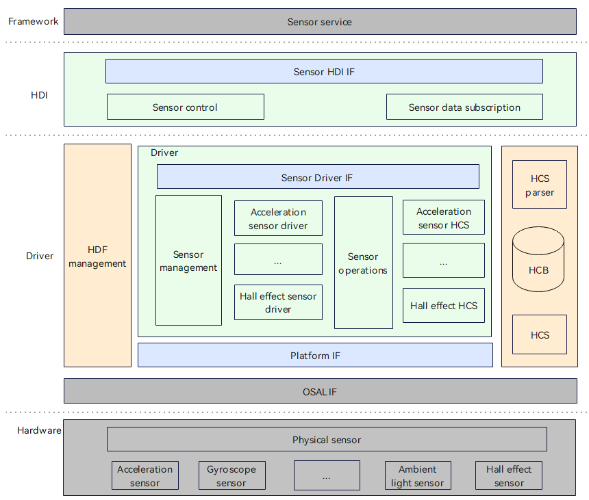
The sensor driver model shields the differences in hardware devices and provides a stable sensor basic capability interface for the upper-level sensor service system, including sensor list query, sensor start and stop, sensor subscription and unsubscription, sensor parameter configuration and other functions.

The development of sensor device drivers is based on the HDF driver framework, combining the operating system abstraction layer (OSAL) and platform driver interface (such as I2C/SPI/UART bus and other platform resources) capabilities to shield the differences in bus resources between different operating systems and platforms, and achieve the goal of "one-time development, multi-system deployment" for sensor drivers.

The sensor driver model in OpenHarmony is divided into the following levels:

Hardware: This layer determines how the sensor device is connected to the CPU, what method the peripheral uses to communicate (such as I2C, SPI, GPIO, etc.), etc. Driver: This layer implements hardware peripheral drivers, including bindInit and realese functions in HdfDriverEntry, and ReadData in data OpsCall. HDI: Interface definition and implementation. The interface mainly includes all stable interfaces such as sensor information query, sensor start and stop, sensor subscription/unsubscription, sensor parameter configuration, etc., to simplify service development. Framework: Upper-level sensor service.

HCS Configuration

For different platforms, you need to modify the corresponding hcs file in the corresponding platform directory. The following example shows the modification method for adding a sensor module under the smt001 platform. Configure device_info.hcs File path: vendor/spacemit/smt001/hdf_config/khdf/device_info/device_info.hcs Configuration instructions: Add the following information in device_info.hcs.

Main field description:

policy: service policy. The value "0" means not to publish the service, the value "1" means to publish the service to the kernel state, and the value "2" means to publish the service to the user state. moduleName: the same as the moduleName in the HdfDriverEntry structure implemented by the driver. deviceMatchAttr: the private configuration information of the driver. serviceName: the service name, and the serviceName node will eventually be generated under the /dev/ node (the prerequisite for generating the node is that the policy is configured to be greater than or equal to 1).

Configure sensor_config.hcs

File path: vendor/spacemit/smt001/hdf_config/khdf/sensor/sensor_config.hcs Configuration instructions: Add the following content to sensor_config.hcs: #include "accel/accel_qm8658_config.hcs"

Configure accel_qm8658_config.hcs File path: vendor/spacemit/smt001/hdf_config/khdf/sensor/accel/accel_qm8658_config.hcs

Configuration instructions: Add a new folder accel and create a new file accel_qm8658_config.hcs. The file content is as follows:

#include"../sensor_common.hcs"
root{
    accel_qm8658_chip_config:sensorConfig{
        match_attr="hdf_sensor_accel_qm8658_driver";
        sensorInfo::sensorDeviceInfo{
            sensorName="accelerometer";
            vendorName="qmi8658";//maxstringlengthis16bytes
            sensorTypeId=1; //enum SensorTypeTag
            sensorId=1;//userdefinesensorid
            power=230;
        }
        sensorBusConfig::sensorBusInfo{
            busType=0; //0:i2c1:spi
            busNum=3;
            busAddr=0x6a;
            regWidth=1;//1btye
        }
        sensorIdAttr::sensorIdInfo{
            chipName="qm8658";
            chipIdRegister=0x00;
            chipIdValue=0x05;
        }
        sensorRegConfig{
            /*regAddr:registeraddress
            value:configregistervalue
            len:sizeofvalue
            mask:maskofvalue
            delay:configregisterdelaytime(ms)
            opsType:enumSensorOpsType0-none1-read2-write3-read_check4-update_bit
            calType:enumSensorBitCalType0-none1-set2-revert3-xor4-leftshift5-rightshift
            shiftNum:shiftbits
            debug:0-nodebug1-debug
            save:0-nosave1-save
            */
            /*regAddr,value,mask,len,delay,opsType,calType,shiftNum,debug,save*/
            initSeqConfig=[
                0x02,0x78, 0xff,1,5, 2,0,0,0,0,
                0x03,0x26, 0xff,1,5, 2,0,0,0,0,
                0x08,0x00,0x03,1,5, 2,0,0,0,0
            ];
            enableSeqConfig=[
                0x08,0x01,0x03,1,5, 2,0,0,0,0
            ];
            disableSeqConfig=[
                0x08,0x00,0x03,1,5, 2,0,0,0,0
            ];
        }
    }
}

Compile option modification

Add the following content in drivers/hdf_core/adapter/khdf/linux/model/sensor/Kconfig:

config DRIVERS_HDF_SENSOR_ACCEL_QM8658
    bool "Enable HDF accel qm8658 sensor driver"
    default n
    depends on DRIVERS_HDF_SENSOR_ACCEL
    help
        Answer Y to enable HDF accel qm8658 sensor driver.

Add the following content in drivers/hdf_core/adapter/khdf/linux/model/sensor/Makefile: obj-$(CONFIG_DRIVERS_HDF_SENSOR_ACCEL_QM8658)+=$(SENSOR_ROOT_DIR)/chipset/accel/accel_qm8658.o Modify the corresponding driver implementation file of Makefile as follows:

drivers/peripheral/sensor/chipset/accel/accel_qm8658.c
drivers/peripheral/sensor/chipset/accel/accel_qm8658.h

Kernel defconfig configuration

Add the following content to kernel/linux/spacemit_kernel-6.6/arch/riscv/configs/k1_defconfig file:

CONFIG_DRIVERS_HDF_SENSOR=y
CONFIG_DRIVERS_HDF_SENSOR_ACCEL=y
CONFIG_DRIVERS_HDF_SENSOR_ACCEL_QM8658=y

Application Code Directory Description

The interface implementations of the Sensor driver's external services are all in the drivers/peripheral/sensor path. The corresponding functions of this directory are described as follows:

/drivers/peripheral/sensor
├── hal
    └── include
    └── src
├── interfaces
    └── include
├── test
    └── unit
hal: HAL layer code for the sensor module  
include: Internal header files for the sensor module's HAL layer  
src: Implementation of the sensor module's HAL layer code  
interfaces: Driver capability interfaces provided by the sensor module to upper-layer services  
include: Interface definitions exposed by the sensor module  
test: Test code for the sensor module  
unit: Unit test code for the sensor module

Common Problem Solving

Confirm the accuracy of HCS configuration, including I2C bus, Sensor register initialization, Sensor enable, etc. Confirm whether the compilation options have been modified to compile it normally. If the application cannot be enabled, confirm whether the module needs to be configured with permissions and whether to touch hdf.hcs to change the timestamp.

TouchScreen driver development

Overview

TouchScreen is a common input device that senses the user's touch on the screen and responds accordingly. Compared with the original Linux driver mode, OpenHarmony implements the TouchScreen driver in the HDF layer. This implementation method can achieve one-time development and support deployment in different kernel environments, such as lightweight systems, small systems, or standard Linux systems. In addition, in the HDF framework, different drivers can be managed uniformly, and each driver can provide services to the outside world. For the application layer, it only needs to call the HDI interface to obtain the driver service capabilities.

TouchScreen driver model

The TouchScreen driver model based on the HDF driver framework in OpenHarmony is as follows:

FIRMWARE

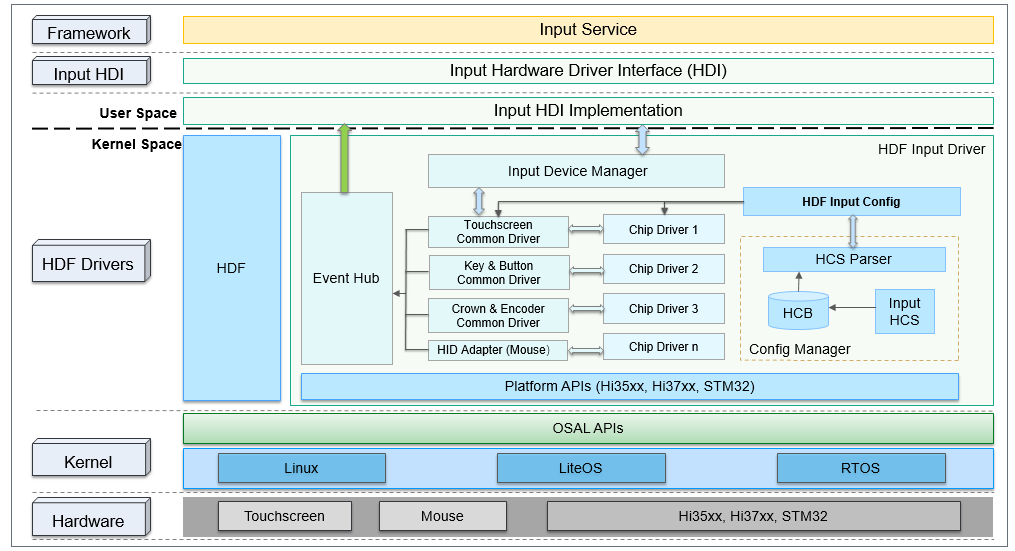
The TouchScreen driver model in OpenHarmony is divided into the following layers: Hardware: This layer determines how the TouchScreen device is connected to the CPU, which IO ports the peripherals are configured through, what method (such as I2C, SPI, UART, etc.) is used for communication, etc. Kernel: This layer mainly selects the appropriate kernel (Linux/LiteOS/RTOS) according to the needs of the project; the OSAL APIs in the Kernel layer are mainly used to normalize different kernels, provide a standardized operation interface for the HDF Drivers layer, and shield the differences between different kernels from causing modifications to the upper layer to the greatest extent.

HDF Drivers: This layer implements hardware peripheral drivers and completes the initialization of different peripherals. For example, TouchScreen needs to implement the Init, Detect, Resume, Suspend, DataHandle, and UpdateFirmware functions in struct TouchChipOps ops. Input HDI: This layer implements driver interface capabilities such as TouchScreen device management, business control, and data reporting, and provides hardware driver capabilities for the upper layer. Framework: Upper-layer TouchScreen services.

HCS Configuration

For different platforms, you need to modify the corresponding hcs file in the corresponding platform directory. The following example shows the modification method for adding a GT9271 touch screen under the smt001 platform.

Configure device_info.hcs File path: vendor/spacemit/smt001/hdf_config/khdf/device_info/device_info.hcs Configuration instructions: Add the following content to device_info.hcs.

Main field description:

policy: service policy. The value "0" means not to publish the service, the value "1" means to publish the service to kernel mode, and the value "2" means to publish the service to kernel user mode. moduleName: the same as the moduleName in the HdfDriverEntry structure implemented by the driver. deviceMatchAttr: the private configuration information of the driver. serviceName: the service name, and the serviceName node will eventually be generated under the /dev/ node (the prerequisite for generating the node is that the policy is configured to be greater than or equal to 1).

Configure input_config.hcs

File path: vendor/spacemit/smt001/hdf_config/khdf/input/input_config.hcs Configuration instructions: Modify the following configuration in input_config.hcs.

Modify the configuration and add chip4 in the chipConfig field to indicate a new touch screen driver.

Compile option modification

The following takes the driver of the newly added touch screen GT9271 as an example to introduce the relevant compilation option modifications.

Add the following content in drivers/hdf_core/adapter/khdf/linux/model/input/Kconfig:

config DRIVERS_HDF_TP_10P10_GT9271
    bool "Enable HDF tp10P10 GT9271

UART driver development

Overview

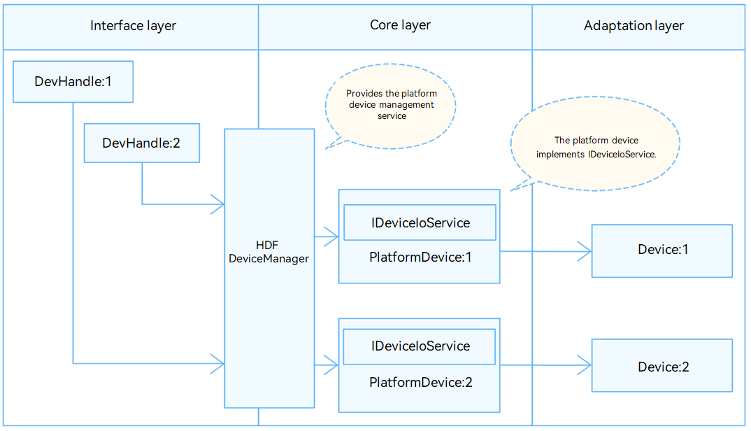
UART refers to Universal Asynchronous Receiver/Transmitter. In the HDF framework, the interface adaptation mode of UART adopts the independent service mode. In this mode, each device object will independently publish a device service to handle external access. After the device manager receives the access request from the API, it extracts the parameters of the request to achieve the purpose of calling the corresponding internal method of the actual device object. The advantage of the independent service mode is that it can directly use the service management capabilities of HDFDeviceManager, but it also has certain shortcomings, that is, it is necessary to configure the device node for each device separately, which will increase the memory usage. The structure diagram of the UART independent service mode is shown in the figure below.

FIRMWARE

DTS Configuration

Configuration Instructions

Configure the corresponding serial port device node, for example, configure serial port 2:

&uart2 {
    pinctrl-names = "default";
    pinctrl-0 = <&pinctrl_uart2>;
    status = "okay";
};

HCS Configuration

For different platforms, you need to modify the corresponding hcs file in the corresponding platform directory.

Configuring device_info.hcs

File Path

vendor/spacemit/xxx/hdf_config/khdf/device_info/device_info.hcs

Configuration Instructions

Add the following content to device_info.hcs:

During the configuration process, pay attention to the following points:

Policy: Set the node to hide or show. The value "1" means hiding, that is, HDF nodes are not displayed in the dev directory; the value "2" means showing, that is, HDF nodes are displayed in the dev directory. Permission: file permissions. Priority: startup sequence, the larger the value, the later it starts. The suffix "2" of "HDF_PLATFORM_UART_2" in serviceName: corresponds to the port parameter of the application open function.

deviceMatchAttr: must be consistent with the match_attr value in rk3568_uart_config.hcs.

Configure rk3568_uart_config.hcs

File Path

vendor/spacemit/xxx/hdf_config/khdf/platform/rk3568_uart_config.hcs

Configuration Instructions

Modify rk3568_uart_config.hcs as follows:

During the configuration process, pay attention to the following points:

The suffix "0x0002" in device_uart_0x0002 is the serial port number, starting from 0x0000. Num: It is combined with the driver_name value "ttyS" to form the driver device name, such as ttyS9.

If the driver device name does not start with ttyS, for example, the driver device names of serial ports A to D of the RK3568A board start with ttyXRUSB, you need to modify the driver_name. For example:

device_uart_0x0002 :: uart_device {
    num = 9;
    driver_name = "ttyXRUSB"
    match_attr = "rockchip_rk3568_uart_9";
}

If you do not modify the driver_name, the driver_name value in the template, that is, "ttyS", is used by default.

Application usage process

For details on how to use the UART API interface, see the OHOS API documentation.

Commonly used UART APIs are described as follows: uartOpen(port: number): port is the suffix number of serviceName in the "Configure device_info.hcs" section. uartSetBaud: Set the baud rate of the specified serial port. uartSetAttribute: Set the basic attributes of the specified serial port.

Common Problem Solving

Confirm whether there is a tty device generated under /dev/. If not, please refer to the "DTS Configuration" section to check the configuration. Confirm whether there is HDF_PLATFORM_UART_x generated under /dev/ (x is the configured service_name). If not, please refer to the "HCS Configuration" section to check the configuration.

Data read and write does not work: Short RX and TX, and test through two hdc terminals, one cat tty node and one echo tty node. If the cat terminal does not receive data: Please make sure that the pinctrl - 0 in the "DTS Configuration" section selects the correct serial port pin. Check and ensure that the hardware circuit is normal.

Sending is normal, but reading data is lost: Please check whether there are other applications grabbing data.

Check for hardware interference.

Edit this page on GitHub
Last Updated:
Contributors: ZSL
Prev
5.2 System Customization
Next
5.4 System Debugging