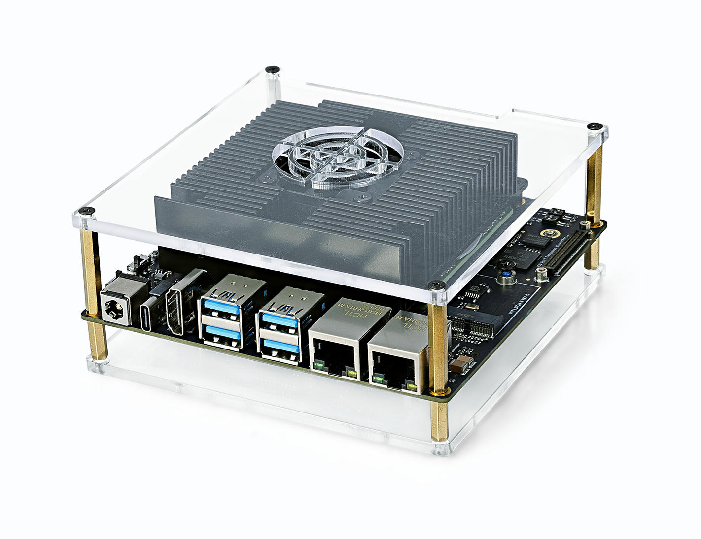
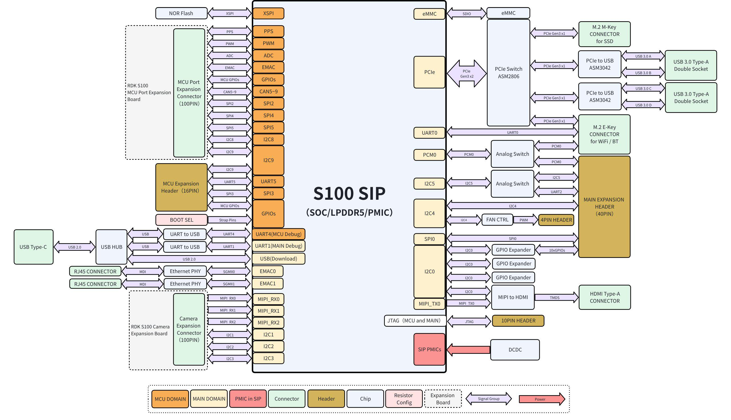
RDK-S100 Hardware Introduction
1.2.1 RDK S100 Series
Precautions
- It is prohibited to hot-swap any equipment other than USB, HDMI, and Ethernet cables when the power is on
- Use power adapters from reputable brands; otherwise, power supply abnormalities may occur, leading to system abnormal shutdowns
- It is recommended to use the onboard POWER ON/OFF button to power the main board on/off, and insert/remove the DC connector when the adapter is powered off.
Flashing Preparation
Power Supply
The RDK S100 development board is powered through the DC interface. It is recommended to use the power adapter included in the kit.
Storage
RDK S100 uses eMMC as the system boot medium.
Display
The RDK S100 development board supports HDMI display interface. By connecting the development board to a display using the corresponding cable, graphical desktop display can be achieved.
Network Connection
RDK S100 development board supports Ethernet and Wi-Fi network interfaces. Users can achieve network connection through either interface.
Driver Download
Installing USB Drivers
For Windows operating system, before using adb and fastboot functions, you need to confirm whether the corresponding driver is installed.
Enter fastboot 0 in the development board's uboot command line to enter fastboot mode:
Warning: eth1 (eth0) using random MAC address - 9a:07:de:92:a2:c5
eth0: eth1
system_slot: 0 adc_boardinfo: 6a84
strap_pin = 0x45bc0 bootinfo = 0x0 bootcount = 0x1
boot_block_device [1]
flash boot
success!
Hit any key to stop autoboot: 0
Hobot$
Hobot$
Hobot$ fastboot 0
At this point, the device manager will prompt the existence of an unknown device for USB download gadget.
When the driver is not installed, the device manager will prompt the existence of an unknown device for USB download gadget, as shown in the figure below:
USB driver download: (Available in the download resource summary)
Download the sunrise5_winusb.zip package for driver installation. The steps are as follows:
- Extract sunrise5_winusb.zip.
- Enter the sunrise5_winusb folder, right-click on install_driver.bat, and select "Run as administrator".
After successful driver installation, the device manager will display the Android Device, as shown in the figure below:
System Flashing
The RDK S100 kit currently provides Ubuntu 22.04 system image, which supports Desktop desktop graphical interaction.
Note
RDK S100 is factory-flashed with a test version system image. To ensure you are using the latest version of the system, it is recommended to complete the latest system image flashing by referring to this document.
Image Download
Whole System Flashing
Note: Currently, it is necessary to set SW3 to the ↑ position to use the onboard eMMC for booting. Booting from M.2 NVMe SSD is not temporarily supported.
The RDK S100 development kit can use the PC tool D-Navigation to complete the Ubuntu system flashing. Currently, this flashing process supports two USB download modes, which can be selected in the "Download Selection" interface of the flashing tool under the "Download Mode" option. The specific differences between these two modes are as follows:
- U-Boot Flashing Method: This mode relies on RDK S100 entering U-Boot flashing mode (i.e., fastboot mode). It is more frequently used in daily flashing scenarios and can meet most conventional system flashing needs.
- USB Flashing Method: This mode is based on the DFU protocol. When RDK S100 cannot enter U-Boot mode, or the system is damaged causing the device to become bricked, this mode can be used to help recover the system.
The specific flashing steps using the PC tool D-Navigation are provided below.
Note: D-Navigation on Windows PC can only be used after successful driver installation. Please ensure the driver is installed successfully before use.
Tip: Before flashing the Ubuntu system image, the following preparations are needed:
- Prepare a Type-C data cable. Connect one end to the board's Type-C interface and the other end to the PC.
- Download the image flashing tool D-Navigation. According to the different systems, there are three ways to start the Diguachip tool D-Navigation:
- Windows version startup:
Double-click to open D-Navigation.exe
- Ubuntu version startup:
xhost + sudo ./D-Navigation --no-sandbox
- MacOS version startup (currently supports M chip):
xhost -cr D-navigation.app # App解除隔离,在终端执行 Double-click to open D-Navigation.exe
Uboot Flashing
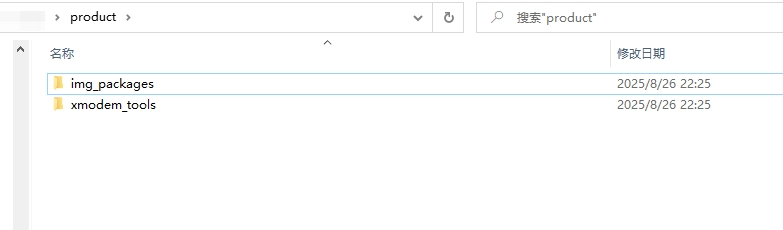
- Prepare the RDK S100 image package (RDK-S100 resource summary - product.zip)
- After extracting, you get the product folder. The structure is as follows. Ensure that within the same folder, there is the img_packages folder and xmodem_tools file
- Power on the development board
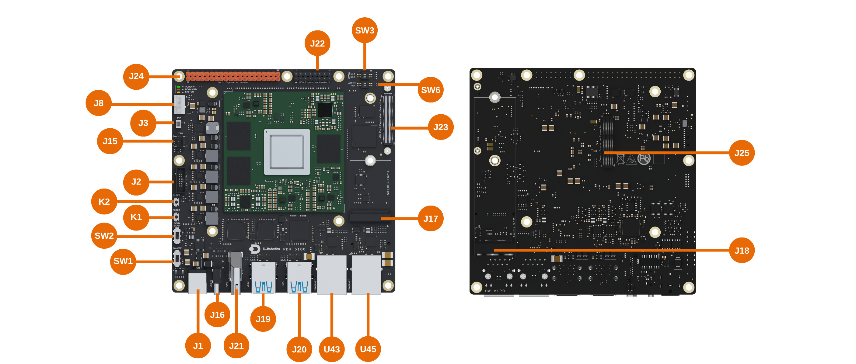
Tip: The U-Boot method requires exclusive access to the serial port, so ensure the port is not used by other devices or applications.
- Open the Diguachip tool D-Navigation and complete the following operations:
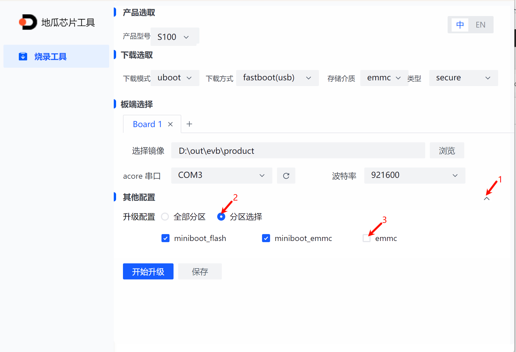
- Select product model: S100
- Download mode: uboot; storage medium: emmc; type: secure
- Click Browse to select the firmware's product folder
- Select the serial port connected to RDK S100, baud rate 921600
- Click Start Upgrade (During the upgrade process, if there is a 'Need manual reset' prompt, please repower the device)
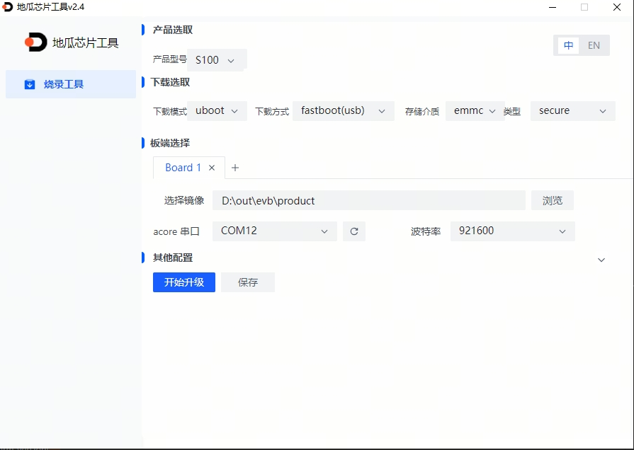
- Repower after the upgrade is complete
USB Flashing (Empty Chip Flashing or Reflashing)
- Prepare the RDK S100 image package (RDK-S100 resource summary - product.zip)
- After extracting, you get the product folder. The structure is as follows. Ensure that within the same folder, there is the img_packages folder and xmodem_tools file
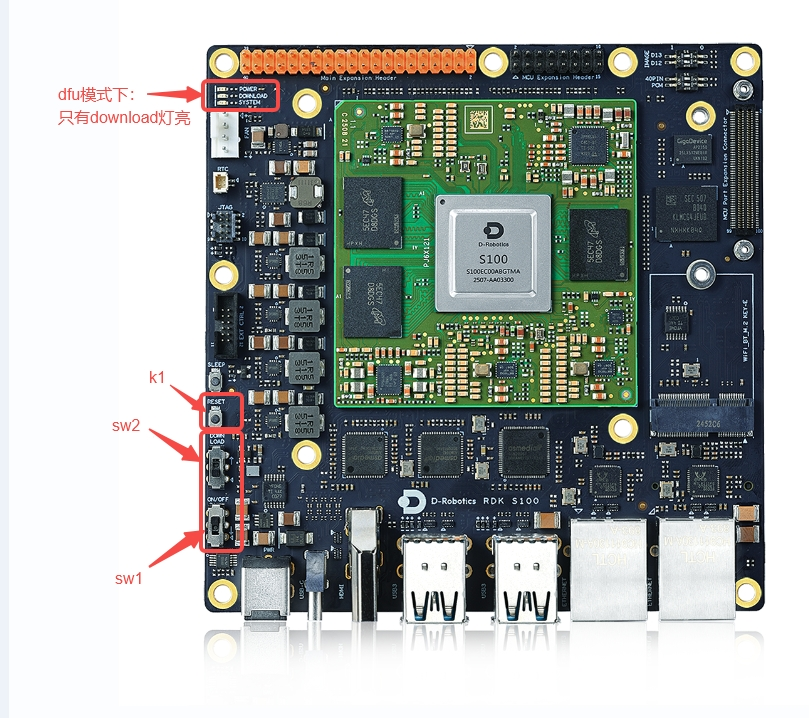
- Switch the device to DFU mode. The specific steps are:
- Set SW1 to ↑, turn off power
- Set SW2 to ↑, enter Download mode
- Set SW1 to ▽, turn on power
- If the DOWNLOAD light is on, DFU mode is entered. Otherwise, press K1 to reset the system.
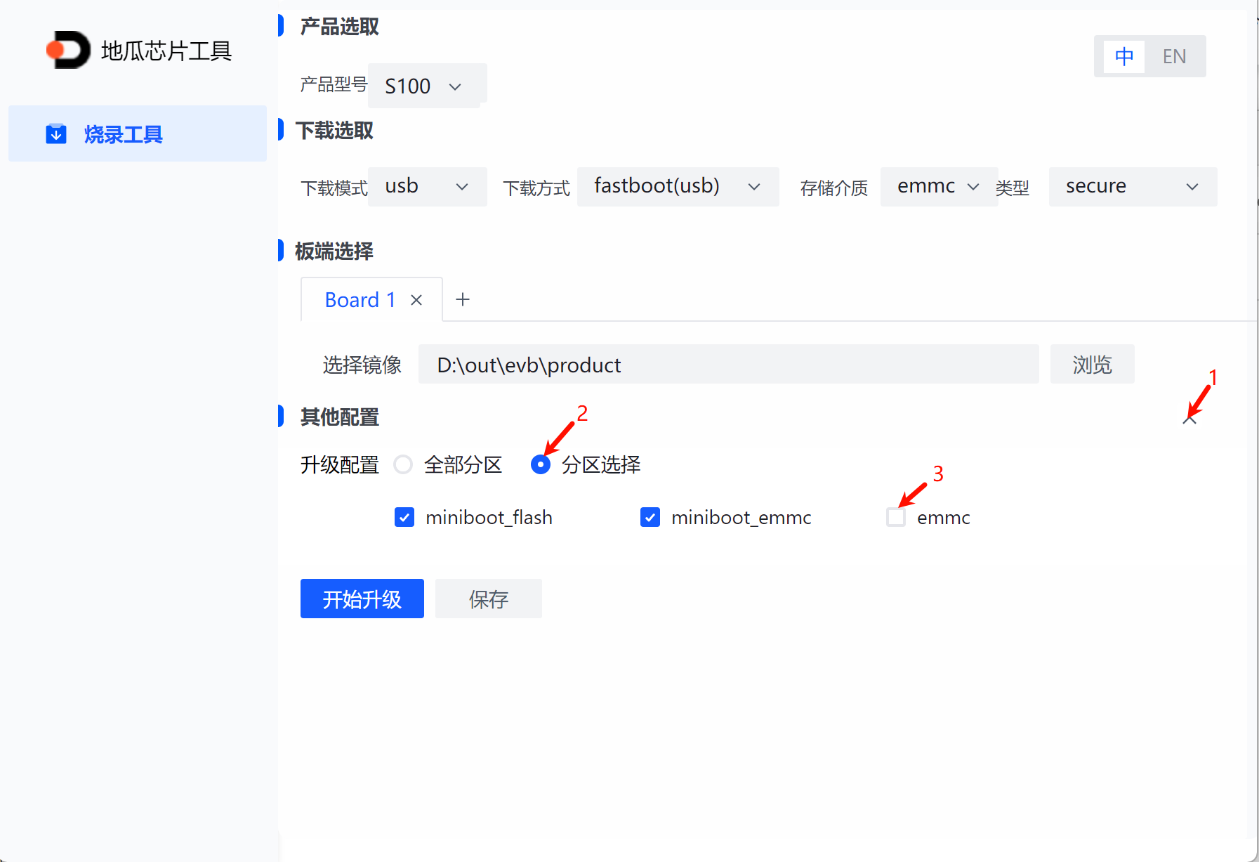
- Open the Diguachip tool D-Navigation and complete the following operations
- Select product model: S100
- Download mode: usb; storage medium: emmc; type: secure
- Click Browse to select the firmware's product folder
- Power off and restart the device, click Start Upgrade, wait for upgrade to complete
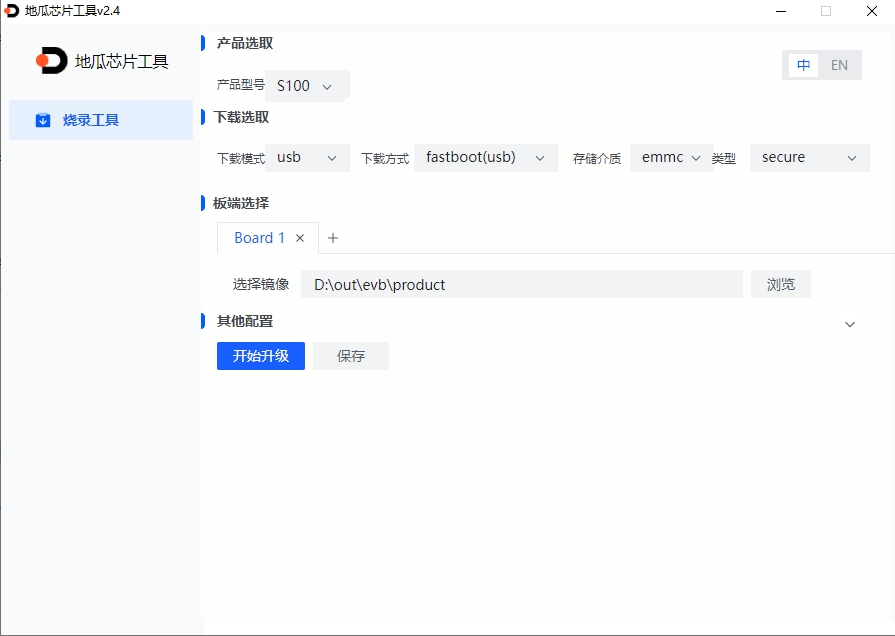
- After the upgrade is complete, turn off power, move the flashing switch downward (to exit DFU mode), and repower.
Miniboot and File System Upgrade
The D-Navigation tool supports updating the [Miniboot image] for S100. When customers need to preserve root file system modifications (such as self-installed python/deb packages), they can upgrade the file system on the board using sudo apt update && sudo apt upgrade, and then use the D-Navigation tool for Miniboot image upgrade.
The overall Miniboot system flashing process is the same as [whole system flashing], with additional configuration needed:
- Click the arrow on the far right of "Other Configuration";
- Click and select "Partition Selection";
- Uncheck "emmc";
Uboot flashing example is shown in the figure below:
USB flashing example configuration is shown in the figure below:
System Startup
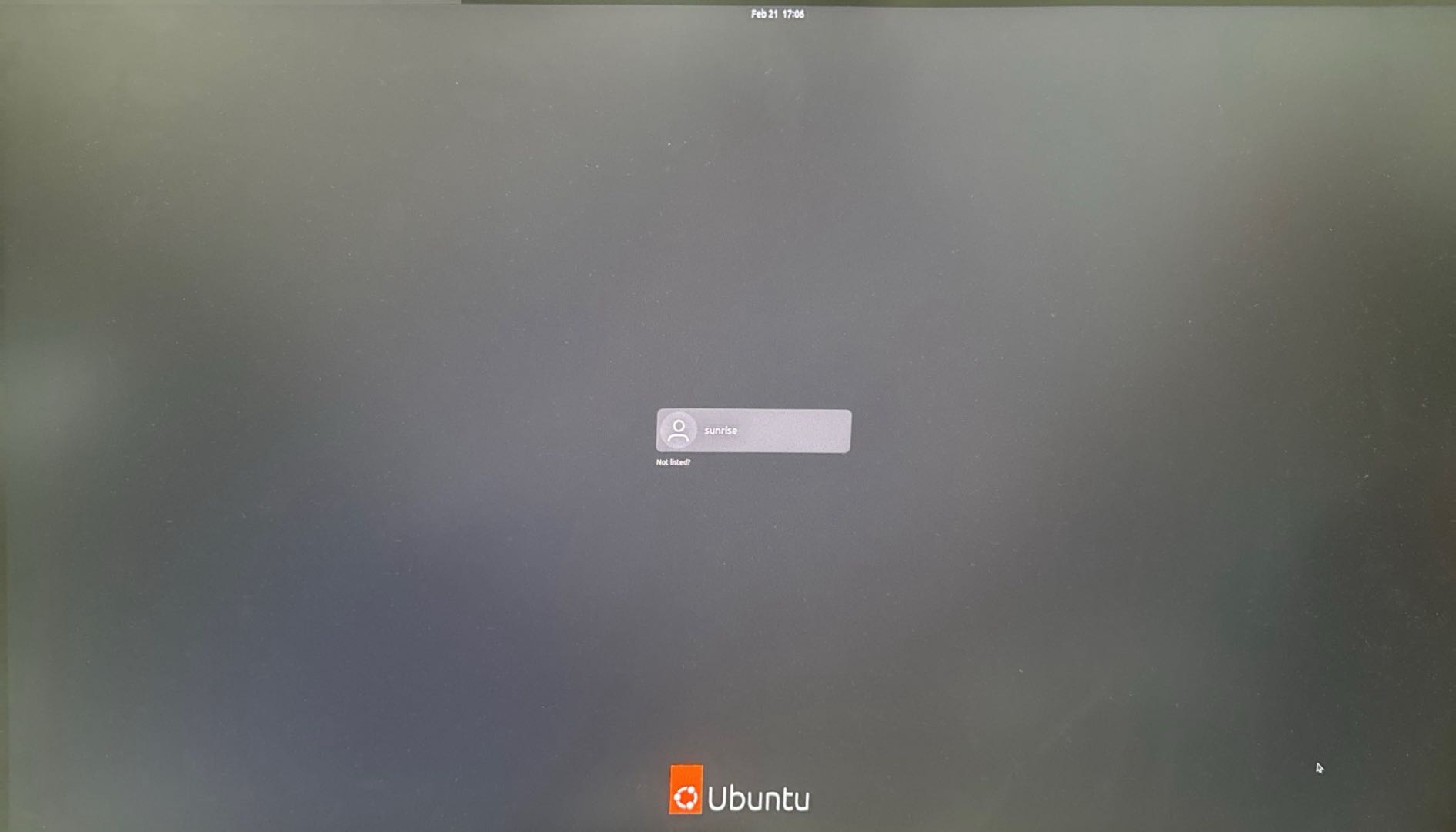
First, keep the development board powered off, connect the development board to the display via HDMI cable, and finally power on the development board.
During the first system startup, default environment configuration will be performed. The entire process takes about 45 seconds. After configuration is complete, the Ubuntu system desktop will be output to the display.
Development Board Indicator Description
- Green indicator: Lighting indicates hardware power supply is normal
If there is no display output for a long time after powering on the development board (more than 2 minutes), the development board has a startup issue. It is necessary to debug via serial cable to check if the development board is functioning normally.
After the Ubuntu Desktop version system starts up, the system desktop will be output to the display via the Display transmission interface, as shown in the figure below: