OpenPose (Human Keypoint Detection)
1. Introduction
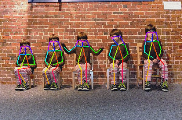
OpenPose is a real-time multi-person pose estimation system developed by the Robotics Institute team at Carnegie Mellon University (CMU). It is an important breakthrough in the field of computer vision for human pose recognition. It can simultaneously detect multiple human key nodes (such as joints, facial feature points, hand keypoints, etc.) from a single image or video, and construct human skeletal connection structures, providing powerful technical support for fields such as motion analysis, human-computer interaction, and virtual reality.
Project Directory
OPENPOSE
├─cpp
│  ├─dependencies	##C++ example dependencies
│  │  ├─include
│  │  │      bmnn_utils.h
│  │  │      bm_wrapper.hpp
│  │  │      ff_decode.hpp
│  │  │      json.hpp
│  │  │      utils.hpp
│  │  │
│  │  └─src
│  │          ff_decode.cpp
│  │
│  └─openpose_bmcv	##bmcv C++ example
│          CMakeLists.txt
│          main.cpp
│          openpose.cpp
│          openpose.hpp
│          openpose_bmcv.soc
│          pose_postprocess.cpp
│          pose_postprocess.hpp
│
├─datasets	##Dataset storage
│
├─docs		##Help documentation
│
├─models	##1684X models
│  └─BM1684X
│          pose_body_25_fp32_1b.bmodel
│          pose_coco_fp16_1b.bmodel
│          pose_coco_fp32_1b.bmodel
│          pose_coco_int8_1b.bmodel
│          pose_coco_int8_4b.bmodel
│
├─python	##Python examples
│      openpose_opencv.py
│      requirements.txt
│
├─tools		##Testing and comparison tools
│      compare_statis.py
│      eval_coco.py
│
└─tpu_kernel_module		##Library used for TPU acceleration in C++ examples
        libbm1684x_kernel_module.so
2. Running Steps
1. Python Examples
1.1 Configure Python Environment
opencv Environment (for running openpose_opencv.py)
pip3 install -r python/requirements.txt -i https://pypi.tuna.tsinghua.edu.cn/simple1.2 Inference Testing
File Parameter Description
Parameters for openpose_opencv.py are as follows:
usage: openpose_opencv.py [--input INPUT] [--bmodel BMODEL] [--dev_id DEV_ID]

--input: Test data path, can input the path of the entire image folder or video path;
--bmodel: bmodel path for inference, default uses stage 0 network for inference;
--dev_id: TPU device id for inference.
Image Testing
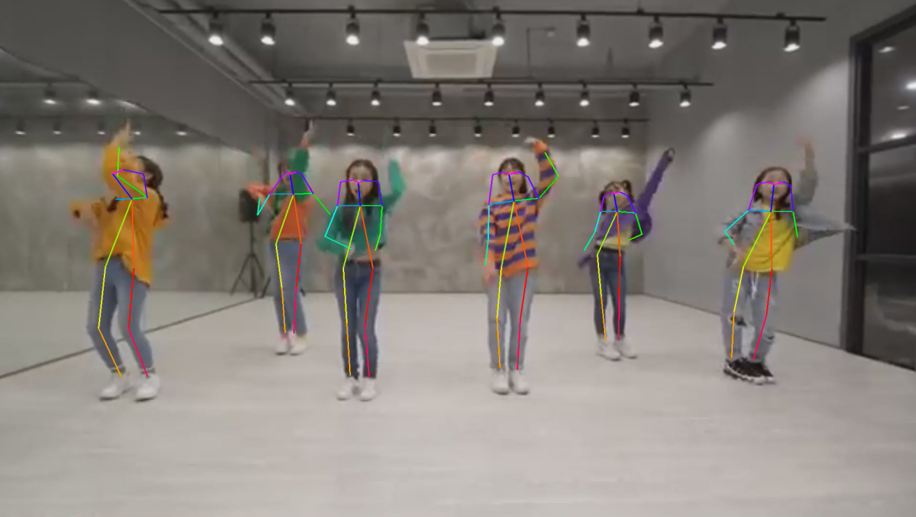
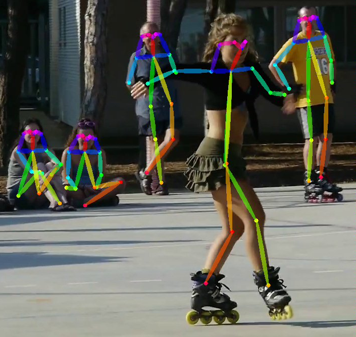
Image testing example is as follows. Supports testing the entire image folder.
python3 python/openpose_opencv.py --input datasets/test --bmodel models/BM1684X/pose_coco_fp32_1b.bmodel --dev_id 0After testing, predicted images will be saved in results/images, predicted keypoint coordinates will be saved in results/pose_coco_fp32_1b.bmodel_test_opencv_python_result.json, and predicted results, inference time and other information will be printed. Output is as follows:
Video Testing
Video testing example is as follows. Supports testing on video streams.
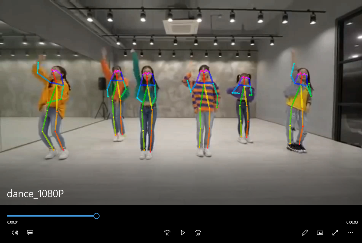
python3 python/openpose_opencv.py --input datasets/dance_1080P.mp4 --bmodel models/BM1684X/pose_coco_fp32_1b.bmodel --dev_id 0After testing, predicted results will be drawn in results/dance_1080P.avi, and predicted results, inference time and other information will be printed. Video testing takes longer to get results, please be patient.
2. C++ Examples
1. Cross-compilation Environment Setup
C++ programs need to compile dependency files to run on the board. To save pressure on edge devices, we choose to use an X86 Linux environment for cross-compilation.
Setting up cross-compilation environment, two methods provided:
(1) Install cross-compilation toolchain via apt:
If your system and target SoC platform have the same libc version (can be queried via ldd --version command), you can install using the following command:
sudo apt-get install gcc-aarch64-linux-gnu g++-aarch64-linux-gnuUninstall method:
sudo apt remove cpp-*-aarch64-linux-gnuIf your environment does not meet the above requirements, it is recommended to use method (2).
(2) Set up cross-compilation environment via docker:
You can use the provided docker image -- stream_dev.tar as the cross-compilation environment.
If using Docker for the first time, execute the following commands to install and configure (only required for first time):
sudo apt install docker.io
sudo systemctl start docker
sudo systemctl enable docker
sudo groupadd docker
sudo usermod -aG docker $USER
newgrp docker
Load the image in the downloaded image directory
docker load -i stream_dev.tarYou can view loaded images via docker images, default is stream_dev:latest
Create container
docker run --privileged --name stream_dev -v $PWD:/workspace  -it stream_dev:latest
# stream_dev is just an example name, please specify your own container name
The workspace directory in the container will mount to the host directory where you run docker run. You can compile projects in this container. The workspace directory is under root, changes in this directory will map to changes in corresponding files in the local directory.
Note: When creating a container, you need to go to the parent directory of soc-sdk (dependency compilation environment) and above
1.2 Package Dependency Files
Package libsophon
Extract
libsophon_soc_x.y.z_aarch64.tar.gz, where x.y.z is the version number.# Create root directory for dependency files mkdir -p soc-sdk # Extract libsophon_soc_x.y.z_aarch64.tar.gz tar -zxf libsophon_soc_${x.y.z}_aarch64.tar.gz # Copy related library directories and header file directories to the dependency root directory cp -rf libsophon_soc_${x.y.z}_aarch64/opt/sophon/libsophon-${x.y.z}/lib soc-sdk cp -rf libsophon_soc_${x.y.z}_aarch64/opt/sophon/libsophon-${x.y.z}/include soc-sdkPackage sophon-ffmpeg and sophon-opencv
Extract
sophon-mw-soc_x.y.z_aarch64.tar.gz, where x.y.z is the version number.# Extract sophon-mw-soc_x.y.z_aarch64.tar.gz tar -zxf sophon-mw-soc_${x.y.z}_aarch64.tar.gz # Copy ffmpeg and opencv library directories and header file directories to soc-sdk directory cp -rf sophon-mw-soc_${x.y.z}_aarch64/opt/sophon/sophon-ffmpeg_${x.y.z}/lib soc-sdk cp -rf sophon-mw-soc_${x.y.z}_aarch64/opt/sophon/sophon-ffmpeg_${x.y.z}/include soc-sdk cp -rf sophon-mw-soc_${x.y.z}_aarch64/opt/sophon/sophon-opencv_${x.y.z}/lib soc-sdk cp -rf sophon-mw-soc_${x.y.z}_aarch64/opt/sophon/sophon-opencv_${x.y.z}/include soc-sdk
1.3 Perform Cross-compilation
After setting up the cross-compilation environment, use the cross-compilation toolchain to compile and generate executable files. OpenPose_opencv and openpose_bmcv have the same compilation method. Taking compiling the openpose_opencv program as an example:
cd cpp/openpose_opencv
mkdir build && cd build
#Please modify -DSDK path according to actual situation, use absolute path.
cmake -DTARGET_ARCH=soc -DSDK=/workspace/soc-sdk/ ..
make
After compilation completes, a .soc file will be generated in the corresponding directory, for example: cpp/openpose_opencv/openpose_opencv.soc. This file is also provided and can be used directly.
2. Inference Testing
You need to copy the executable files generated from cross-compilation and required models and test data to the SoC platform (i.e., BM1684X development board) for testing.
Parameter Description
The executable program has a default set of parameters. Please pass parameters according to actual situation. openpose_bmcv.soc specific parameters are as follows:
Usage: openpose_bmcv.soc [params]

        --bmodel (value:../../models/BM1684/pose_coco_fp32_1b.bmodel)
                bmodel file path
        --dev_id (value:0)
                TPU device id
        --help (value:true)
                print help information.
        --input (value:../../datasets/test)
                input path, images direction or video file path
        --performance_opt (value:no_opt)
                performance optimization type, supporting [tpu_kernel_opt, tpu_kernel_half_img_size_opt, cpu_opt, no_opt]
Image Testing
Image testing example is as follows. Supports testing the entire image folder.
##First add executable permission to the file
chmod +x openpose_bmcv.soc
./openpose_bmcv.soc --input=../../datasets/test --bmodel=../../models/BM1684X/pose_coco_fp32_1b.bmodel --dev_id=0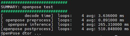
Only on BM1684X, if you need to use tpu_kernel post-processing for acceleration, you can use the following command.
./openpose_bmcv.soc --input=../../datasets/test --bmodel=../../models/BM1684X/pose_coco_fp32_1b.bmodel --dev_id=0 --performance_opt=tpu_kernel_opt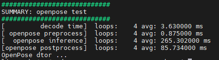
Furthermore, if you only upscale the output feature map to half of the original image in post-processing, accuracy will slightly decrease while performance will significantly improve. Use the following command.
./openpose_bmcv.soc --input=../../datasets/test --bmodel=../../models/BM1684X/pose_coco_fp32_1b.bmodel --dev_id=0 --performance_opt=tpu_kernel_half_img_size_opt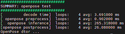
If you need to use algorithmic post-processing performance optimization for acceleration, with a slight accuracy decrease, use the following command.
./openpose_bmcv.soc --input=../../datasets/test --bmodel=../../models/BM1684X/pose_coco_fp32_1b.bmodel --dev_id=0 --performance_opt=cpu_opt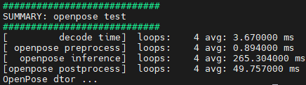
After testing, predicted images will be saved in results/images, predicted keypoint coordinates will be saved in results/pose_coco_fp32_1b.bmodel.bmodel_test_bmcv_cpp_result.json, and predicted results, inference time and other information will be printed.
Video Testing
Video testing example is as follows. Supports testing on video streams. On BM1684X, the post-processing acceleration command is similar to image testing. If using algorithmic post-processing acceleration, it is also similar to image testing.
./openpose_bmcv.soc --input=../../datasets/dance_1080P.mp4 --bmodel=../../models/BM1684X/pose_coco_fp32_1b.bmodel --dev_id=0After testing, predicted results will be drawn on images and saved in results/images, and predicted results, inference time and other information will be printed.