08 Serial Port
1 Serial Port Interface Overview
GM-3568JHF development board is designed based on Rockchip RK3568J chip, providing rich serial port interfaces, supporting various serial communication protocols and application scenarios. The serial port is one of the most commonly used communication interfaces in embedded systems, widely used in device debugging, data transmission, industrial control, etc.
1.1 Serial Port Interface Configuration
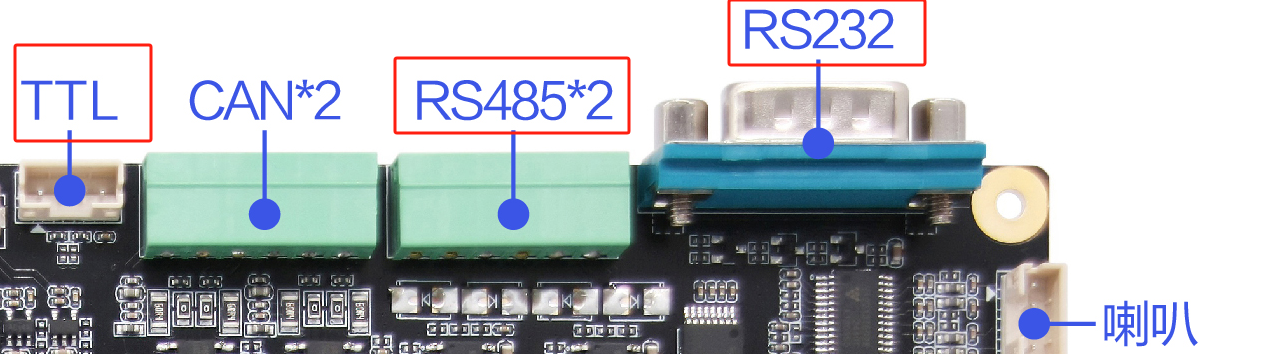
There are a total of 6 serial ports from RK3568J on the development board:
| Serial Type | Quantity | Interface Form | Electrical Standard | Application Scenario |
|---|---|---|---|---|
| RS232 | 1 | DB9 Connector | RS232 Level | Industrial device communication |
| RS485 | 2 | Terminal Interface | RS485 Differential | Industrial bus communication |
| TTL | 2 | Pin Header Interface | 3.3V TTL | Debugging, sensor communication |
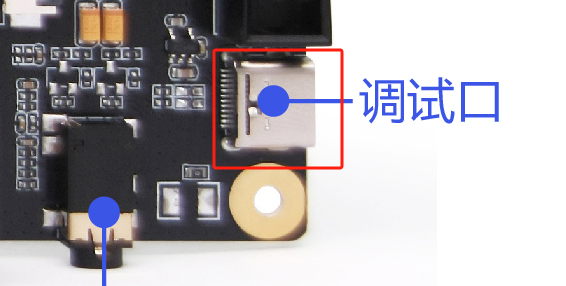
| TypeC Debug | 1 | Type-C Interface | USB to TTL | System debugging |
1.2 Serial Port Electrical Standard Introduction
RS232 Standard
- Voltage Range: ±3V to ±15V
- Logic Level: Positive voltage represents logic 0, negative voltage represents logic 1
- Transmission Distance: Max 15 meters (9600bps)
- Connection Method: Single-ended signal transmission
- Anti-interference: Average anti-interference ability
RS485 Standard
- Voltage Range: ±1.5V to ±6V
- Logic Level: Differential signal transmission
- Transmission Distance: Max 1200 meters (9600bps)
- Connection Method: Two-wire differential transmission (A+, 😎
- Anti-interference: Strong anti-interference ability, suitable for industrial environments
TTL Standard
Voltage Range: 0V to 3.3V
Logic Level: High level 3.3V, low level 0V
Transmission Distance: Generally less than 3 meters
Connection Method: Single-ended signal transmission
Application: Mainly used for board-level communication and debugging
RS232: 1
RS485: 2
TTL: 2 (One of them is on the 40PIN interface, which can be used as RS485 with Raspberry Pi expansion board)
- TypeC(Debug): 1 (This interface is a USB to TTL interface, can be used directly after connecting TypeC)
2 Connecting Serial Port
Different interfaces correspond to different connection methods. The following are the connection methods for different serial ports.
2.1 TTL
Take USB to TTL tool as an example:
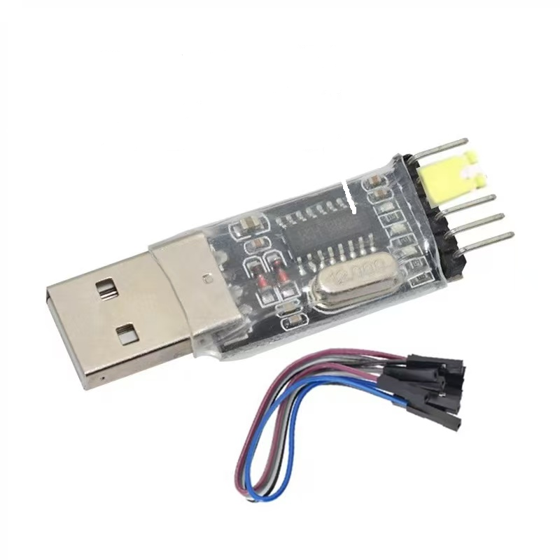
- TXD -- RXD
- RXD -- TXD
- GND -- GND
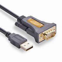
2.2 RS232
Take USB to 232 tool as an example:
Because it is a standard 232 interface, it can be connected directly.
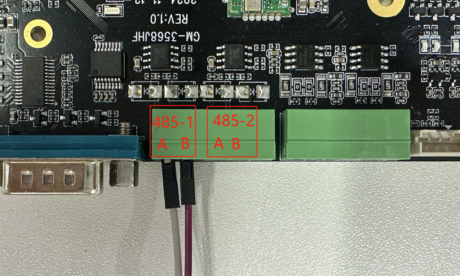
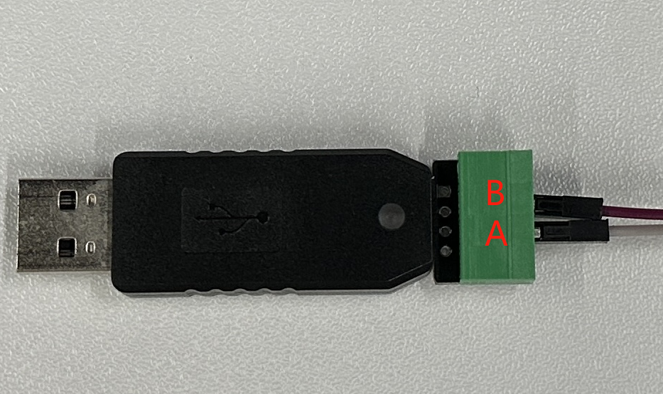
2.3 RS485
Take USB to 485 tool as an example:
USB to 485-A -> Development Board-A
USB to 485-B -> Development Board-B
As shown in the figure:
2.4 Serial Communication Test
Use the TTL serial port on the board for the experiment, the corresponding device file is /dev/ttyS4. Directly reading and writing to the tty device file can control the device to receive or send data through the serial port. Below we use the board with the serial port debugging assistant under Windows.
Tips
RS485 serial port has added automatic direction switching function in the driver layer, communication is the same as ordinary serial port.
Query serial port parameters and modify baud rate
Use stty tool to query serial port parameters
# Execute the following command in the terminal of the development board
root@linaro-alip:/# stty -F /dev/ttyS4
speed 9600 baud; line = 0;
-brkint -imaxbel
Use stty tool to modify serial port parameters
# Set communication rate, where ispeed is input rate, ospeed is output rate
root@linaro-alip:/# stty -F /dev/ttyS4 ispeed 115200 ospeed 115200
root@linaro-alip:/# stty -F /dev/ttyS4
speed 115200 baud; line = 0;
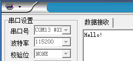
-brkint -imaxbelCommunication with PC
After configuring the serial debugging assistant on the PC side, use the following command on the board side to test sending data through the serial port:
1) Sending Data:
# Execute the following command in the terminal on the board
# Use echo command to write string "Hello!" to the terminal device file
echo Hello! > /dev/ttyS4
The serial debugging assistant on the PC will receive the content.
2) Receiving Data:
To test receiving data, you can use the microcom tool:
# Execute the following command in the terminal on the board
# Use microcom command to read terminal device file, -s parameter can set baud rate
busybox microcom -s 115200 /dev/ttyS4
Hello World! # Data sent from PC
# microcom command will wait
# Use serial debugging assistant to send string
# The terminal on the board will output the received content
3 Troubleshooting
3.1 Serial Port Device Cannot Be Opened
Symptom: Prompt "Permission denied" or device does not exist.
Solution:
# Check if device node exists
ls -l /dev/ttyS*

# Check device permissions
sudo chmod 666 /dev/ttyS4

# Add user to dialout group
sudo usermod -a -G dialout $USER
3.2 Data Transmission Error
Possible Causes:
- Baud rate mismatch
- Data bits, stop bits, parity bits configuration error
- Hardware connection problem
Troubleshooting Steps:
# Check serial port configuration
stty -F /dev/ttyS4 -a

# Set correct serial port parameters
stty -F /dev/ttyS4 115200 cs8 -cstopb -parenb
3.3 RS485 Communication Problem
Precautions:
- Ensure A and B lines are connected correctly
- Check terminal resistance configuration
- Verify ground connection
# RS485 test command
echo "test" > /dev/ttyS1  # Send to RS485 port 1
cat /dev/ttyS2           # Receive from RS485 port 2
3.4 Serial Port Conflict
Solution:
# Check serial port usage
lsof /dev/ttyS*

# Terminate process occupying serial port
sudo fuser -k /dev/ttyS4