05 NAPI Development Practice Demonstration
1. Introduction
In this chapter, I will take GPIO read/write as an example to bring you through a complete analysis of how to create a NAPI project, and explain the project structure and source code in detail. In subsequent usage, we will use this as a basis and will not introduce each peripheral and interface in detail, only providing necessary explanations!
Our application uses the "Native C++" template to implement calling Linux kernel command line interfaces through NAPI (Node-API) to control Rk3568's GPIO on ArkTS.
This chapter is somewhat difficult but very important!
This Chapter Data Path
hap package: /05-Development-Materials/01-OpenHarmony-Development-Materials/Peripheral-Test-APP/HAP/GPIO_TEST.hap
Project source: /05-Development-Materials/01-OpenHarmony-Development-Materials/Peripheral-Test-APP/SRC/GPIO_TEST
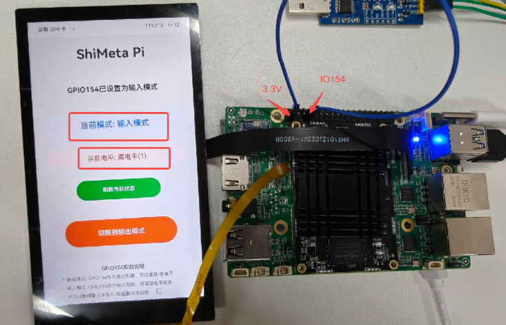
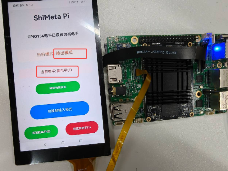
2. Target Effect Image to Achieve
Input mode:
Output mode:
3. Code Structure Interpretation
This article will interpret the core code. The project code structure generated by the software using Native C++ template is as follows:
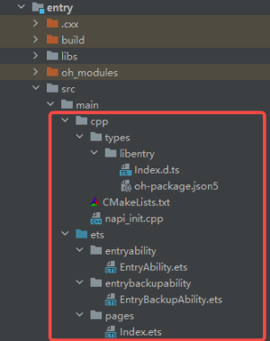
napi_init.cppThis is the core file for NAPI development. The main function interface functions are defined here by users. Additionally, NAPI module registration initialization code is also generated under this file. It implements the bridge between JavaScript and C++, providing hardware control functions.CMakeLists.txtBuild configuration file, defines compilation rules and dependencies for C++ module.Index.etsMain interface page, implements user interface for code control, calls underlying C++ functions through NAPI.EntryAbility.etsDefines application lifecycle management and main window creation.EntryBackupAbility.etsImplements application data backup and restore functions.module.json5Module configuration file.oh-package.json5NAPI module type declaration package configuration file.
4. Index.ets File Calling C/C++ Function Process
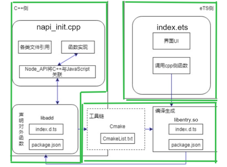
4.1 Application Framework
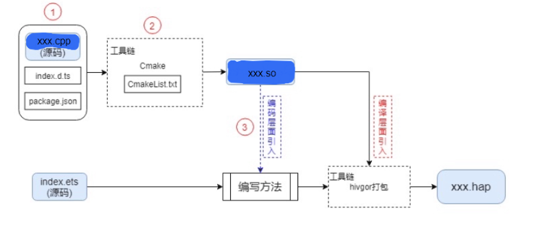
The entire application framework can be simply divided into three parts: C++ side, eTS side, and various toolchains.
- C++ side: Contains references to various files, C++ or C code, Node_API information linking C++ functions with JavaScript, etc.
- eTS side: Contains UI, its own methods, calls to reference package methods, etc.
- Toolchain: Contains series of tools including Cmake packaging tool.
4.2 Call and Packaging Process
In the process of eTS calling C++ methods, the call and packaging process are as follows:
5. C++ Side Code Implementation
5.1 Function Code Writing & Interpretation
Below are explanations of several main functions in C++:
First, use 2 functions to implement GPIO (General Purpose Input Output) file operation functions.
void write_gpio_file(const char *filename, const char *value) {
    char path[256];
    snprintf(path, sizeof(path), "%s/%s", GPIO_PATH, filename);
    OH_LOG_Print(LOG_APP, LOG_INFO, GLOBAL_RESMGR, GPIO_TAG,
                       " %{public}s,%{public}s", GPIO_PATH, filename);
    int fd = open(path, O_WRONLY);
    if (fd < 0) {
        OH_LOG_Print(LOG_APP, LOG_ERROR, GLOBAL_RESMGR, GPIO_TAG,
                       " open failed for path:%{public}s, errno:%{public}d, error:%{public}s",
                       path, errno, strerror(errno));
        exit(1);
    }

    if (write(fd, value, strlen(value)) < 0) {
        OH_LOG_Print(LOG_APP, LOG_ERROR, GLOBAL_RESMGR, GPIO_TAG,
                       " open failed for path:%{public}s, errno:%{public}d, error:%{public}s",
                       path, errno, strerror(errno));
        close(fd);
        exit(1);
    }
    close(fd);
}
First, explain the write_gpio_file function. The implemented function is to write a value to the specified GPIO file, used to control GPIO pin state.
Implementation details:
1- Use snprintf to safely construct the complete file path, save the path to path.
2- Open the GPIO file in write-only mode using open. After successfully opening the file, use write to write the target value.
Tip
When errors occur, print logs through OH_LOG_Print for easy troubleshooting.
char* read_gpio_file(const char *filename) {
    char path[256];
    snprintf(path, sizeof(path), "%s/%s", GPIO_PATH, filename);
    OH_LOG_Print(LOG_APP, LOG_INFO, GLOBAL_RESMGR, GPIO_TAG,
                       " reading %{public}s,%{public}s", GPIO_PATH, filename);
    int fd = open(path, O_RDONLY);
    if (fd < 0) {
        OH_LOG_Print(LOG_APP, LOG_ERROR, GLOBAL_RESMGR, GPIO_TAG,
                       " open failed for path:%{public}s, errno:%{public}d, error:%{public}s",
                       path, errno, strerror(errno));
        return nullptr;
    }

    char* buffer = (char*)malloc(32);
    ssize_t bytes_read = read(fd, buffer, 31);
    if (bytes_read < 0) {
        OH_LOG_Print(LOG_APP, LOG_ERROR, GLOBAL_RESMGR, GPIO_TAG,
                       " read failed for path:%{public}s, errno:%{public}d, error:%{public}s",
                       path, errno, strerror(errno));
        close(fd);
        free(buffer);
        return nullptr;
    }

    buffer[bytes_read] = '\0';
    // Remove newline character
    if (bytes_read > 0 && buffer[bytes_read - 1] == '\n') {
        buffer[bytes_read - 1] = '\0';
    }

    close(fd);
    return buffer;
}
Now explain the read_gpio_file function. The implemented function is to read the value from the specified GPIO file, used to obtain GPIO pin state. On success, it returns a dynamically allocated memory pointer. On failure, it returns nullptr.
Implementation details:
1- Use snprintf to safely construct the complete file path, save the path to path.
2- Open the GPIO file in read-only mode using open.
3- Use malloc function to dynamically allocate 32-byte buffer, use read to read the string from the opened file and save to the applied buffer.
4- Return the read value after removing the newline character.
After implementing the above two parts, we can implement file read/write to control the target peripheral. Let's look at specific control function:
// Set GPIO direction
static napi_value SetGpioDirection(napi_env env, napi_callback_info info)
{
    size_t argc = 1;
    napi_value args[1];
    napi_get_cb_info(env, info, &argc, args, nullptr, nullptr);

    if (argc < 1) {
        napi_throw_error(env, nullptr, "Expected 1 argument: direction value (in/out)");
        return nullptr;
    }

    size_t str_size;
    napi_get_value_string_utf8(env, args[0], nullptr, 0, &str_size);
    char* direction_value = (char*)malloc(str_size + 1);
    napi_get_value_string_utf8(env, args[0], direction_value, str_size + 1, &str_size);

    write_gpio_file("direction", direction_value);
    free(direction_value);

    napi_value result;
    napi_get_boolean(env, true, &result);
    return result;
}
First is the NAPI function: SetGpioDirection. The function is to set the working direction of GPIO pin (input mode "in" or output mode "out").
First explain the parameters passed to the function:
env NAPI environment context, used for all NAPI calls.
info Callback information, contains parameters passed from JavaScript.
Now analyze the function body:
1- argc represents the number of parameters passed. The args array is used to save the passed parameter values. The function napi_get_cb_info can obtain parameter information passed from JavaScript call, such as the direction "in".
2- First use the function napi_get_value_string_utf8 without providing buffer, only get the length of the passed string by calling the function and save to str_size. After obtaining the target string length, dynamically allocate memory. Use the function napi_get_value_string_utf8 again to extract the target length string value from JavaScript parameters and convert to C string, save to the allocated buffer.
3- Call the previously defined write_gpio_file function to write the direction parameter to the target folder, then free the memory.
4- After successful write, create JavaScript boolean value through napi_get_boolean, save to result and return.
The previous function implements the function of sending commands. Let's analyze a function that reads return value to obtain IO direction:
// Read GPIO direction
static napi_value GetGpioDirection(napi_env env, napi_callback_info info)
{
    char* direction_value = read_gpio_file("direction");
    if (direction_value == nullptr) {
        napi_throw_error(env, nullptr, "Failed to read GPIO direction");
        return nullptr;
    }

    napi_value result;
    napi_create_string_utf8(env, direction_value, NAPI_AUTO_LENGTH, &result);
    free(direction_value);

    return result;
}
The function GetGpioDirection implements the function of reading the current working direction of GPIO pin.
The parameters and return values are the same as other NAPI functions. We only need to care about the function body:
1- First call the previously defined function read_gpio_file to read the direction value of the corresponding IO in the specified folder.
2- Then use the function napi_create_string_utf8 to convert the read C string to JavaScript string, and save the result to result for return (using parameter NAPI_AUTO_LENGTH can automatically calculate string length).
In addition, we also defined functions for setting GPIO level value and reading GPIO level value. The principle is the same as above, so we won't repeat it. Here is the code:
// Set GPIO level value
static napi_value SetGpioValue(napi_env env, napi_callback_info info)
{
    size_t argc = 1;
    napi_value args[1];
    napi_get_cb_info(env, info, &argc, args, nullptr, nullptr);

    if (argc < 1) {
        napi_throw_error(env, nullptr, "Expected 1 argument: value (0/1)");
        return nullptr;
    }

    size_t str_size;
    napi_get_value_string_utf8(env, args[0], nullptr, 0, &str_size);
    char* value = (char*)malloc(str_size + 1);
    napi_get_value_string_utf8(env, args[0], value, str_size + 1, &str_size);

    write_gpio_file("value", value);
    free(value);

    napi_value result;
    napi_get_boolean(env, true, &result);
    return result;
};

// Read GPIO level value
static napi_value GetGpioValue(napi_env env, napi_callback_info info)
{
    char* value = read_gpio_file("value");
    if (value == nullptr) {
        napi_throw_error(env, nullptr, "Failed to read GPIO value");
        return nullptr;
    }

    napi_value result;
    napi_create_string_utf8(env, value, NAPI_AUTO_LENGTH, &result);
    free(value);

    return result;
};
5.2 Register Module
Let's go to the end of napi_init.cpp function to write the registered function module.
The module registration writing is fixed. In the Init function, in napi_property_descriptor desc[], we need to supplement the part that associates the implemented function in the project with the exposed interface.
EXTERN_C_START
static napi_value Init(napi_env env, napi_value exports)
{
    napi_property_descriptor desc[] = {
        { "setGpioDirection", nullptr, SetGpioDirection, nullptr, nullptr, nullptr, napi_default, nullptr },
        { "getGpioDirection", nullptr, GetGpioDirection, nullptr, nullptr, nullptr, napi_default, nullptr },
        { "setGpioValue", nullptr, SetGpioValue, nullptr, nullptr, nullptr, napi_default, nullptr },
        { "getGpioValue", nullptr, GetGpioValue, nullptr, nullptr, nullptr, napi_default, nullptr },
        { "exportGpio", nullptr, ExportGpio, nullptr, nullptr, nullptr, napi_default, nullptr },
        { "unexportGpio", nullptr, UnexportGpio, nullptr, nullptr, nullptr, napi_default, nullptr }
    };
    napi_define_properties(env, exports, sizeof(desc) / sizeof(desc[0]), desc);
    return exports;
}
EXTERN_C_END
napi_module is used to describe module information. Generally, the only thing that needs to be modified is the module name nm_modname, then register it.
static napi_module demoModule = {
    .nm_version = 1,
    .nm_flags = 0,
    .nm_filename = nullptr,
    .nm_register_func = Init,
    .nm_modname = "entry",
    .nm_priv = ((void*)0),
    .reserved = { 0 },
};

extern "C" __attribute__((constructor)) void RegisterEntryModule(void)
{
    napi_module_register(&demoModule);
}
6. Interface Code Implementation
We need to define the external interface methods and simple descriptions in the Index.d.ts file:
export const setGpioDirection: (direction: string) => boolean
export const getGpioDirection: () => string
export const setGpioValue: (value: string) => boolean
export const getGpioValue: () => string
export const exportGpio: () => boolean
export const unexportGpio: () => boolean
The interface names here are consistent with the interface names provided externally when registering the module.
The content after ":" is the parameter that needs to be passed, and after "=>" is the return value, here it returns JavaScript's boolean type.
Next is to configure CMake packaging parameters in CMakeLists.txt:
# the minimum version of CMake.
cmake_minimum_required(VERSION 3.5.0)
project(GPIO)

set(NATIVERENDER_ROOT_PATH ${CMAKE_CURRENT_SOURCE_DIR})

if(DEFINED PACKAGE_FIND_FILE)
    include(${PACKAGE_FIND_FILE})
endif()

include_directories(${NATIVERENDER_ROOT_PATH}
                    ${NATIVERENDER_ROOT_PATH}/include)

add_library(entry SHARED napi_init.cpp)
target_link_libraries(entry PUBLIC
        libace_napi.z.so
        libhilog_ndk.z.so)
The CMakeLists file basically doesn't need modification. Generally, you just add an extra system library. For example, I just added a libhilog_ndk.z.so library at the end.
7. ETS Side Code Implementation
After all the introduction, it is to call related function functions here.
First, import the NAPI module we defined at the beginning of the file:
import testNapi from 'libentry.so'Then define the struct components used in this example. @State is a reactive state variable. When data changes, the UI interface will automatically update. We defined IO direction, level value, title and other content used in this project.
@Entry
@Component
struct Index {
  @State title: string = 'ShiMeta Pi';
  @State currentMode: string = 'out'; // Current GPIO direction mode
  @State currentValue: string = '0'; // Current GPIO level value
  @State message: string = 'GPIO154(IO4_D2) Control';
  private intervalId: number = -1; // Timer ID
Our Index.ets part of the code is mainly divided into 2 parts: function modules and UI modules. The purpose of doing secondary encapsulation on function modules is to improve code readability and facilitate later function updates. It's a good programming habit. Below, let's explain in detail the function modules used in the UI.
7.1 Function Module Details
We selected the following functions for detailed explanation:
// Read current GPIO direction
private getCurrentGpioDirection() {
  try {
    const direction = testNapi.getGpioDirection();
    this.currentMode = direction;
    hilog.info(DOMAIN, 'GPIO', `Current GPIO154 Direction: ${direction}`);
  } catch (error) {
    hilog.error(DOMAIN, 'GPIO', `Failed to read GPIO direction: ${error}`);
  }
}
The function getCurrentGpioDirection implements the function of reading IO direction. It calls the declared C++ function getGpioDirection to read the direction value and updates it to the reactive variable representing the current IO working mode.
// Set GPIO level value
private setGpioValue(value: string) {
  try {
    testNapi.setGpioValue(value);
    this.currentValue = value;
    this.message = `GPIO154 level set to ${value === '1' ? 'High' : 'Low'}`;
    hilog.info(DOMAIN, 'GPIO', `GPIO154 level set to: ${value}`);
  } catch (error) {
    hilog.error(DOMAIN, 'GPIO', `Failed to set GPIO level value: ${error}`);
  }
}
The function setGpioValue implements the function of setting IO output level in output mode. It calls the declared C++ function setGpioValue to write the set value to IO, and updates it to the reactive variable representing the current IO output level state.
// Start timer (read level status every 0.1s in input mode)
private startValuePolling() {
  this.stopValuePolling(); // Stop previous timer first
  this.intervalId = setInterval(() => {
    if (this.currentMode === 'in') {
      this.getCurrentGpioValue();
    }
  }, 100);
}

// Stop timer
private stopValuePolling() {
  if (this.intervalId !== -1) {
    clearInterval(this.intervalId);
    this.intervalId = -1;
  }
}
The functions startValuePolling and stopValuePolling are respectively used to start and stop the timer.
The function setInterval is a built-in JavaScript function. The implemented functions are respectively to periodically execute the callback function (here 100ms). After successful creation, it returns a timer ID. ID being -1 means no timer or timer creation failed.
The corresponding function clearInterval is also a built-in JavaScript function. The implemented function is to clear the timer with the specified ID.
// Read current status when component initializes
aboutToAppear() {
  this.getCurrentGpioDirection();
  this.getCurrentGpioValue();
  // If initial mode is input mode, start timer
  if (this.currentMode === 'in') {
    this.startValuePolling();
  }
}

// Cleanup timer when component destroys
aboutToDisappear() {
  this.stopValuePolling();
}
The functions aboutToAppear and aboutToDisappear are respectively the initialization process when APP starts and the de-initialization process when exiting. The functions called are all explained above.
For other function modules, please refer to the source code. I believe after understanding the above functions, the rest will be easy to understand. So I won't repeat them here.
7.2 UI Interface Function Details
build() {
  Row() {
    Column({ space: 40 }) {

      Text(this.title)
        .fontSize(40)
        .fontWeight(FontWeight.Bold)
        .margin({ bottom: 30 })
        .textAlign(TextAlign.Center)

      Text(this.message)
        .fontSize(22)
        .fontWeight(FontWeight.Bold)
        .margin({ bottom: 20 })
        .textAlign(TextAlign.Center)

      // Current mode display label
      Text(`Current Mode: ${this.currentMode === 'out' ? 'Output Mode' : 'Input Mode'}`)
        .fontSize(24)
        .fontColor(this.currentMode === 'out' ? '#FF6B35' : '#007DFF')
        .fontWeight(FontWeight.Medium)
        .textAlign(TextAlign.Center)
        .padding(20)
        .backgroundColor(this.currentMode === 'out' ? '#FFF5F0' : '#F0F8FF')
        .borderRadius(10)
        .width('100%')

      // Current level value display label
      Text(`Current Level: ${this.currentValue === '1' ? 'High(1)' : 'Low(0)'}`)
        .fontSize(20)
        .fontColor(this.currentValue === '1' ? '#DC3545' : '#28A745')
        .fontWeight(FontWeight.Medium)
        .textAlign(TextAlign.Center)
        .padding(15)
        .backgroundColor(this.currentValue === '1' ? '#FFF0F0' : '#F0FFF0')
        .borderRadius(8)
        .width('100%')

      // Refresh status button
      Button('Refresh Current Status')
        .width('60%')
        .height(60)
        .fontSize(16)
        .fontWeight(FontWeight.Medium)
        .backgroundColor('#28A745')
        .borderRadius(10)
        .margin({ bottom: 20 })
        .onClick(() => {
          this.getCurrentGpioDirection();
          // Only read level value in input mode
          if (this.currentMode === 'in') {
            this.getCurrentGpioValue();
          }
          this.message = 'Status Refreshed';
        })

      // GPIO direction toggle button
      Button(`Switch to ${this.currentMode === 'out' ? 'Input' : 'Output'} Mode`)
        .width('80%')
        .height(80)
        .fontSize(20)
        .fontWeight(FontWeight.Bold)
        .backgroundColor(this.currentMode === 'out' ? '#007DFF' : '#FF6B35')
        .borderRadius(15)
        .onClick(() => {
          this.toggleGpioDirection();
        })

      // GPIO level value control button group (only displayed in output mode)
      if (this.currentMode === 'out') {
        Row({ space: 20 }) {
          Button('Set Low(0)')
            .width('45%')
            .height(70)
            .fontSize(16)
            .fontWeight(FontWeight.Bold)
            .backgroundColor('#28A745')
            .borderRadius(12)
            .onClick(() => {
              this.setGpioValue('0');
            })

          Button('Set High(1)')
            .width('45%')
            .height(70)
            .fontSize(16)
            .fontWeight(FontWeight.Bold)
            .backgroundColor('#DC3545')
            .borderRadius(12)
            .onClick(() => {
              this.setGpioValue('1');
            })
        }
        .width('100%')
        .justifyContent(FlexAlign.SpaceBetween)
      }

      // Explanatory text
      Column({ space: 10 }) {
        Text('GPIO154 Control Instructions:')
          .fontSize(16)
          .fontWeight(FontWeight.Medium)
          .fontColor('#333333')

        Text('• Output Mode: GPIO154 as output pin, can set High/Low level')
          .fontSize(14)
          .fontColor('#666666')
          .textAlign(TextAlign.Start)
          .width('100%')

        Text('• Input Mode: GPIO154 as input pin, can read level status')
          .fontSize(14)
          .fontColor('#666666')
          .textAlign(TextAlign.Start)
          .width('100%')

        Text('• Click toggle button to switch between Input/Output mode')
          .fontSize(14)
          .fontColor('#666666')
          .textAlign(TextAlign.Start)
          .width('100%')

        Text('• In output mode, click button to set High(1) or Low(0)')
          .fontSize(14)
          .fontColor('#666666')
          .textAlign(TextAlign.Start)
          .width('100%')

        Text('• Click refresh button to read current actual status')
          .fontSize(14)
          .fontColor('#666666')
          .textAlign(TextAlign.Start)
          .width('100%')
      }
      .width('100%')
      .padding(20)
      .backgroundColor('#FAFAFA')
      .borderRadius(10)
    }
    .width('100%')
    .padding(30)
    .justifyContent(FlexAlign.Center)
  }
  .height('100%')
  .backgroundColor('#F5F5F5')
}
After studying "ArkTS Getting Started" in the previous chapter, the above code is clear. It's just putting some button and text label components in horizontal and vertical linear layouts, adding some attributes below the components like size, background color, and click events.
The function modules we use in click events are the ones we implemented through NAPI.
8. Code Compilation, Burning & Program Running
After completing the above code writing, after successfully connecting the device, you can use one-click compilation download and run our program in DevEco Studio:
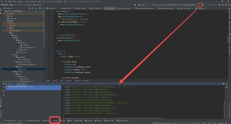
Wait for compilation to complete. Through the development board screen, you can find it automatically enters the program:
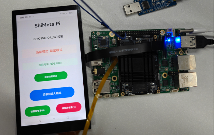
Next, we click the "Switch to Input Mode" button.
Unexpectedly, it should flash back to the desktop, because we haven't exported the directory in the board's terminal yet and added executable permissions to the exported directory. First, enter the development board terminal through HDC, and enter commands in order:
echo 154 > /sys/class/gpio/export
chmod 777 /sys/class/gpio/gpio154/*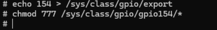
At this point, we can use the program normally.
Below is the explanation of the reason:
The command echo 154 > /sys/class/gpio/export means exporting the corresponding IO154 in the gpio directory. At this time, the kernel will create a folder belonging to IO154. Our subsequent operations are on this folder.
The command chmod 777 /sys/class/gpio/gpio154/* is to add permissions to the exported file gpio154. chmod means permission setting. According to file permission representation under Linux kernel, 7=4+2+1: read(4) + write(2) + execute(1) = full permissions. Among them, 777: owner(7) + group user(7) + other users(7) = all users full permissions. The trailing * is a wildcard, representing all files under that directory.
The Linux system default GPIO file permission is 644. The application is not executed as root user, so it doesn't have write permission and cannot execute corresponding commands. However, the OpenHarmony terminal runs as root by default, so it can modify the default file permissions in the terminal.
Tip
Setting permission 777 here is for convenient debugging. In general production environments, it might be set to 664 to prevent program from being tampered with by other users.
Some friends must ask, why not use the command chmod 777 /sys/class/gpio/*, so that we can export in the NAPI program? That's indeed the case. However, after using the command to export, the gpio154 file is not set to 777 permission, because the chmod command only modifies permissions of existing directories. After exporting in the software, we need to go back to the terminal to add 777 permission to the exported gpio154 for the program to run normally. For convenience, we didn't do much. We also provided IO export and unexport interfaces in napi_init.cpp and Index.d.ts programs. You can try adding these interfaces in the Index.ets program yourself.
Friends can use multimeter and DuPont lines to test the program. The author has tested it, but due to limited space and considering there will be a dedicated chapter on GPIO later, I won't demonstrate here.
9. Summary
This chapter's content is long. It introduced how C++ code is associated with JavaScript through toolchain, how eTS files call interfaces provided by so packages, and through code interpretation, led everyone to learn the specific writing and packaging process of C++ code. It is a very important part of this tutorial's NAPI development tutorial. You can review it against our source code. Friends with ShiMetaPi M4-R1 board can also replicate according to the tutorial.
Through the GPIO read/write example, it fully demonstrated the creation and development process of NAPI project, covering key aspects such as C++ side code implementation, interface definition, CMake configuration, ArkTS interface development, laying a solid foundation for subsequent peripheral interface development.
10: Common NAPI Development Issues
Common Issue 1: System Commands Cannot Modify Permissions
When developing some peripherals, you may encounter situations where system commands cannot modify permissions, causing inability to use normally.
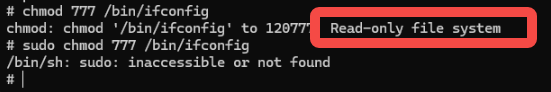
Solution:
# 1. Remount root file system as read-write
mount -o remount,rw /

# 2. Change ifconfig permission
chmod 777 /bin/ifconfig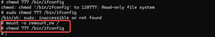
Common Issue 2: ArkTS Does Not Support Implicit Declaration
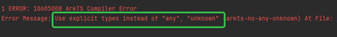
ArkTS requires explicit type declaration (explicit type), cannot use any or unknown type (implicit type).
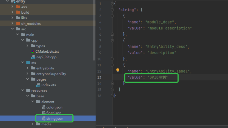
Common Issue 3: Modify Application Name
Common Issue 4: Do I Need to Open Terminal to Set Permissions Every Time Before Development?
In actual projects, we will modify system file permissions through adding system startup scripts, udev rules management permissions, etc. in the system image.
Common Issue 5: APP NAPI Interface Flashes Back When Called (Important!)
Common situation is: clicked a button, its click event called some NAPI interface, but the app flashed back.
Because the software is compiled as 64-bit by default, the development board is 32-bit. If you want to run it on the development board, you need to add a 32-bit compiler, as shown in the figure:
First find the file build-profile.json5 in the entry directory:
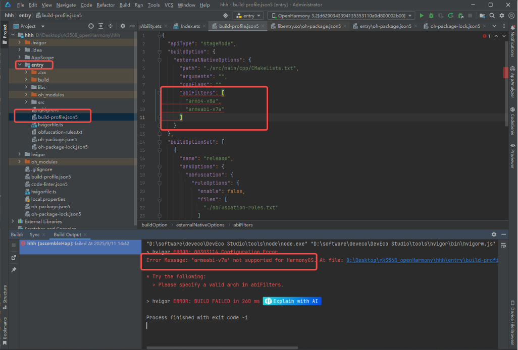
"buildOption": {
    "externalNativeOptions": {
      "path": "./src/main/cpp/CMakeLists.txt",
      "arguments": "",
      "cppFlags": "",
      "abiFilters": [
        "arm64-v8a",
        "armeabi-v7a"
      ]
    }
  }
However, HarmonyOS does not support 32-bit, only OpenHarmony supports the board's 32-bit processor, so it will report an error.
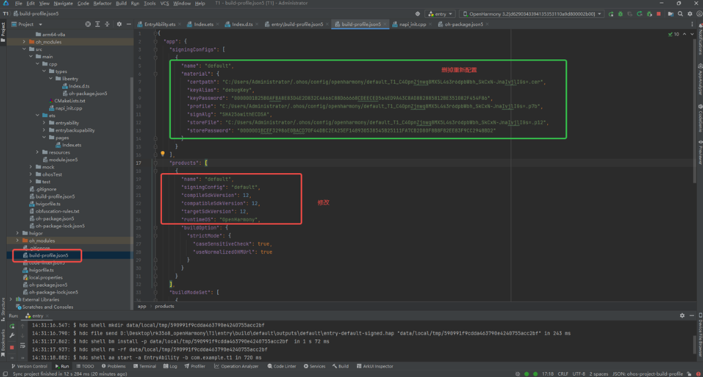
Find the file with the same name build-profile.json5 in the project root directory:
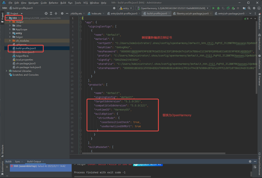
Modify the above content to:
"products": [
  {
    "name": "default",
    "signingConfig": "default",
    "compileSdkVersion": 12,
    "compatibleSdkVersion": 12,
    "targetSdkVersion": 12,
    "runtimeOS": "OpenHarmony",
    "buildOption": {
      "strictMode": {
        "caseSensitiveCheck": true,
        "useNormalizedOHMUrl": true
      }
    }
  }
]
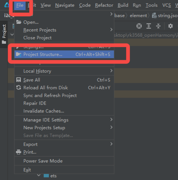
After modification, reconfigure the project structure:
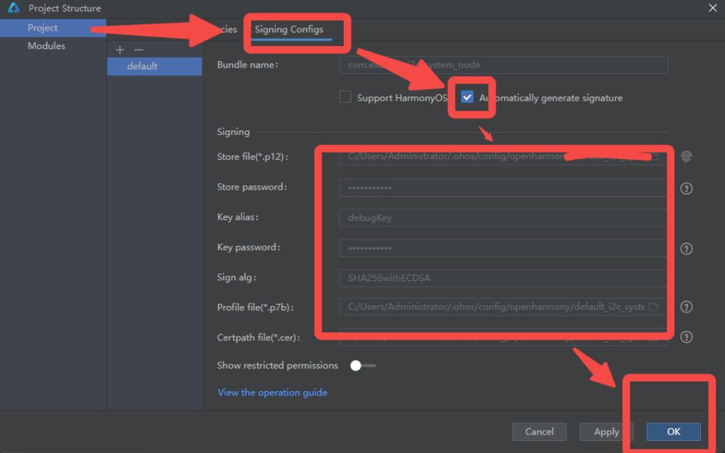
Finally, if there are issues: When in doubt - restart!