12 Screen
1 Introduction to Mainstream Display Interfaces
In embedded devices and consumer electronics products. MIPI DSI, eDP, and HDMI are three mainstream display interfaces used to transmit video data and commands between hosts (such as SoCs, computers, motherboards) and displays (screens).
Each has its own focus and is applied in different fields. Below I will introduce these three display methods in detail.
1.1 MIPI Screen
MIPI (Mobile Industry Processor Interface) is a series of open standards developed by the MIPI Alliance, specifically designed for mobile devices (such as smartphones, tablets, laptops, IoT devices, automotive, etc.), featuring low power consumption, high integration, and strong anti-interference capability.
MIPI interface is not a single interface. The MIPI Alliance primarily customizes standard interfaces and specifications for mobile processors. Developed interfaces are widely used in processors, cameras, displays, baseband modems, and other devices. Common interfaces are MIPI DSI (Display Interface) and MIPI CSI (Camera Interface). This article only introduces MIPI DSI.
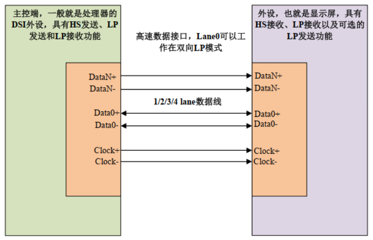
The MIPI DSI interface consists of data lanes and clock lanes, all differential signals. The data lanes can be configured as 1/2/3/4 lanes, and there is one pair of clock lanes, with a maximum of 10 pins. RK3568 uses 4 lanes by default to drive MIPI screens. Of course, for smaller screens, 2 lanes can also be used. For MIPI DSI interfaces, the most commonly used are 2 lanes and 4 lanes.
RK3568 has one MIPI DSI interface, so it also has one MIPI DSI host peripheral for driving MIPI DSI screens. This MIPI DSI HOST kernel complies with the MIPI protocol. MIPI DSI HOST is used to connect the kernel and D-PHY. RK3568's MIPI DSI HOST interface supports 1~4 lanes.
The features supported by RK3568's MIPI DSI HOST controller are as follows:
- Compliant with MIPI Alliance standards
- Supports DPI interface color mapping, with 16/18/24 bit color depth
- All DPI interface signal polarity programmable
- Supports up to 4 Lane D-PHY data lanes
- Data0 supports dual-line communication and Escape mode
- Can transmit all Generic commands
- Supports EOTP packets
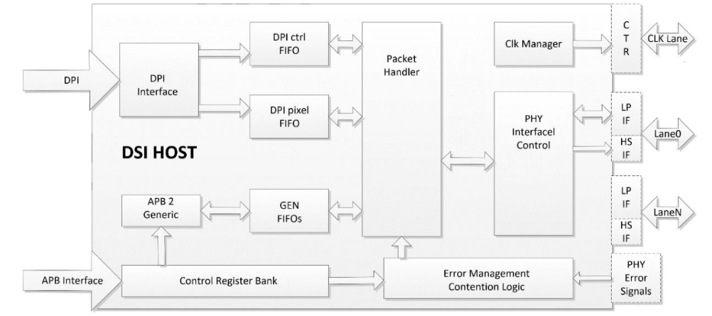
The block diagram of RK3568's MIPI DSI HOST controller is shown in the figure below:
 (For more detailed introduction or questions about the above content, please refer to the official website: https://www.mipi.org/)
 1.2 HDMI Screen
HDMI stands for High Definition Multimedia Interface, which is a pure digital audio and video transmission interface that sends audio and video data simultaneously through a single cable. It is currently widely used in TVs, monitors, computers, set-top boxes, and other fields.
Rockchip's RK3568 chip has a built-in HDMI peripheral interface that can be used to connect HDMI displays. In this chapter, we will learn how to use RK3568's HDMI interface.
The HDMI block diagram is as follows:
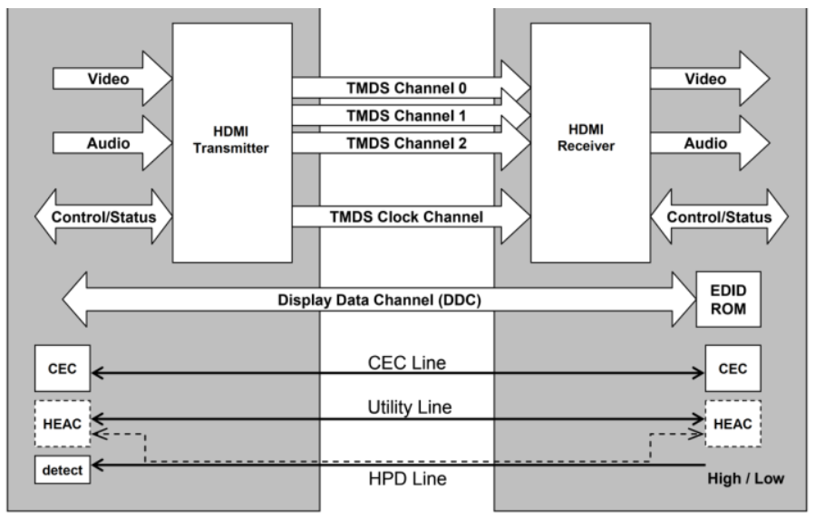
The functions implemented by the several channels in the figure are:
- TMDS: Transmit audio and video data
- CEC: Implement remote control functionality
- DDC: Implement screen resolution adaptation, obtain different screen parameter information through DDC
- HPD: Implement hot-plugging
HDMI has five types of interfaces as follows:
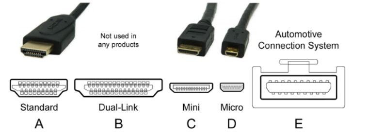
The most commonly used interface type is Type A port. Our M4-R1 development board is also equipped with Type A port.
Below is an introduction to the Type A interface. The corresponding pin diagram and pin definitions are shown in the figures:
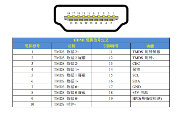
RK3568 has a built-in HDMI TX peripheral that can be used to connect HDMI displays. RK3568's HDMI interface supports versions 1.4a and 2.0a, providing a convenient screen connection method for consumer electronics such as DVD players, camcorders, and cameras. RK3568's HDMI peripheral includes one HDMI transmission controller and one PHY. The features supported by RK3568 HDMI are as follows:
①、Video formats:
- CEA-861-E standard supported video formats, 1080p@60Hz or 720p/1080i@120Hz
- HDMI 1.4b supported video formats:
- CEA-861-E video formats up to 1080p@120Hz
- Supports 4K×2K
- Supports 3D video (TMDS clock up to 340MHz)
- Supports HDMI 2.0 video formats
②、Color support: RGB 4:4:4
③、Pixel clock: 13.5MHz-600MHz
④、Supports up to 192KHz audio sampling rate per IEC60958 standard
⑤、Supports I2C DDC, EDID block read mode
⑥、Supports up to 2160p@60Hz, RGB 4:4:4
(For more detailed introduction or questions about the above content, please refer to the official website: https://www.hdmi.org/)
1.3 eDP Screen
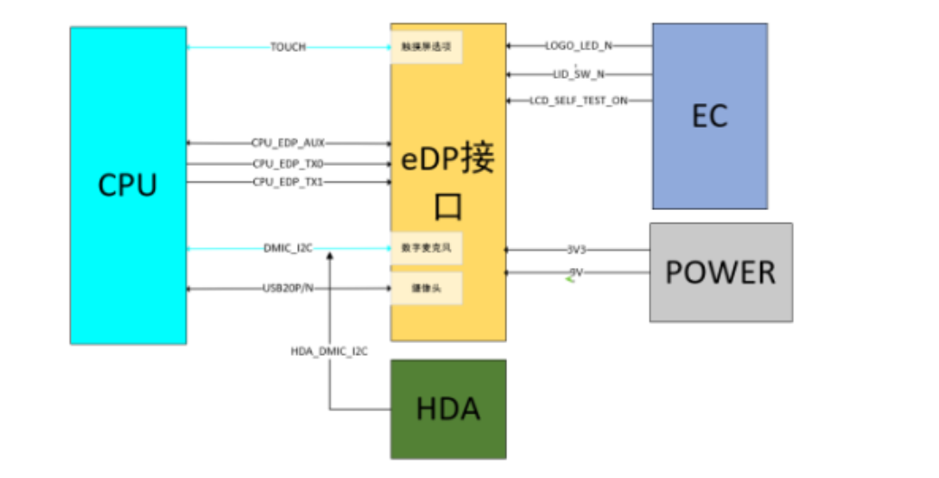
eDP (Embedded DisplayPort) is a digital display interface standard designed specifically for internal connections. It was developed by the Video Electronics Standards Association (VESA) to serve as the main interconnection standard between motherboards and built-in displays in laptops, tablets, all-in-one machines, and other devices. The eDP interface typically uses an FPC interface, connected to the motherboard. Laptops usually use eDP screens, and the screens also have digital microphones and cameras. The screen can also choose touch functionality.
Simply put, eDP is an optimized and extended version of the DisplayPort standard in the embedded field. It inherits the high-performance characteristics of DisplayPort and has been enhanced for the space, power consumption, and cost requirements of embedded devices.
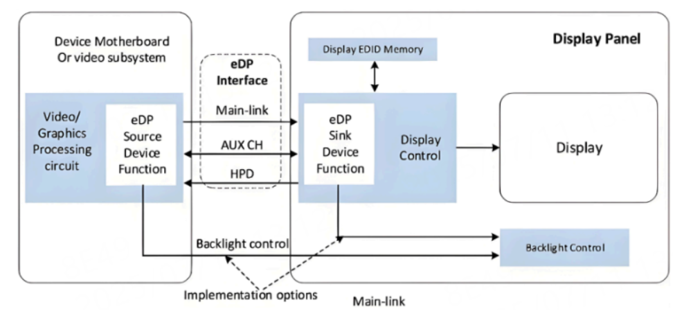
eDP interface composition:
- Main-Link (Main Channel): Used for transmitting video/audio data, composed of high-speed differential pairs (TX0~TX3), up to 4 channels (lanes), but some screens only use 2 lanes
- AUX CH (Auxiliary Channel): Low-speed single-pair differential line (AUX+/-), used for transmitting configuration commands and parameters
- HPD (Hot Plug Detect): Represents the hot-plug detection channel, used to detect HPD signal driven by the Sink end (screen), notifying the Source end whether a device is connected (optional)
The features supported by RK3568 eDP are as follows:
| Feature | Specification |
|---|---|
| Supported Version | eDP 1.3 |
| Maximum Resolution | 2560x1600 @ 60Hz |
| Data Channels (Lanes) | Up to 4 physical channels |
| Color Depth | Supports up to 10bit RGB output |
| Auxiliary Channel (AUX) | Supports AUX CH communication |
| Hot Plug Detect (HPD) | Supports Hot Plug Detect |
| Panel Self Refresh (PSR) | Supports Panel Self Refresh |
(For more detailed introduction or questions about the above content, please refer to the official website: https://www.edp.com/zh-hans/node)
1.4 Summary
The above three display interfaces are currently the most mainstream high-performance screen interfaces. If you need to choose from the three, the biggest difference may be the interface size:
- MIPI DSI Interface: If your device is a small device like a mobile phone screen, the compact MIPI DSI interface is recommended
- eDP Interface: For slightly larger mobile devices like laptops, choose eDP interface screens with moderate size
- HDMI Interface: For desktop computer monitors, TVs, and other fixed large-screen devices for personal use, HDMI, DP and other larger but high-speed interfaces are recommended
2 Three Screen Board Card Interfaces
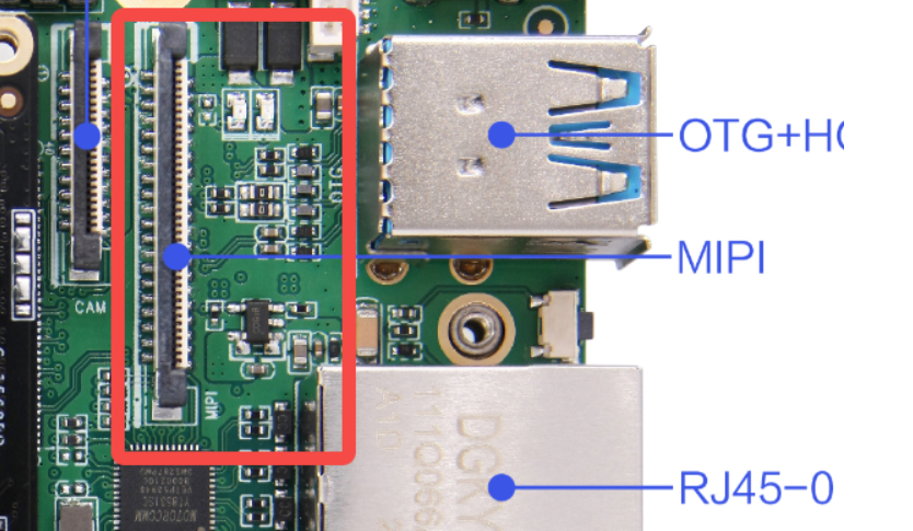
2.1 MIPI DSI Interface
2.2 HDMI Interface
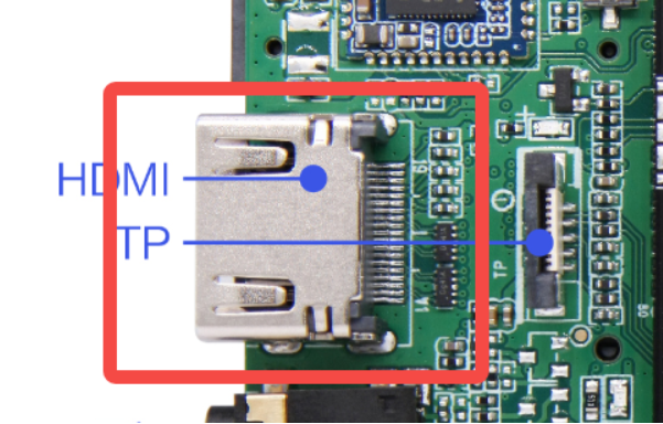
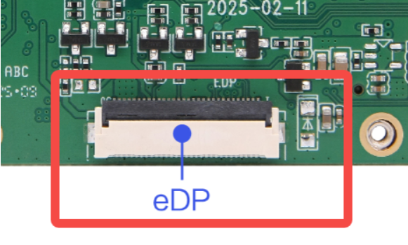
2.3 eDP Interface
3 Screen DTS Configuration and Switching Method Introduction
3.1 Principle Introduction
Since the device trees for RK3568's three screen interfaces (MIPI DSI, HDMI, eDP) are too complex, often one peripheral involves multiple device tree files. Due to space limitations and considering that most friends are beginners, we will only analyze some board-level configuration files in this and subsequent chapters, summarizing some core content for everyone, aiming to help everyone understand these relatively complex peripheral modules. We cannot provide file addresses for everyone.
Before that, let me introduce 2 basic concepts:
1 VOP (Video Output Processor) is RK3568's video output processor, responsible for managing all display outputs. There are three video ports: vp0, vp1, and vp2.
VOP routing determines which video pipeline connects to which display interface. The specific content is as follows:
| Video Port | Routing Configuration | Target Interface |
|---|---|---|
| vp0 | vp0_out_dsi0 | MIPI DSI0 |
| vp0 | vp0_out_dsi1 | MIPI DSI1 |
| vp0 | vp0_out_edp | eDP |
| vp0 | vp0_out_hdmi | HDMI |
| vp1 | vp1_out_dsi0 | MIPI DSI0 |
| vp1 | vp1_out_dsi1 | MIPI DSI1 |
| vp1 | vp1_out_edp | eDP |
| vp1 | vp1_out_hdmi | HDMI |
| vp1 | vp1_out_lvds | LVDS |
| vp2 | vp2_out_lvds | LVDS |
| vp2 | vp2_out_rgb | RGB |
2 PHY (Physical Layer) is the physical layer interface, responsible for converting between digital signals and physical transmission media. Different screen interfaces require different PHY. The specific content is as follows.
| PHY Type | Node Name | Base Address | Function Description |
|---|---|---|---|
| Video PHY | video_phy0 | 0xfe850000 | Used for MIPI DSI interface physical layer signal processing |
| Video PHY | video_phy1 | 0xfe860000 | Used for MIPI DSI interface physical layer signal processing |
| eDP PHY | edp_phy | 0xfdcb0000 | Specifically used for eDP interface physical layer processing |
| HDMI PHY | Built-in PHY | - | HDMI controller has built-in PHY function, configured via rockchip,phy-table for different frequency parameters |
3.2 MIPI DTS Configuration
&dsi0 {
    status = "okay";

    dsi0_panel: panel@0 {
        compatible = "simple-panel-dsi";
        reg = <0>;
        backlight = <&backlight>;
        prepare-delay-ms = <2>;
        reset-delay-ms = <100>;
        init-delay-ms = <20>;
        enable-delay-ms = <120>;
        disable-delay-ms = <50>;
        unprepare-delay-ms = <20>;
        width-mm = <68>;
        height-mm = <121>;

        dsi,flags = <(MIPI_DSI_MODE_VIDEO | MIPI_DSI_MODE_VIDEO_BURST |
                      MIPI_DSI_MODE_LPM | MIPI_DSI_MODE_EOT_PACKET)>;
        dsi,format = <MIPI_DSI_FMT_RGB888>;
        dsi,lanes = <4>;

        pinctrl-names = "default";
        pinctrl-0 = <&mipi_power_en>;
        enable-gpios = <&gpio3 RK_PB6 GPIO_ACTIVE_HIGH>;

        panel-init-sequence = [
            05 64 01 11
            39 00 04 FF 98 81 03
            /* ... more initialization commands ... */
        ];
    };
};

&dsi0_in_vp1 {
    status = "okay";
};

&route_dsi0 {
    status = "okay";
    connect = <&vp1_out_dsi0>;
};- compatible = "simple-panel-dsi" : Generic DSI panel driver
- dsi,lanes = <4> : 4-lane data transmission
- dsi,format = <MIPI_DSI_FMT_RGB888> : RGB888 color format
- dsi,flags : DSI working mode (video mode, burst mode, etc.)
- enable-gpios : Panel enable GPIO control
- panel-init-sequence : Panel initialization command sequence
- connect = <&vp1_out_dsi0> : Connect to VOP's VP1 port
3.3 EDP DTS Configuration
&edp {
	status = "okay";
	force-hpd;

	ports {
		port@1 {
			reg = <1>;

			edp_out: endpoint {
				remote-endpoint = <&panel_in>;
			};
		};
	};
};

&route_edp {
	status = "okay";
	connect = <&vp1_out_edp>;
};

&edp_phy {
	status = "okay";
};

&edp_in_vp0 {
	status = "disabled";
};

&edp_in_vp1 {
	status = "okay";
};

&edp_panel {
	power-supply = <&vcc3v3_lcd0_n>;
};

&backlight {
	status = "okay";
	enable-gpios = <&gpio3 RK_PB5 GPIO_ACTIVE_HIGH>;
	pinctrl-names = "default";
	pinctrl-0 = <&backlight_en>;
};- Controller enable: status = "okay" enables the eDP controller
- Hot plug detection: force-hpd forces hot plug detection
- Port connection: Define output endpoint through ports node, connect to panel input
- VOP routing: route_edp configures connection to VOP1 output (vp1_out_edp)
- Physical layer: Enable eDP PHY (edp_phy)
- Input endpoint: Disable VOP0 input (edp_in_vp0), enable VOP1 input (edp_in_vp1)
- Power management: Panel power supply configured as vcc3v3_lcd0_n
- Backlight control: Control backlight enable via GPIO3_PB5
3.4 HDMI DTS Configuration
&hdmi {
	status = "okay";
	rockchip,phy-table =
		<92812500  0x8009 0x0000 0x0270>,
		<165000000 0x800b 0x0000 0x026d>,
		<185625000 0x800b 0x0000 0x01ed>,
		<297000000 0x800b 0x0000 0x01ad>,
		<594000000 0x8029 0x0000 0x0088>,
		<000000000 0x0000 0x0000 0x0000>;
};

&hdmi_in_vp0 {
	status = "okay";
};

&hdmi_in_vp1 {
	status = "disabled";
};

&hdmi_sound {
	status = "okay";
};

&route_hdmi {
	status = "okay";
	connect = <&vp0_out_hdmi>;
};
Controller enable: status = "okay" enables the HDMI controllerPHY parameter table: rockchip,phy-table defines PHY configuration parameters for different frequencies- Supports frequency range from 92.8MHz to 594MHz
- Each row contains: frequency, configuration register 1, configuration register 2, configuration register 3
VOP routing: Enable VOP0 input (hdmi_in_vp0), disable VOP1 input (hdmi_in_vp1)Audio support: Enable HDMI audio (hdmi_sound)Routing configuration: route_hdmi connects to VOP0 output (vp0_out_hdmi)
3.5 Switching Screen Display Method
Currently, M4-R1 supports MIPI0, EDP, HDMI, 3 display methods. The default display is MIPI0+HDMI simultaneous display.
To switch screen usage, modify the file out/kernel/src_tmp/linux-5.10/arch/arm64/boot/dts/rockchip/rk3568-toybrick-x0-linux.dts:
Use MIPI0:
/dts-v1/;
#include "rk3568.dtsi"
#include "rk3568-linux.dtsi"
#include "rk3568-toybrick-x0.dtsi"
#include "rk3568-toybrick-mipi-tx0-beiqicloud.dtsi"
//#include "rk3568-toybrick-mipi-tx1.dtsi"
//#include "rk3568-toybrick-edp.dtsi"
Use EDP:
/dts-v1/;
#include "rk3568.dtsi"
#include "rk3568-linux.dtsi"
#include "rk3568-toybrick-x0.dtsi"
//#include "rk3568-toybrick-mipi-tx0-beiqicloud.dtsi"
//#include "rk3568-toybrick-mipi-tx1.dtsi"
#include "rk3568-toybrick-edp.dtsi"