13 Touch
1 Touch Introduction
1.1 Touch Screen Introduction
Touch screens have been around for a long time. Initially, they were resistive touch screens, which only supported single-point touch and were widely used in learning machines and feature phones era. On January 9, 2007, Apple released the revolutionary first-generation iPhone, also known as iPhone 2G. The iPhone 2G used a multi-point capacitive touch screen, while phones at that time basically used resistive touch screens. The excellent touch quality and feel of capacitive touch screens instantly conquered consumers, bringing a major change in phone touch screens. Subsequently, newly released phones also adopted multi-point capacitive touch screens.
Comparison between capacitive touch screen and resistive touch screen:
- Multi-touch support: The biggest advantage of capacitive touch screens is multi-touch support (later resistive screens also supported multi-touch, but it was too late)
- Touch sensitivity: Capacitive screens only need light finger touch, while resistive screens require some pressure from the finger
- Calibration requirement: Capacitive screens do not require calibration, making them more convenient to use
Today, multi-point capacitive touch screens have been widely used in phones, tablets, advertising machines, etc. If you want to develop human-machine interaction equipment, multi-point capacitive touch screens are basically unavoidable. So in this chapter, we will learn how to use multi-point touch screens and how to obtain multi-point touch values. We will not study the physical principles of capacitive screens, after all, we are not developing capacitive screens, but users of capacitive screens. We only need to focus on how to use capacitive screens and how to obtain multi-point touch coordinate values.
Touch screen composition structure:
A screen is actually composed of a display panel + touch panel. The display panel is at the bottom, and the touch panel is on top. Packaging them together creates a screen with touch functionality. Capacitive touch screens also require a driver IC. The driver IC generally provides an I2C interface to the main controller, through which the main controller can read the touch coordinate data from the driver IC.
Note: The M4-R1 development board is equipped with a set of I2C touch interfaces. Currently adapted drivers include gt911, FT5X06, FT5406, etc. Unlike the drivers from the Linux kernel mentioned earlier, this driver is under the HDF framework. Users can view the supported touch ICs in the
/drivers/hdf_core/framework/model/input/driver/touchscreen/path.
1.2 Introduction to Linux input Subsystem
Input means input. Therefore, the input subsystem is the subsystem that manages input. It is a framework created by the Linux kernel for certain types of devices. Such as key inputs, keyboards, mice, touch screens, etc. These all belong to input devices. Different input devices represent different meanings. Keys and keyboards represent key information, while mice and touch screens represent coordinate information. Therefore, the processing in the application layer is different.
Input subsystem architecture:
- Input driver layer: Responsible for specific hardware device driver implementation
- Input core layer: Provides unified interface and management mechanism
- Input event handling layer: Processes and distributes input events
Finally, it provides accessible device nodes for user space. The input subsystem framework is shown in the figure:
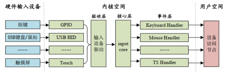
For application development, we only need to care about the data sent from kernel space to user space.
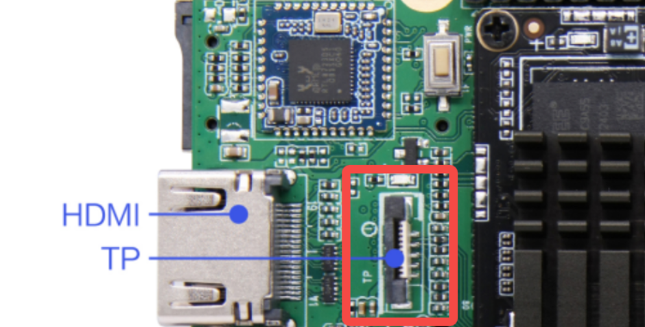
2 I2C Touch Board Card Interface
3 Touch Screen Usage - Command Line Method
3.1 Device Tree Parsing
Tips
The file path below: out/kernel/src_tmp/linux-5.10/arch/arm64/boot/dts/rockchip/ Need to compile the source code first.
Below is a simple analysis of the touch controller node mounted on the I2C1 bus.
Warning
There are two touch controllers mounted on the SoC's I2C1 bus. The following uses the Goodix GT911 touch IC node equipped with the test screen as an example.
First, the basic definition layer (rk3568.dtsi):
i2c1: i2c@fe5a0000 {
    compatible = "rockchip,rk3399-i2c";
    reg = <0x0 0xfe5a0000 0x0 0x1000>;
    clocks = <&cru CLK_I2C1>, <&cru PCLK_I2C1>;
    clock-names = "i2c", "pclk";
    interrupts = <GIC_SPI 47 IRQ_TYPE_LEVEL_HIGH>;
    pinctrl-names = "default";
    pinctrl-0 = <&i2c1_xfer>;
    #address-cells = <1>;
    #size-cells = <0>;
    status = "disabled";
};
Rockchip's basic definition device tree source files do not provide direct I2C touch controller node descriptions, but provide general I2C controller node descriptions on the I2C bus. The reason is simple: to prevent device trees from becoming too lengthy and complex, which is exactly the original intention of using device trees. Below is a simple analysis of the i2c1 node.
compatible: Specifies compatibility, supports RK3399 I2C controllerreg: Register address range (0xfe5a0000-0xfe5a0fff)interrupts: Interrupt number 47, high-level triggeredclocks: I2C function clock (CLK_I2C1) and APB clock (PCLK_I2C1)pinctrl-0: Uses i2c1_xfer pin group by defaultstatus: Default disabled state
Next is the pin configuration layer (rk3568-pinctrl.dtsi)
i2c1_xfer: i2c1-xfer {
    rockchip,pins =
        /* i2c1_scl */
        <0 RK_PB3 1 &pcfg_pull_none_smt>,
        /* i2c1_sda */
        <0 RK_PB4 1 &pcfg_pull_none_smt>;
};
..............

touch_gpio: touch-gpio {
    rockchip,pins =
        /* Interrupt pin */
        <0 RK_PB5 RK_FUNC_GPIO &pcfg_pull_up>,
        /* Reset pin */
        <0 RK_PB6 RK_FUNC_GPIO &pcfg_pull_none>;
};
The above two nodes are the pin configuration nodes for the I2C1 bus and touch chip respectively. They correspond to I2C1's SCL and SDA pins, as well as the touch chip's interrupt pin and reset pin.
i2c1_xfer: I2C1 bus pins, using GPIO0_B3 as SCL, GPIO0_B4 as SDAtouch_gpio: Touch chip control pins, GPIO0_B5 as interrupt pin (pull-up), GPIO0_B6 as reset pin
Finally, let's look at the board-level configuration layer (rk3568-toybrick.dtsi):
&i2c1 {
    status = "okay";

    gt9xx: gt9xx@5d {
        compatible = "goodix,gt9xx";
        status = "okay";
        reg = <0x5d>;
        reset-gpio = <&gpio0 RK_PB6 GPIO_ACTIVE_HIGH>;
        touch-gpio = <&gpio0 RK_PB5 IRQ_TYPE_LEVEL_LOW>;
        max-x = <7200>;
        max-y = <1280>;
        tp-size = <911>;
        pinctrl-names = "default";
        pinctrl-0 = <&touch_gpio>;
        power-supply = <&vcc3v3_lcd0_n>;
    };
};
This node is used to set related parameters of the touch screen, such as maximum coordinates, number of touch points, etc. The specific content is as follows:
&i2c1: References the i2c1 node from the basic definitionstatus = "okay": Enables the I2C1 controller and gt9xx touch chipreg = <0x5d>: I2C slave device address of gt911 chip is 0x5dreset-gpio: Reset pin uses GPIO0_B6, high level activetouch-gpio: Interrupt pin uses GPIO0_B5, low level triggeredmax-x/max-y: Touch screen resolution 7200x1280tp-size = <911>: Specifies touch chip model as gt911power-supply: Power supply comes from vcc3v3_lcd0_n
3.2 Application Layer Testing Method for Touch Related Devices
The touch screen belongs to the input subsystem device. The input subsystem is a unified driver framework provided by Linux for input devices. The driver methods for input devices such as keys, keyboards, touch screens, and mice are similar. Input devices driven by the input subsystem can submit to the kernel through a unified data structure. This data structure includes the input time, type, code, and specific key values or coordinates. The kernel passes it to user space through file interfaces under the /dev/input directory.
getevent debugging tool:
The input subsystem device can use the getevent command to obtain events reported to the system:
geteventis a debugging tool under Android/Linux system- Used to monitor and display raw input events generated by the kernel input subsystem
- Can see the bottom-level, unprocessed hardware input signals
The board has built-in the getevent command, which can be used to debug whether the touch screen is working properly.
In the /dev/input directory, use the command:
geteventYou can obtain all input sub-devices and monitor all device reported events.
Event format parsing:
The returned event format: device: type code value
Event type table:
| Type Code | Event Type | Description |
|---|---|---|
| 0000 | EV_SYN | Synchronization event |
| 0001 | EV_KEY | Key event |
| 0003 | EV_ABS | Absolute coordinate event (touch screen) |
Event code table:
| Code | Name | Description |
|---|---|---|
| 0035 | ABS_MT_POSITION_X | X coordinate |
| 0036 | ABS_MT_POSITION_Y | Y coordinate |
| 0039 | ABS_MT_TRACKING_ID | Touch point ID |
| 0000 | SYN_REPORT | Report synchronization |
| 0002 | SYN_MT_REPORT | Multi-touch report |
Event value description:
| Value Type | Meaning |
|---|---|
| Coordinate value | Hexadecimal coordinate |
| 00000000 | New touch point start |
| ffffffff | Touch point end |
| 00000001 | Key press |
| 00000000 | Key release |
Monitoring specific devices:
If you want to monitor specific sub-devices and their reported event types, you can use the command:
getevent -l /dev/input/event*It will give real-time feedback on hexadecimal coordinate information (x, y), touch point ID and synchronization events. Below is an explanation of event types and event codes.
Linux input event types:
| Event Type | Function | Typical Application |
|---|---|---|
| EV_KEY | Key event | Power key, volume key |
| EV_ABS | Absolute coordinate event | Touch screen, game joystick |
| EV_REL | Relative coordinate event | Mouse movement, scroll wheel |
| EV_SYN | Synchronization event | End of data frame flag |
| EV_MSC | Miscellaneous event | Other type events |
| EV_SW | Switch event | Lid open/close, headphone plug/unplug |
Common touch screen event codes:
| Code Name | Function | Description |
|---|---|---|
| ABS_MT_TRACKING_ID | Touch point ID | Positive=new touch, ffffffff=touch end |
| ABS_MT_POSITION_X | X coordinate | Touch point horizontal coordinate |
| ABS_MT_POSITION_Y | Y coordinate | Touch point vertical coordinate |
| ABS_MT_PRESSURE | Pressure value | Touch pressure size |
| ABS_MT_TOUCH_MAJOR | Touch area | Contact area size |
3.3 Specific Function Demonstration
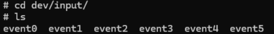
3.3.1 Viewing Input Devices
First, enter the directory /dev/input/, you can see several input events:
3.3.2 Identifying Touch Screen Device
Use the command getevent to view the input device corresponding to input events:
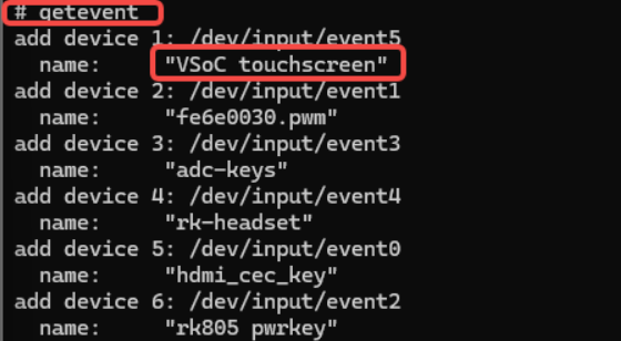
Obviously, the device named "touchscreen" is our touch screen.
3.3.3 Monitoring Touch Events
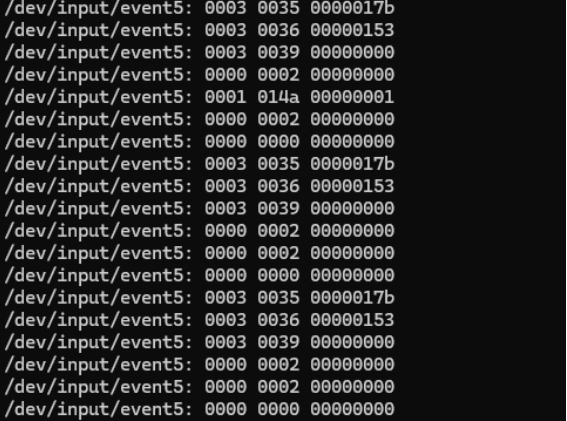
In the screen-on state, click the screen, and you can view the corresponding touch events in the terminal:
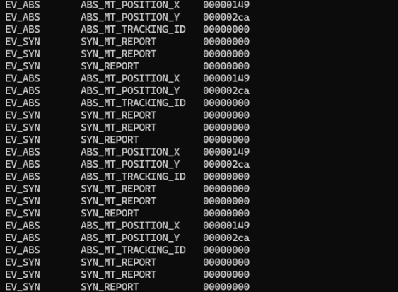
3.3.4 More Readable Event Display
We use a more readable command getevent -l /dev/input/event* to test again. After clicking the screen, the screen returns information as follows: