HOME
Shop
  • English
  • 简体中文
HOME
Shop
  • English
  • 简体中文
  • Product Series

    • FPGA+ARM

      • GM-3568JHF

        • 1. Introduction

          • About GM-3568JHF
        • 2. Quick Start

          • 00 Introduction
          • 01 Environment Setup
          • 02 Compilation Instructions
          • 03 Flashing Guide
          • 04 Debug Tools
          • 05 Software Update
          • 06 View Information
          • 07 Test Commands
          • 08 App Compilation
          • 09 Source Code Acquisition
        • 3. Peripherals and Interfaces

          • 01 USB
          • 02 Display and Touch
          • 03 Ethernet
          • 04 WIFI
          • 05 Bluetooth
          • 06 TF-Card
          • 07 Audio
          • 08 Serial Port
          • 09 CAN
          • 10 RTC
        • 4. Application Development

          • 01 UART read and write case
          • 02 Key detection case
          • 03 LED light flashing case
          • 04 MIPI screen detection case
          • 05 Read USB device information example
          • 06 FAN Detection Case
          • 07 FPGA FSPI Communication Case
          • 08 FPGA DMA read and write case
          • 09 GPS debugging case
          • 10 Ethernet Test Cases
          • 11 RS485 reading and writing examples
          • 12 FPGA IIC read and write examples
          • 13 PN532 NFC card reader case
          • 14 TF card reading and writing case
        • 5. QT Development

          • 01 ARM64 cross compiler environment construction
          • 02 QT program added automatic startup service
        • 6. RKNN_NPU Development

          • 01 RK3568 NPU Overview
          • 02 Development Environment Setup
          • Run Official YOLOv5 Example
          • Model Conversion Detailed Explanation
          • Run Custom Model on Board
        • 7. FPGA Development

          • ARM and FPGA Communication
          • /fpga-arm/GM-3568JHF/FPGA/ch02-FPGA-Development-Manual.html
        • 8. Others

          • 01 Modification of the root directory file system
          • 02 System auto-start service
        • 9. Download

          • Download Resources
    • ShimetaPi

      • M4-R1

        • 1. Introduction

          • 1.1 About M4-R1
        • 2. Quick Start

          • 2.1 OpenHarmony Overview
          • 2.2 Image Burning
          • 2.3 Development Environment Preparation
          • 2.4 Hello World Application
        • 3. Application Development

          • 3.1 Getting Started

            • 3.1.1 ArkTS Language Overview
            • 3.1.2 UI Components (Part 1)
            • 3.1.3 UI Components (Part 2)
            • 3.1.4 UI Components (Part 3)
          • 3.2 Advanced

            • 3.2.1 Getting Started Guide
            • 3.2.2 Usage of Third Party Libraries
            • 3.2.3 Deployment of the Application
            • 3.2.4 Factory Reset
            • 3.2.5 System Debug
            • 3.2.6 APP Stability Testing
            • 3.2.7 Application Testing
          • 3.3 Getting Docs

            • 3.3.1 Official Website Information
          • 3.4 Development Instructions

            • 3.4.1 Full SDK
            • 3.4.2 Introduction of Third Party Libraries
            • 3.4.3 Introduction of HDC Tool
            • 3.4.4 Restore Factory Mode
            • 3.4.5 Update System API
          • 3.5 First Application

            • 3.5.1 First ArkTS App
          • 3.6 Application Demo

            • 3.6.1 UART Tool
            • 3.6.2 Graphics Tablet
            • 3.6.3 Digital Clock
            • 3.6.4 WIFI Tool
        • 4. Device Development

          • 4.1 Ubuntu Environment Development

            • 4.1.1 Environment Setup
            • 4.1.2 Download Source Code
            • 4.1.3 Compile Source Code
          • 4.2 Using DevEco Device Tool

            • 4.2.1 Tool Introduction
            • 4.2.2 Environment Construction
            • 4.2.3 Import SDK
            • 4.2.4 Function Introduction
        • 5. Peripherals and Interfaces

          • 5.1 Raspberry Pi Interfaces
          • 5.2 GPIO Interface
          • 5.3 I2C Interface
          • 5.4 SPI Communication
          • 5.5 PWM Control
          • 5.6 Serial Port Communication
          • 5.7 TF Card Slot
          • 5.8 Display Screen
          • 5.9 Touch Screen
          • 5.10 Audio
          • 5.11 RTC
          • 5.12 Ethernet
          • 5.13 M.2
          • 5.14 MINI PCIE
          • 5.15 Camera
          • 5.16 WIFI BT
          • 5.17 HAT
        • 6. FAQ

          • 6.1 Download Link
      • M5-R1

        • 1. Introduction

          • M5-R1 Development Documentation
        • 2. Quick Start

          • OpenHarmony Overview
          • Image Burning
          • Development Environment Preparation
          • Hello World Application and Deployment
        • 3. Peripherals and Interfaces

          • 3.1 Raspberry Pi Interfaces
          • 3.2 GPIO Interface
          • 3.3 I2C Interface
          • 3.4 SPI Communication
          • 3.5 PWM Control
          • 3.6 Serial Port Communication
          • 3.7 TF Card Slot
          • 3.8 Display Screen
          • 3.9 Touch Screen
          • 3.10 Audio
          • 3.11 RTC
          • 3.12 Ethernet
          • 3.13 M.2
          • 3.14 MINI PCIE
          • 3.15 Camera
          • 3.16 WIFI BT
          • 3.17 HAT
        • 4. Application Development

          • 4.1 Getting Started

            • 4.1.1 ArkTS Language Overview
            • 4.1.2 UI Components (Part 1)
            • 4.1.3 UI Components (Part 2)
            • 4.1.4 UI Components (Part 3)
          • 4.2 Advanced

            • 4.2.1 Getting Started Guide
            • 4.2.2 Usage of Third Party Libraries
            • 4.2.3 Deployment of the Application
            • 4.2.4 Factory Reset
            • 4.2.5 System Debug
            • 4.2.6 APP Stability Testing
            • 4.2.7 Application Testing
        • 5. Device Development

          • 5.1 Environment Setup
          • 5.2 Download Source Code
          • 5.3 Compile Source Code
        • 6. Download

          • Data Download
    • OpenHarmony

      • SC-3568HA

        • 1. Introduction

          • 1.1 About SC-3568HA
        • 2. Quick Start

          • 2.1 OpenHarmony Overview
          • 2.2 Image Burning
          • 2.3 Development Environment Preparation
          • 2.4 Hello World Application
        • 3. Application Development

          • 3.1 ArkUI

            • 3.1.1 ArkTS Language Overview
            • 3.1.2 UI Components (Part 1)
            • 3.1.3 UI Components (Part 2)
            • 3.1.4 UI Components (Part 3)
          • 3.2 Advanced

            • 3.2.1 Getting Started Guide
            • 3.2.2 Usage of Third Party Libraries
            • 3.2.3 Deployment of the Application
            • 3.2.4 Factory Reset
            • 3.2.5 System Debug
            • 3.2.6 APP Stability Testing
            • 3.2.7 Application Testing
        • 4. Device Development

          • 4.1 Environment Setup
          • 4.2 Download Source Code
          • 4.3 Compile Source Code
        • 5. Peripherals and Interfaces

          • 5.1 Raspberry Pi Interfaces
          • 5.2 GPIO Interface
          • 5.3 I2C Interface
          • 5.4 SPI Communication
          • 5.5 PWM Control
          • 5.6 Serial Port Communication
          • 5.7 TF Card Slot
          • 5.8 Display Screen
          • 5.9 Touch Screen
          • 5.10 Audio
          • 5.11 RTC
          • 5.12 Ethernet
          • 5.13 M.2
          • 5.14 MINI PCIE
          • 5.15 Camera
          • 5.16 WIFI BT
          • 5.17 HAT
        • 6. FAQ

          • 6.1 Download Link
      • M-K1HSE

        • 1. Introduction

          • 1.1 Product Introduction
        • 2. Quick Start

          • 2.1 Debug Tool Installation
          • 2.2 Development Environment Setup
          • 2.3 Source Code Download
          • 2.4 Build Instructions
          • 2.5 Flashing Guide
          • 2.6 APT Update Sources
          • 2.7 View Board Info
          • 2.8 CLI LED and Key Test
          • 2.9 GCC Build Programs
        • 3. Application Development

          • 3.1 Basic Application Development

            • 3.1.1 Development Environment Preparation
            • 3.1.2 First Application HelloWorld
            • 3.1.3 Develop HAR Package
          • 3.2 Peripheral Application Cases

            • 3.2.1 UART Read/Write
            • 3.2.2 Key Demo
            • 3.2.3 LED Flash
        • 4. Peripherals and Interfaces

          • 4.1 Standard Peripherals

            • 4.1.1 USB
            • 4.1.2 Display and Touch
            • 4.1.3 Ethernet
            • 4.1.4 WIFI
            • 4.1.5 Bluetooth
            • 4.1.6 TF Card
            • 4.1.7 Audio
            • 4.1.8 Serial Port
            • 4.1.9 CAN
            • 4.1.10 RTC
          • 4.2 Interfaces

            • 4.2.1 Audio
            • 4.2.2 RS485
            • 4.2.3 Display
            • 4.2.4 Touch
        • 5. System Customization Development

          • 5.1 System Porting
          • 5.2 System Customization
          • 5.3 Driver Development
          • 5.4 System Debugging
          • 5.5 OTA Upgrade
        • 6. Download

          • 6.1 Download
    • EVS-Camera

      • CF-NRS1

        • 1. Introduction

          • 1.1 About CF-NRS1
          • 1.2 Event-Based Concepts
          • 1.3 Quick Start
          • 1.4 Resources
        • 2. Development

          • 2.1 Development Overview

            • 2.1.1 Shimetapi Hybrid Camera SDK Introduction
          • 2.2 Environment & API

            • 2.2.1 Environment Overview
            • 2.2.2 Development API Overview
          • 2.3 Linux Development

            • 2.3.1 Linux SDK Introduction
            • 2.3.2 Linux SDK API
            • 2.3.3 Linux Algorithm
            • 2.3.4 Linux Algorithm API
          • 2.4 Service & Web

            • 2.4.1 EVS Server
            • 2.4.2 Time Server
            • 2.4.3 EVS Web
        • 3. Download

          • 3.1 Download
        • 4. Common Problems

          • 4.1 Common Problems
      • CF-CRA2

        • 1. Introduction

          • 1.1 About CF-CRA2
        • 2. Download

          • 2.1 Download
      • EVS Module

        • 1. Related Concepts
        • 2. Hardware Preparation and Environment Configuration
        • 3. Example Program User Guide
        • Resources Download
    • AI-model

      • 1684XB-32T

        • 1. Introduction

          • AIBOX-1684XB-32 Introduction
        • 2. Quick Start

          • First time use
          • Network Configuration
          • Disk usage
          • Memory allocation
          • Fan Strategy
          • Firmware Upgrade
          • Cross-Compilation
          • Model Quantization
        • 3. Application Development

          • 3.1 Development Introduction

            • Sophgo SDK Development
            • SOPHON-DEMO Introduction
          • 3.2 Large Language Models

            • Deploying Llama3 Example
            • /ai-model/AIBOX-1684XB-32/application-development/LLM/Sophon_LLM_api_server-Development-AIBOX-1684XB-32.html
            • /ai-model/AIBOX-1684XB-32/application-development/LLM/MiniCPM-V-2_6-AIBOX-1684XB-32.html
            • /ai-model/AIBOX-1684XB-32/application-development/LLM/Qwen-2-5-VL-demo-Development-AIBOX-1684XB-32.html
            • /ai-model/AIBOX-1684XB-32/application-development/LLM/Qwen-3-chat-demo-Development-AIBOX-1684XB-32.html
            • /ai-model/AIBOX-1684XB-32/application-development/LLM/Qwen3-Qwen Agent-MCP.html
            • /ai-model/AIBOX-1684XB-32/application-development/LLM/Qwen3-langchain-AI Agent.html
          • 3.3 Deep Learning

            • ResNet (Image Classification)
            • LPRNet (License Plate Recognition)
            • SAM (Universal Image Segmentation Foundation Model)
            • YOLOv5 (Object Detection)
            • OpenPose (Human Keypoint Detection)
            • PP-OCR (Optical Character Recognition)
        • 4. Download

          • Resource Download
      • 1684X-416T

        • 1. Introduction

          • AIBOX-1684X-416 Introduction
        • 2. Demo Simple Operation Guide

          • Simple instructions for using shimeta smart monitoring demo
      • RDK-X5

        • 1. Introduction

          • RDK-X5 Hardware Introduction
        • 2. Quick Start

          • RDK-X5 Quick Start
        • 3. Application Development

          • 3.1 AI Online Model Development

            • AI Online Development - Experiment01
            • AI Online Development - Experiment02
            • AI Online Development - Experiment03
            • AI Online Development - Experiment04
            • AI Online Development - Experiment05
            • AI Online Development - Experiment06
          • 3.2 Large Language Models (Voice)

            • Voice LLM Application - Experiment01
            • Voice LLM Application - Experiment02
            • Voice LLM Application - Experiment03
            • Voice LLM Application - Experiment04
            • Voice LLM Application - Experiment05
            • Voice LLM Application - Experiment06
          • 3.3 40pin-IO Development

            • 40pin IO Development - Experiment01
            • 40pin IO Development - Experiment02
            • 40pin IO Development - Experiment03
            • 40pin IO Development - Experiment04
            • 40pin IO Development - Experiment05
            • 40pin IO Development - Experiment06
            • 40pin IO Development - Experiment07
          • 3.4 USB Module Development

            • USB Module Usage - Experiment01
            • USB Module Usage - Experiment02
          • 3.5 Machine Vision

            • Machine Vision Technology Development - Experiment01
            • Machine Vision Technology Development - Experiment02
            • Machine Vision Technology Development - Experiment03
            • Machine Vision Technology Development - Experiment04
          • 3.6 ROS2 Base Development

            • ROS2 Basic Development - Experiment01
            • ROS2 Basic Development - Experiment02
            • ROS2 Basic Development - Experiment03
            • ROS2 Basic Development - Experiment04
      • RDK-S100

        • 1. Introduction

          • 1.1 About RDK-S100
        • 2. Quick Start

          • 2.1 First Use
        • 3. Application Development

          • 3.1 AI Online Model Development

            • 3.1.1 Volcano Engine Doubao AI
            • 3.1.2 Image Analysis
            • 3.1.3 Multimodal Visual Analysis
            • 3.1.4 Multimodal Image Comparison
            • 3.1.5 Multimodal Document Analysis
            • 3.1.6 Camera AI Vision Analysis
          • 3.2 Large Language Models

            • 3.2.1 Speech Recognition
            • 3.2.2 Voice Conversation
            • 3.2.3 Multimodal Image Analysis
            • 3.2.4 Multimodal Image Comparison
            • 3.2.5 Multimodal Document Analysis
            • 3.2.6 Multimodal Vision Application
          • 3.3 40pin-IO Development

            • 3.3.1 GPIO Output LED Blink
            • 3.3.2 GPIO Input
            • 3.3.3 Key Control LED
            • 3.3.4 PWM Output
            • 3.3.5 Serial Output
            • 3.3.6 I2C Experiment
          • 3.4 USB Module Development

            • 3.4.1 USB Voice Module
            • 3.4.2 Sound Source Localization
          • 3.5 Machine Vision

            • 3.5.1 USB Camera
            • 3.5.2 Image Processing Basics
            • 3.5.3 Object Detection
            • 3.5.4 Image Segmentation
          • 3.6 ROS2 Base Development

            • 3.6.1 Environment Setup
            • 3.6.2 Create and Build Workspace
            • 3.6.3 ROS2 Topic Communication
            • 3.6.4 ROS2 Camera Application
    • Core-Board

      • C-3568BQ

        • 1. Introduction

          • C-3568BQ Introduction
      • C-3588LQ

        • 1. Introduction

          • C-3588LQ Introduction
      • GC-3568JBAF

        • 1. Introduction

          • GC-3568JBAF Introduction
      • C-K1BA

        • 1. Introduction

          • C-K1BA Introduction

14 Ethernet

1 Ethernet Introduction

1.1 Introduction to RK3568 Network Card

When mentioning networking, many friends must have heard the term "network card". In the past, if computers needed to go online, they had to buy a network card and insert it, just like today's discrete graphics desktops. The reason is that with the continuous development of technology, now only one chip is needed to implement the wired network card function. Therefore, network card chips are directly placed on the motherboard (generally speaking, following the network cable interface).

Embedded network hardware is divided into two parts: MAC and PHY. Some SoCs claim to support networking, which means they have integrated network MAC peripherals. Common general SoCs generally integrate network MAC peripherals, such as RK series, I.MX series, STM32MP1 series, etc. The advantage of integration is that it can significantly improve network speed (such as using network-specific DMA), support 10/100/1000M network speed, and only need to connect an external PHY chip. (If MAC peripheral is not integrated, most use integrated MAC+PHY network chips). MAC connects to external PHY chips through MII/RMII interface or GMII/RGMII interface to complete network data transmission.

RK3568 kernel integrates two 10M/100M/1000M network MACs, complying with IEEE802.3-2002 standard. The MAC layer supports full-duplex or half-duplex operation programmable, with a. The MAC is dedicated DMA with direct memory interface, formats data into packets complying with IEEE802.3-2002 standard, and transmits these data to the Ethernet physical interface (PHY). It can also move packets from RXFIFO to microprocessor memory. The main features of RK3568's internal ENET peripheral are as follows:

  • ①, Supports full-duplex and half-duplex operation.
  • ②, Full-duplex flow control operation (IEEE 802.3X pause packets and priority flow control)
  • ③, Header and frame start data (SFD) are automatically inserted in transmit mode, automatically deleted in receive.
  • ④, CRC and pad auto-generation can be controlled frame by frame
  • ⑤, Programmable packet length, supports standard Ethernet packets or giant Ethernet packets up to 16KB
  • ⑥, Programmable packet gap
  • ⑦, Two groups of FIFO: one 4096-byte transmit FIFO with programmable threshold function and one 4096-byte receive FIFO with configurable threshold function

1.2 Basic Introduction to IP Address, Subnet Mask, Default Gateway, DNS Server

For computers to achieve network communication, they must have a network address for quick positioning. IP is 32-bit binary data, usually expressed in decimal and separated by ".". IP address is the unique identity ID of a computer in the network. Just like express delivery needs a specific residential address in the real world, IP address = network address + host address (also known as: host number and network number)

So how to distinguish between network address and host address in an IP address? This requires the subnet mask. When the value of the subnet mask is 255, the corresponding bit of the IP address is the network address bit. For example, IP address: 192.168.22.88, subnet mask is 255.255.255.0, then 192.168.22 is the network address. The network address is used to determine which LAN you are in, such as finding your home or company's network. The host address is used to determine your position within the LAN. For example, 192.168.22.88 is the network IP of your living room TV, and 192.168.22.66 is the network IP of your home computer. When the network is disconnected, devices in the LAN can communicate with each other. For example, after a phone connects to the router's network, you can enter the IP to access its backend for management.

The gateway can be understood as a tool to send data from the LAN to the outside. The specific parsing process is not introduced here.

Since IP addresses are hard to remember, we usually input a website address when browsing the internet, such as "baidu.com". The function of DNS is to map this website name to the IP address, so you can enter the website to access the corresponding IP server.

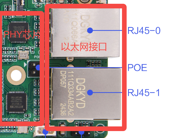
2 Ethernet Board Card Interface

Ethernet Interface

3 Ethernet Usage - Command Line Method

3.1 Device Tree Parsing

Tips

The file path below: out/kernel/src_tmp/linux-5.10/arch/arm64/boot/dts/rockchip Need to compile the source code first.

In this project, the configuration of Ethernet nodes follows the three-layer structure of the device tree as follows:

Basic definition layer, taking gmac0 as an example (rk3568.dtsi):

gmac0: ethernet@fe2a0000 {
    compatible = "rockchip,rk3568-gmac", "snps,dwmac-4.20a";
    reg = <0x0 0xfe2a0000 0x0 0x10000>;
    interrupts = <GIC_SPI 27 IRQ_TYPE_LEVEL_HIGH>,
                 <GIC_SPI 24 IRQ_TYPE_LEVEL_HIGH>;
    interrupt-names = "macirq", "eth_wake_irq";
    rockchip,grf = <&grf>;
    clocks = <&cru SCLK_GMAC0>, <&cru SCLK_GMAC0_RX_TX>,
             <&cru SCLK_GMAC0_RX_TX>, <&cru CLK_MAC0_REFOUT>,
             <&cru ACLK_GMAC0>, <&cru PCLK_GMAC0>,
             <&cru SCLK_GMAC0_RX_TX>, <&cru CLK_GMAC0_PTP_REF>,
             <&cru PCLK_XPCS>;
    clock-names = "stmmaceth", "mac_clk_rx",
                  "mac_clk_tx", "clk_mac_refout",
                  "aclk_mac", "pclk_mac",
                  "clk_mac_speed", "ptp_ref",
                  "pclk_xpcs";
    resets = <&cru SRST_A_GMAC0>;
    reset-names = "stmmaceth";
    snps,mixed-burst;
    snps,tso;
    status = "disabled";

    mdio0: mdio {
        compatible = "snps,dwmac-mdio";
        #address-cells = <0x1>;
        #size-cells = <0x0>;
    };
};
  • compatible: Specifies compatibility, supports RK3568 GMAC and standard DWC Ethernet MAC 4.20a
  • reg: Register address range (0xfe2a0000-0xfe2affff)
  • interrupts: MAC interrupt number 27 and wake interrupt number 24, both high-level triggered
  • clocks: Contains 9 clock sources, covering MAC core clock, RX/TX clock, reference clock, etc.
  • snps,mixed-burst: Enable mixed burst transfer mode
  • snps,tso: Enable TCP segmentation offload function
  • mdio0: Built-in MDIO bus controller for PHY management
  • status: Default disabled state

Pin configuration layer (rk3568-pinctrl.dtsi):

//GMAC0 RGMII mode pin configuration:

gmac0_miim: gmac0-miim {
    rockchip,pins =
        /* gmac0_mdc */
        <2 RK_PC3 2 &pcfg_pull_none>,
        /* gmac0_mdio */
        <2 RK_PC4 2 &pcfg_pull_none>;
};

gmac0_rgmii_clk: gmac0-rgmii-clk {
    rockchip,pins =
        /* gmac0_rxclk */
        <2 RK_PA5 2 &pcfg_pull_none>,
        /* gmac0_txclk */
        <2 RK_PB0 2 &pcfg_pull_none_drv_level_1>;
};

gmac0_rgmii_bus: gmac0-rgmii-bus {
    rockchip,pins =
        /* gmac0_rxd2 */
        <2 RK_PA3 2 &pcfg_pull_none>,
        /* gmac0_rxd3 */
        <2 RK_PA4 2 &pcfg_pull_none>,
        /* gmac0_txd2 */
        <2 RK_PA6 2 &pcfg_pull_none_drv_level_2>,
        /* gmac0_txd3 */
        <2 RK_PA7 2 &pcfg_pull_none_drv_level_2>;
};

gmac0_tx_bus2: gmac0-tx-bus2 {
    rockchip,pins =
        /* gmac0_txd0 */
        <2 RK_PB3 1 &pcfg_pull_none_drv_level_2>,
        /* gmac0_txd1 */
        <2 RK_PB4 1 &pcfg_pull_none_drv_level_2>,
        /* gmac0_txen */
        <2 RK_PB5 1 &pcfg_pull_none>;
};
...........

//GMAC1 provides two pin configuration modes:

/* M0 mode - uses GPIO3 group */
gmac1m0_rgmii_clk: gmac1m0-rgmii-clk {
    rockchip,pins =
        /* gmac1_rxclkm0 */
        <3 RK_PA7 3 &pcfg_pull_none>,
        /* gmac1_txclkm0 */
        <3 RK_PA6 3 &pcfg_pull_none_drv_level_1>;
};

/* M1 mode - uses GPIO4 group */
gmac1m1_miim: gmac1m1-miim {
    rockchip,pins =
        /* gmac1_mdcm1 */
        <4 RK_PB6 3 &pcfg_pull_none>,
        /* gmac1_mdiom1 */
        <4 RK_PB7 3 &pcfg_pull_none>;
};
  • gmac0: Uses GPIO2 group pins, supports RGMII Gigabit Ethernet
  • gmac1m0: Uses GPIO3 group pins, suitable for single network port design
  • gmac1m1: Uses GPIO4 group pins, suitable for dual network port design

Finally, let's look at the board-level configuration layer (rk3568-toybrick-x0.dtsi):

&gmac0 {
    phy-mode = "rgmii";
    clock_in_out = "output";

    snps,reset-gpio = <&gpio2 RK_PD3 GPIO_ACTIVE_LOW>;
    snps,reset-active-low;
    snps,reset-delays-us = <0 20000 100000>;

    assigned-clocks = <&cru SCLK_GMAC0_RX_TX>, <&cru SCLK_GMAC0>;
    assigned-clock-parents = <&cru SCLK_GMAC0_RGMII_SPEED>, <&cru CLK_MAC0_2TOP>;
    assigned-clock-rates = <0>, <125000000>;

    pinctrl-names = "default";
    pinctrl-0 = <&gmac0_miim
                 &gmac0_tx_bus2
                 &gmac0_rx_bus2
                 &gmac0_rgmii_clk
                 &gmac0_rgmii_bus>;

    tx_delay = <0x2d>;
    rx_delay = <0x13>;

    phy-handle = <&rgmii_phy0>;
    status = "okay";
};

&mdio0 {
    rgmii_phy0: phy@0 {
        compatible = "ethernet-phy-ieee802.3-c22";
        reg = <0x0>;
    };
};
  • &gmac0: References the gmac0 node from the basic definition
  • phy-mode = "rgmii": Configured as RGMII Gigabit Ethernet mode
  • clock_in_out = "output": Clock output mode
  • snps,reset-gpio: PHY reset pin uses GPIO2_D3, low level active
  • snps,reset-delays-us: Reset timing: 0ms pre-delay, 20ms reset duration, 100ms post-reset delay
  • assigned-clock-rates: Sets GMAC clock frequency to 125MHz
  • tx_delay/rx_delay: RGMII interface transmit/receive delay compensation
  • phy-handle: Associates with rgmii_phy0 PHY device
  • rgmii_phy0: IEEE 802.3 standard compatible PHY chip, MDIO address is 0

3.2 Application Layer Testing Network Methods

On the development board, you can use the following common commands to test the network (note: x.x.x.x is the network card address):

ifconfig        # View network interfaces in the device
ping x.x.x.x   # Test if the network is normal by exchanging packets with a specific network
ifconfig eth0 X.X.X.X up      # Enable network
ifconfig eth0 X.X.X.X down    # Disable network

3.3 Specific Demonstration of Network Testing Function

We take Ethernet interface 1 as an example and connect the network cable for testing:

Connect Network Cable

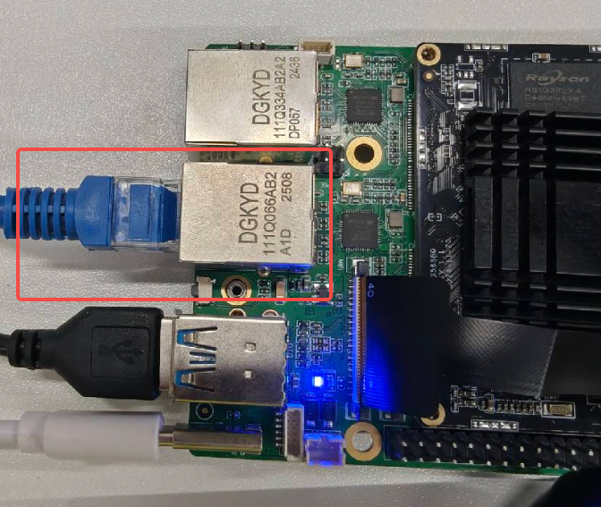
After plugging in, enter the command ifconfig in the terminal to view the network port information:

View Network Port Information

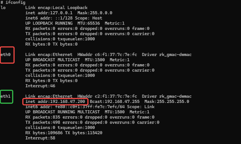
The system successfully recognizes two Ethernet interfaces. You can see that the interface with the network cable inserted is assigned a network IP, and the broadcast address, subnet mask, and other information are displayed.

Now enter the command ping baidu.com to test the network connection:

Network Connection Test

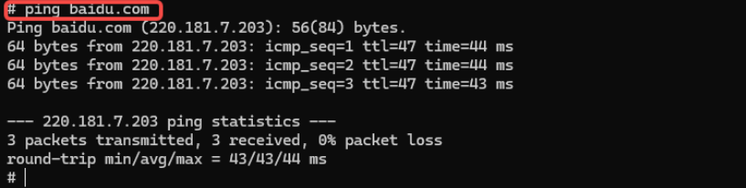
Three groups of data were sent, no packet loss. At this point, the system can successfully connect to Ethernet.

4. Ethernet Usage - Official Library Method

Data Path

hap package: /05-Development-Materials/01-OpenHarmony-Development-Materials/Peripheral-Test-APP/HAP/NET_TEST.hap

Source code: /05-Development-Materials/01-OpenHarmony-Development-Materials/Peripheral-Test-APP/SRC/NATEWORK_TEST

We have also written a network test example here, but it uses the official network library @kit.NetworkKit. Essentially it is also NAPI, but OpenHarmony officials have already encapsulated it for us, so we just need to call it.

Since OpenHarmony's official ArkTS network library is sufficient for our network development needs. This time we use the built-in network library for writing, which can greatly improve our development speed and also expand a development method for everyone!

4-1 Test APP Implementation Effect

Let's look at the effect of the test APP implementation:

The first column will display the network connection status, connection type, and local IP address

Network Status Display

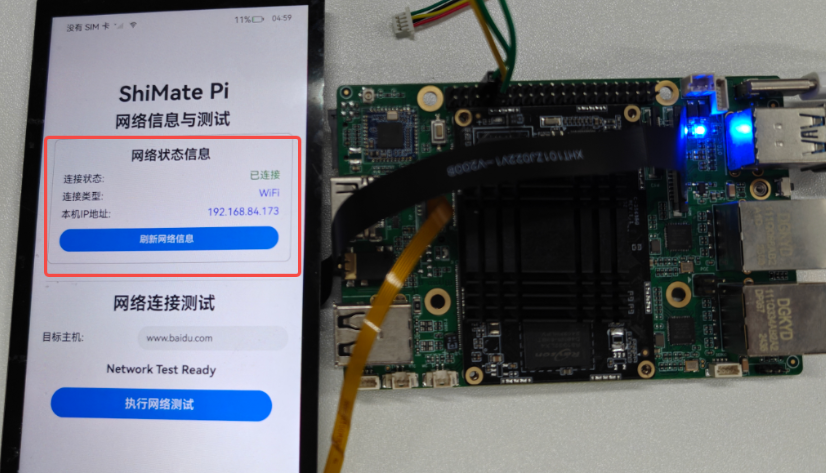
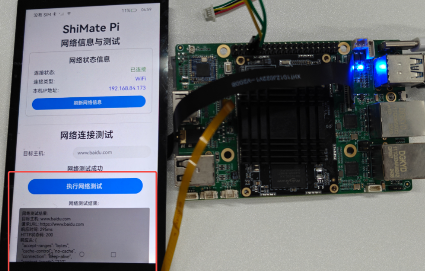
Click network test, it will send an HTTP request to test the network

Network Test Result

Below is an introduction to several related functions involved:

4.2 Network Related API Function Introduction

1. connection.getDefaultNet()

  • Function: Get the default network connection handle of the current device
  • Return value: NetHandle object (representing active network connection)

2. connection.getNetCapabilities(netHandle)

  • Function: Get network capability information
  • Return value: bearerTypes: Network bearer type array

3. connection.getConnectionProperties(netHandle)

  • Function: Get network connection properties

4. http.createHttp()

  • Function: Create HTTP request object

5. httpRequest.request(url, options)

  • Function: Send HTTP request

6. httpRequest.destroy()

  • Function: Destroy HTTP request object

4.3 Network Test APP Code Implementation

Here is the ets code for friends who need to study:

import { hilog } from '@kit.PerformanceAnalysisKit';
import { connection } from '@kit.NetworkKit';
import { socket } from '@kit.NetworkKit';
import { http } from '@kit.NetworkKit';

const DOMAIN = 0x0000;

@Entry
@Component
struct Index {
  @State currentIpAddress: string = 'Getting...';
  @State networkMessage: string = 'Network Test Ready';
  @State networkResult: string = '';
  @State isNetworkLoading: boolean = false;
  @State targetHost: string = 'www.baidu.com';
  @State connectionType: string = 'Unknown';
  @State isConnected: boolean = false;

  build() {
    Row() {
      Column() {
        Text('ShiMate Pi')
          .fontSize(40)
          .fontWeight(FontWeight.Bold)
          .margin({ bottom: 10 })
        Text('Network Information & Test')
          .fontSize(30)
          .fontWeight(FontWeight.Bold)
          .margin({ bottom: 10 })

        // Network status information card
        Column() {
          Text('Network Status Information')
            .fontSize(24)
            .fontWeight(FontWeight.Bold)
            .margin({ bottom: 15 })

          Row() {
            Text('Connection Status: ')
              .fontSize(18)
              .fontWeight(FontWeight.Medium)
            Text(this.isConnected ? 'Connected' : 'Disconnected')
              .fontSize(18)
              .fontColor(this.isConnected ? Color.Green : Color.Red)
          }
          .width('100%')
          .justifyContent(FlexAlign.SpaceBetween)
          .margin({ bottom: 10 })

          Row() {
            Text('Connection Type: ')
              .fontSize(18)
              .fontWeight(FontWeight.Medium)
            Text(this.connectionType)
              .fontSize(18)
              .fontColor(Color.Blue)
          }
          .width('100%')
          .justifyContent(FlexAlign.SpaceBetween)
          .margin({ bottom: 10 })

          Row() {
            Text('Local IP Address: ')
              .fontSize(18)
              .fontWeight(FontWeight.Medium)
            Text(this.currentIpAddress)
              .fontSize(18)
              .fontColor(Color.Blue)
          }
          .width('100%')
          .justifyContent(FlexAlign.SpaceBetween)
          .margin({ bottom: 15 })

          Button('Refresh Network Info')
            .fontSize(16)
            .width('100%')
            .height(40)
            .onClick(() => {
              this.getNetworkInfo();
            })
        }
        .width('90%')
        .padding(20)
        .backgroundColor(Color.White)
        .borderRadius(10)
        .border({ width: 1, color: Color.Gray })
        .margin({ bottom: 30 })

        // Network test section
        Divider()
          .width('90%')
          .margin({ bottom: 20 })

        Text('Network Connection Test')
          .fontSize(30)
          .fontWeight(FontWeight.Bold)
          .margin({ bottom: 20 })

        // Target host input box
        Row() {
          Text('Target Host: ')
            .fontSize(18)
            .fontWeight(FontWeight.Medium)

          TextInput({ placeholder: 'Please enter host address', text: this.targetHost })
            .fontSize(16)
            .width('60%')
            .onChange((value: string) => {
              this.targetHost = value;
            })
        }
        .width('90%')
        .justifyContent(FlexAlign.SpaceBetween)
        .margin({ bottom: 20 })

        Text(this.networkMessage)
          .fontSize(20)
          .fontWeight(FontWeight.Bold)
          .margin({ bottom: 20 })

        Button('Execute Network Test')
          .fontSize(20)
          .width('80%')
          .height(50)
          .enabled(!this.isNetworkLoading)
          .onClick(() => {
            this.runNetworkTest();
          })
          .margin({ bottom: 20 })

        if (this.isNetworkLoading) {
          Text('Executing Network Test...')
            .fontSize(16)
            .fontColor(Color.Blue)
            .margin({ bottom: 10 })
        }

        if (this.networkResult) {
          Column() {
            Text('Network Test Result:')
              .fontSize(16)
              .fontWeight(FontWeight.Bold)
              .margin({ bottom: 5 })

            Scroll() {
              Text(this.networkResult)
                .fontSize(14)
                .fontColor(Color.Black)
                .backgroundColor(Color.Gray)
                .padding(10)
                .borderRadius(5)
                .width('100%')
                .textAlign(TextAlign.Start)
            }
            .width('100%')
            .height(200)
            .scrollable(ScrollDirection.Vertical)
            .scrollBar(BarState.Auto)
          }
          .width('90%')
        }
      }
      .width('100%')
      .justifyContent(FlexAlign.Start)
      .alignItems(HorizontalAlign.Center)
      .padding({ top: 10 })
    }
    .height('100%')
  }

  aboutToAppear() {
    // Get network info when page loads
    this.getNetworkInfo();
  }

  private async getNetworkInfo() {
    try {
      // Get network connection status
      const netHandle = await connection.getDefaultNet();
      if (netHandle) {
        this.isConnected = true;

        // Get network capability information
        const netCapabilities = await connection.getNetCapabilities(netHandle);
        if (netCapabilities) {
          // Determine connection type
          if (netCapabilities.bearerTypes.includes(connection.NetBearType.BEARER_WIFI)) {
            this.connectionType = 'WiFi';
          } else if (netCapabilities.bearerTypes.includes(connection.NetBearType.BEARER_CELLULAR)) {
            this.connectionType = 'Mobile Network';
          } else if (netCapabilities.bearerTypes.includes(connection.NetBearType.BEARER_ETHERNET)) {
            this.connectionType = 'Ethernet';
          } else {
            this.connectionType = 'Other';
          }
        }

        // Get IP address - using JSON serialization method
        const linkProperties = await connection.getConnectionProperties(netHandle);
        if (linkProperties) {
          // Extract first IPv4 address from serialized info
          const serialized: string = JSON.stringify(linkProperties);
          const match: RegExpMatchArray | null = serialized.match(/\b(?:\d{1,3}\.){3}\d{1,3}\b/);
          const ip: string = match ? match[0] : '';
          this.currentIpAddress = ip && ip !== '127.0.0.1' ? ip : 'None';
        } else {
          this.currentIpAddress = 'None';
        }
      } else {
        this.isConnected = false;
        this.connectionType = 'Not Connected';
        this.currentIpAddress = 'None';
      }
    } catch (error) {
      hilog.error(DOMAIN, 'NetworkInfo', 'Failed to get network info: %{public}s', String(error));
      this.isConnected = false;
      this.connectionType = 'Get Failed';
      this.currentIpAddress = 'Get Failed';
    }
  }

  private async runNetworkTest() {
    this.isNetworkLoading = true;
    this.networkMessage = 'Network Test in Progress...';
    this.networkResult = '';

    if (!this.targetHost || this.targetHost.trim() === '') {
      this.networkResult = 'Error: Please enter a valid target host address';
      this.networkMessage = 'Network Test Failed';
      this.isNetworkLoading = false;
      return;
    }

    try {
      const startTime = Date.now();

      // Use HTTP request to test network connection
      const httpRequest = http.createHttp();

      const url = this.targetHost.startsWith('http') ? this.targetHost : `https://${this.targetHost}`;

      const response = await httpRequest.request(url, {
        method: http.RequestMethod.GET,
        connectTimeout: 10000,
        readTimeout: 10000,
        header: {
          'User-Agent': 'OpenHarmony-NetworkTest/1.0'
        }
      });

      const endTime = Date.now();
      const responseTime = endTime - startTime;

      let resultText = `Network Test Result:\n`;
      resultText += `Target Host: ${this.targetHost}\n`;
      resultText += `Request URL: ${url}\n`;
      resultText += `Response Time: ${responseTime}ms\n`;
      resultText += `HTTP Status Code: ${response.responseCode}\n`;
      resultText += `Response Header: ${JSON.stringify(response.header, null, 2)}\n`;

      if (response.responseCode >= 200 && response.responseCode < 400) {
        resultText += `Connection Status: Success\n`;
        this.networkMessage = 'Network Test Success';
      } else {
        resultText += `Connection Status: Failed (HTTP ${response.responseCode})\n`;
        this.networkMessage = 'Network Test Failed';
      }

      // If response body is not too large, show part of the content
      if (response.result && typeof response.result === 'string' && response.result.length < 500) {
        resultText += `Response Content Preview: ${response.result.substring(0, 200)}...\n`;
      }

      this.networkResult = resultText;

      httpRequest.destroy();

      hilog.info(DOMAIN, 'Network_Test', 'Network test completed for %{public}s: %{public}d ms', this.targetHost, responseTime);
    } catch (error) {
      const errorMessage = String(error);
      this.networkResult = `Network Test Failed:\nTarget Host: ${this.targetHost}\nError Message: ${errorMessage}\n\nPossible Reasons:\n1. Network connection unavailable\n2. Target host cannot be accessed\n3. DNS resolution failed\n4. Firewall blocking connection`;
      this.networkMessage = 'Network Test Error';
      hilog.error(DOMAIN, 'Network_Test', 'Network test error for %{public}s: %{public}s', this.targetHost, errorMessage);
    } finally {
      this.isNetworkLoading = false;
    }
  }
}
Edit this page on GitHub
Last Updated:
Contributors: ZSL