06 GPIO Introduction
GPIO (General-Purpose Input/Output) is general-purpose input/output port, is the most basic and commonly used interface on a chip for digital signal (0 and 1) communication with external devices or circuits. Each GPIO pin can be configured as input or output mode through software, thereby achieving:
- Input mode: reads external signals (e.g., button state, sensor high/low level)
- Output mode: controls external devices (e.g., turning on LEDs, controlling relays, sending simple signals)
Among them, RK3568 provides up to five GPIO banks (groups), usually labeled GPIO0 to GPIO4. Each bank has 32 pins (but not all pins are exposed). Theoretically up to 160 GPIO, but the actual usable number depends on the chip's specific package and pin multiplexing.
General IO output levels are 1.8V, 3.0V, 3.3V, etc. Different output voltages depend on the IO's power-domain voltage, which relates to hardware power supply. For this example using RK3568, different IOs correspond to the following voltage domains:
- GPIO0: typically in 3.3V voltage domain
- GPIO1 ~ GPIO4: typically in 1.8V voltage domain (some models may support 3.3V; please refer to the specific manual)
It should also be noted that GPIO naming uses the Rockchip pin ID, which is formed by controller(bank) + port + index(pin).
- The number of controllers is equal to the number of GPIO controllers
- Ports are fixed as A, B, C, and D; each port has only 8 indices (a=0, b=1, c=2, d=3)
- Index numbers are fixed 0, 1, 2, 3, 4, 5, 6, 7
RK3568 has 5 GPIO controllers; each controller can control 32 IOs. When used as GPIO, port behavior is configured by GPIO controller registers.
Example: GPIO1_A4 means the first group controller, port A, index 4. The pin number calculation is 32 x 1 + 0 x 8 + 4 = 36. GPIO5_B3 yields 32 x 5 + 8 x 1 + 3 = 171
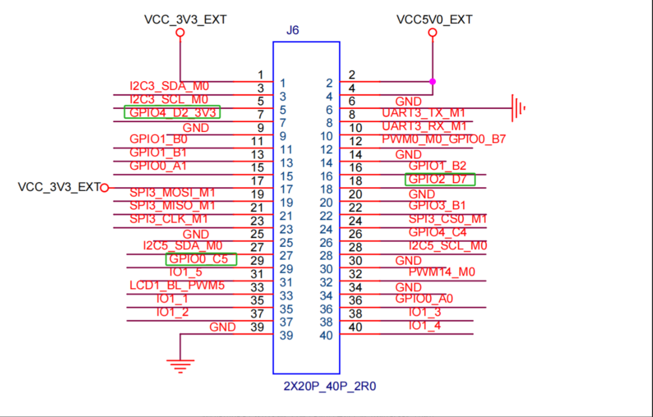
1 GPIO Board Interface
2 GPIO Usage --- Command Line Method
2.1 Principle Introduction
Using the common echo command as an example, the Linux kernel provides a set of user-space interfaces for debugging GPIO under the /sys/class/gpio/ directory.
This directory is the control interface exposed by the Linux kernel GPIO subsystem to user space via Sysfs. Sysfs is a virtual filesystem that presents kernel devices, drivers, modules, etc. as files and directories, mounted under the /sys directory; /sys/class/ is one such category.
2.2 Common Commands to Operate GPIO
We use the HDC tool to enter the corresponding directory of the board in the terminal to operate GPIO:
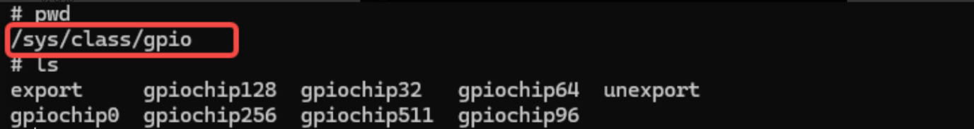
Among them:
- export file is used to notify the system to export the GPIO pins to be controlled
- unexport is used to notify the system to unexport (because user-space cannot directly operate the kernel to control GPIO; after using this command, Linux kernel will create a user-access interface, i.e., create a control file; unexport will release resources and delete the control file)
- gpiochipN stores information about GPIO registers in the system, including each register's starting pin number base, register name, and total pins
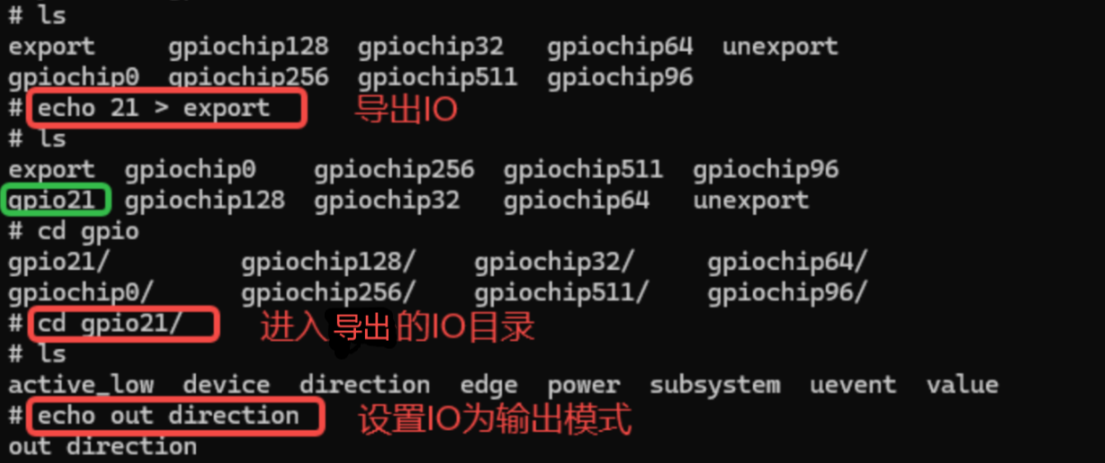
An example exporting GPIO0_C5. First compute the pin number: GPIO0_C5 = 8 x 2 + 5 = 21.
Export GPIO pin:
Info
In the following commands, the part before '#' is the file path, and the part after '#' is the instruction. In actual use, you only need to input the corresponding command!!!
It is recommended that everyone follow the tutorial and type the commands manually as you go through it.
console:/sys/class/gpio# echo 21 > exportSet direction: "in" for input, "out" for output:
console:/sys/class/gpio/gpio21# echo out > directionCheck direction: use the cat command
console:/sys/class/gpio/gpio21# cat directionSet output high level:
console:/sys/class/gpio/gpio21# echo 1 > valueCheck input/output (switch to input mode first):
console:/sys/class/gpio/gpio21# cat valueUnexport:
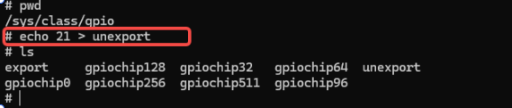
console:/sys/class/gpio# echo 21 > unexportThe above operations require ensuring the IO is multiplexed to the GPIO function to perform normal GPIO operations.
2.3 Demonstration of Specific Functions
On the board, use the above commands to operate, go to the /sys/class/gpio/ directory, and perform the following actions:
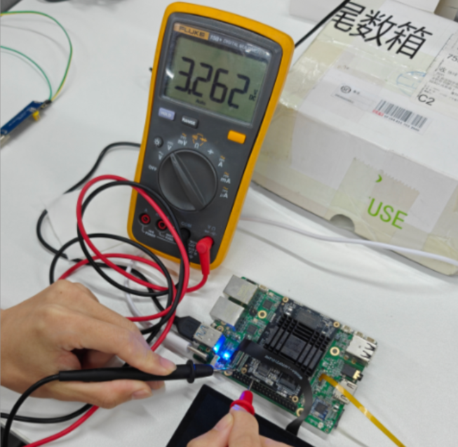
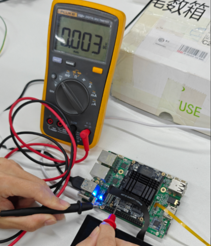
Set IO0_C5 to a high level output:

Use a multimeter to measure the pin; successfully output high level:
Then set IO0_C5 to a low level output:
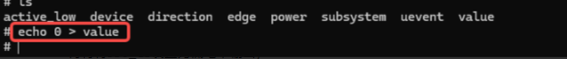
Use a multimeter to measure the pin; successfully output low level:
Return to the parent directory and unexport the IO:
3 GPIO Usage --- NAPI Method
Documentation path
hap package: /05-Development-Materials/01-OpenHarmony-Development-Materials/Peripheral-Test-APP/HAP/GPIO_TEST.hap
Project source code: /05-Development-Materials/01-OpenHarmony-Development-Materials/Peripheral-Test-APP/SRC/GPIO_TEST