HOME
Shop
  • English
  • 简体中文
HOME
Shop
  • English
  • 简体中文
  • Product Series

    • FPGA+ARM

      • GM-3568JHF

        • 1. Introduction

          • About GM-3568JHF
        • 2. Quick Start

          • 00 Introduction
          • 01 Environment Setup
          • 02 Compilation Instructions
          • 03 Flashing Guide
          • 04 Debug Tools
          • 05 Software Update
          • 06 View Information
          • 07 Test Commands
          • 08 App Compilation
          • 09 Source Code Acquisition
        • 3. Peripherals and Interfaces

          • 01 USB
          • 02 Display and Touch
          • 03 Ethernet
          • 04 WIFI
          • 05 Bluetooth
          • 06 TF-Card
          • 07 Audio
          • 08 Serial Port
          • 09 CAN
          • 10 RTC
        • 4. Application Development

          • 01 UART read and write case
          • 02 Key detection case
          • 03 LED light flashing case
          • 04 MIPI screen detection case
          • 05 Read USB device information example
          • 06 FAN Detection Case
          • 07 FPGA FSPI Communication Case
          • 08 FPGA DMA read and write case
          • 09 GPS debugging case
          • 10 Ethernet Test Cases
          • 11 RS485 reading and writing examples
          • 12 FPGA IIC read and write examples
          • 13 PN532 NFC card reader case
          • 14 TF card reading and writing case
        • 5. QT Development

          • 01 ARM64 cross compiler environment construction
          • 02 QT program added automatic startup service
        • 6. RKNN_NPU Development

          • 01 RK3568 NPU Overview
          • 02 Development Environment Setup
          • Run Official YOLOv5 Example
          • Model Conversion Detailed Explanation
          • Run Custom Model on Board
        • 7. FPGA Development

          • ARM and FPGA Communication
          • /fpga-arm/GM-3568JHF/FPGA/ch02-FPGA-Development-Manual.html
        • 8. Others

          • 01 Modification of the root directory file system
          • 02 System auto-start service
        • 9. Download

          • Download Resources
    • ShimetaPi

      • M4-R1

        • 1. Introduction

          • 1.1 About M4-R1
        • 2. Quick Start

          • 2.1 OpenHarmony Overview
          • 2.2 Image Burning
          • 2.3 Development Environment Preparation
          • 2.4 Hello World Application
        • 3. Application Development

          • 3.1 Getting Started

            • 3.1.1 ArkTS Language Overview
            • 3.1.2 UI Components (Part 1)
            • 3.1.3 UI Components (Part 2)
            • 3.1.4 UI Components (Part 3)
          • 3.2 Advanced

            • 3.2.1 Getting Started Guide
            • 3.2.2 Usage of Third Party Libraries
            • 3.2.3 Deployment of the Application
            • 3.2.4 Factory Reset
            • 3.2.5 System Debug
            • 3.2.6 APP Stability Testing
            • 3.2.7 Application Testing
          • 3.3 Getting Docs

            • 3.3.1 Official Website Information
          • 3.4 Development Instructions

            • 3.4.1 Full SDK
            • 3.4.2 Introduction of Third Party Libraries
            • 3.4.3 Introduction of HDC Tool
            • 3.4.4 Restore Factory Mode
            • 3.4.5 Update System API
          • 3.5 First Application

            • 3.5.1 First ArkTS App
          • 3.6 Application Demo

            • 3.6.1 UART Tool
            • 3.6.2 Graphics Tablet
            • 3.6.3 Digital Clock
            • 3.6.4 WIFI Tool
        • 4. Device Development

          • 4.1 Ubuntu Environment Development

            • 4.1.1 Environment Setup
            • 4.1.2 Download Source Code
            • 4.1.3 Compile Source Code
          • 4.2 Using DevEco Device Tool

            • 4.2.1 Tool Introduction
            • 4.2.2 Environment Construction
            • 4.2.3 Import SDK
            • 4.2.4 Function Introduction
        • 5. Peripherals and Interfaces

          • 5.1 Raspberry Pi Interfaces
          • 5.2 GPIO Interface
          • 5.3 I2C Interface
          • 5.4 SPI Communication
          • 5.5 PWM Control
          • 5.6 Serial Port Communication
          • 5.7 TF Card Slot
          • 5.8 Display Screen
          • 5.9 Touch Screen
          • 5.10 Audio
          • 5.11 RTC
          • 5.12 Ethernet
          • 5.13 M.2
          • 5.14 MINI PCIE
          • 5.15 Camera
          • 5.16 WIFI BT
          • 5.17 HAT
        • 6. FAQ

          • 6.1 Download Link
      • M5-R1

        • 1. Introduction

          • M5-R1 Development Documentation
        • 2. Quick Start

          • OpenHarmony Overview
          • Image Burning
          • Development Environment Preparation
          • Hello World Application and Deployment
        • 3. Peripherals and Interfaces

          • 3.1 Raspberry Pi Interfaces
          • 3.2 GPIO Interface
          • 3.3 I2C Interface
          • 3.4 SPI Communication
          • 3.5 PWM Control
          • 3.6 Serial Port Communication
          • 3.7 TF Card Slot
          • 3.8 Display Screen
          • 3.9 Touch Screen
          • 3.10 Audio
          • 3.11 RTC
          • 3.12 Ethernet
          • 3.13 M.2
          • 3.14 MINI PCIE
          • 3.15 Camera
          • 3.16 WIFI BT
          • 3.17 HAT
        • 4. Application Development

          • 4.1 Getting Started

            • 4.1.1 ArkTS Language Overview
            • 4.1.2 UI Components (Part 1)
            • 4.1.3 UI Components (Part 2)
            • 4.1.4 UI Components (Part 3)
          • 4.2 Advanced

            • 4.2.1 Getting Started Guide
            • 4.2.2 Usage of Third Party Libraries
            • 4.2.3 Deployment of the Application
            • 4.2.4 Factory Reset
            • 4.2.5 System Debug
            • 4.2.6 APP Stability Testing
            • 4.2.7 Application Testing
        • 5. Device Development

          • 5.1 Environment Setup
          • 5.2 Download Source Code
          • 5.3 Compile Source Code
        • 6. Download

          • Data Download
    • OpenHarmony

      • SC-3568HA

        • 1. Introduction

          • 1.1 About SC-3568HA
        • 2. Quick Start

          • 2.1 OpenHarmony Overview
          • 2.2 Image Burning
          • 2.3 Development Environment Preparation
          • 2.4 Hello World Application
        • 3. Application Development

          • 3.1 ArkUI

            • 3.1.1 ArkTS Language Overview
            • 3.1.2 UI Components (Part 1)
            • 3.1.3 UI Components (Part 2)
            • 3.1.4 UI Components (Part 3)
          • 3.2 Advanced

            • 3.2.1 Getting Started Guide
            • 3.2.2 Usage of Third Party Libraries
            • 3.2.3 Deployment of the Application
            • 3.2.4 Factory Reset
            • 3.2.5 System Debug
            • 3.2.6 APP Stability Testing
            • 3.2.7 Application Testing
        • 4. Device Development

          • 4.1 Environment Setup
          • 4.2 Download Source Code
          • 4.3 Compile Source Code
        • 5. Peripherals and Interfaces

          • 5.1 Raspberry Pi Interfaces
          • 5.2 GPIO Interface
          • 5.3 I2C Interface
          • 5.4 SPI Communication
          • 5.5 PWM Control
          • 5.6 Serial Port Communication
          • 5.7 TF Card Slot
          • 5.8 Display Screen
          • 5.9 Touch Screen
          • 5.10 Audio
          • 5.11 RTC
          • 5.12 Ethernet
          • 5.13 M.2
          • 5.14 MINI PCIE
          • 5.15 Camera
          • 5.16 WIFI BT
          • 5.17 HAT
        • 6. FAQ

          • 6.1 Download Link
      • M-K1HSE

        • 1. Introduction

          • 1.1 Product Introduction
        • 2. Quick Start

          • 2.1 Debug Tool Installation
          • 2.2 Development Environment Setup
          • 2.3 Source Code Download
          • 2.4 Build Instructions
          • 2.5 Flashing Guide
          • 2.6 APT Update Sources
          • 2.7 View Board Info
          • 2.8 CLI LED and Key Test
          • 2.9 GCC Build Programs
        • 3. Application Development

          • 3.1 Basic Application Development

            • 3.1.1 Development Environment Preparation
            • 3.1.2 First Application HelloWorld
            • 3.1.3 Develop HAR Package
          • 3.2 Peripheral Application Cases

            • 3.2.1 UART Read/Write
            • 3.2.2 Key Demo
            • 3.2.3 LED Flash
        • 4. Peripherals and Interfaces

          • 4.1 Standard Peripherals

            • 4.1.1 USB
            • 4.1.2 Display and Touch
            • 4.1.3 Ethernet
            • 4.1.4 WIFI
            • 4.1.5 Bluetooth
            • 4.1.6 TF Card
            • 4.1.7 Audio
            • 4.1.8 Serial Port
            • 4.1.9 CAN
            • 4.1.10 RTC
          • 4.2 Interfaces

            • 4.2.1 Audio
            • 4.2.2 RS485
            • 4.2.3 Display
            • 4.2.4 Touch
        • 5. System Customization Development

          • 5.1 System Porting
          • 5.2 System Customization
          • 5.3 Driver Development
          • 5.4 System Debugging
          • 5.5 OTA Upgrade
        • 6. Download

          • 6.1 Download
    • EVS-Camera

      • CF-NRS1

        • 1. Introduction

          • 1.1 About CF-NRS1
          • 1.2 Event-Based Concepts
          • 1.3 Quick Start
          • 1.4 Resources
        • 2. Development

          • 2.1 Development Overview

            • 2.1.1 Shimetapi Hybrid Camera SDK Introduction
          • 2.2 Environment & API

            • 2.2.1 Environment Overview
            • 2.2.2 Development API Overview
          • 2.3 Linux Development

            • 2.3.1 Linux SDK Introduction
            • 2.3.2 Linux SDK API
            • 2.3.3 Linux Algorithm
            • 2.3.4 Linux Algorithm API
          • 2.4 Service & Web

            • 2.4.1 EVS Server
            • 2.4.2 Time Server
            • 2.4.3 EVS Web
        • 3. Download

          • 3.1 Download
        • 4. Common Problems

          • 4.1 Common Problems
      • CF-CRA2

        • 1. Introduction

          • 1.1 About CF-CRA2
        • 2. Download

          • 2.1 Download
      • EVS Module

        • 1. Related Concepts
        • 2. Hardware Preparation and Environment Configuration
        • 3. Example Program User Guide
        • Resources Download
    • AI-model

      • 1684XB-32T

        • 1. Introduction

          • AIBOX-1684XB-32 Introduction
        • 2. Quick Start

          • First time use
          • Network Configuration
          • Disk usage
          • Memory allocation
          • Fan Strategy
          • Firmware Upgrade
          • Cross-Compilation
          • Model Quantization
        • 3. Application Development

          • 3.1 Development Introduction

            • Sophgo SDK Development
            • SOPHON-DEMO Introduction
          • 3.2 Large Language Models

            • Deploying Llama3 Example
            • /ai-model/AIBOX-1684XB-32/application-development/LLM/Sophon_LLM_api_server-Development-AIBOX-1684XB-32.html
            • /ai-model/AIBOX-1684XB-32/application-development/LLM/MiniCPM-V-2_6-AIBOX-1684XB-32.html
            • /ai-model/AIBOX-1684XB-32/application-development/LLM/Qwen-2-5-VL-demo-Development-AIBOX-1684XB-32.html
            • /ai-model/AIBOX-1684XB-32/application-development/LLM/Qwen-3-chat-demo-Development-AIBOX-1684XB-32.html
            • /ai-model/AIBOX-1684XB-32/application-development/LLM/Qwen3-Qwen Agent-MCP.html
            • /ai-model/AIBOX-1684XB-32/application-development/LLM/Qwen3-langchain-AI Agent.html
          • 3.3 Deep Learning

            • ResNet (Image Classification)
            • LPRNet (License Plate Recognition)
            • SAM (Universal Image Segmentation Foundation Model)
            • YOLOv5 (Object Detection)
            • OpenPose (Human Keypoint Detection)
            • PP-OCR (Optical Character Recognition)
        • 4. Download

          • Resource Download
      • 1684X-416T

        • 1. Introduction

          • AIBOX-1684X-416 Introduction
        • 2. Demo Simple Operation Guide

          • Simple instructions for using shimeta smart monitoring demo
      • RDK-X5

        • 1. Introduction

          • RDK-X5 Hardware Introduction
        • 2. Quick Start

          • RDK-X5 Quick Start
        • 3. Application Development

          • 3.1 AI Online Model Development

            • AI Online Development - Experiment01
            • AI Online Development - Experiment02
            • AI Online Development - Experiment03
            • AI Online Development - Experiment04
            • AI Online Development - Experiment05
            • AI Online Development - Experiment06
          • 3.2 Large Language Models (Voice)

            • Voice LLM Application - Experiment01
            • Voice LLM Application - Experiment02
            • Voice LLM Application - Experiment03
            • Voice LLM Application - Experiment04
            • Voice LLM Application - Experiment05
            • Voice LLM Application - Experiment06
          • 3.3 40pin-IO Development

            • 40pin IO Development - Experiment01
            • 40pin IO Development - Experiment02
            • 40pin IO Development - Experiment03
            • 40pin IO Development - Experiment04
            • 40pin IO Development - Experiment05
            • 40pin IO Development - Experiment06
            • 40pin IO Development - Experiment07
          • 3.4 USB Module Development

            • USB Module Usage - Experiment01
            • USB Module Usage - Experiment02
          • 3.5 Machine Vision

            • Machine Vision Technology Development - Experiment01
            • Machine Vision Technology Development - Experiment02
            • Machine Vision Technology Development - Experiment03
            • Machine Vision Technology Development - Experiment04
          • 3.6 ROS2 Base Development

            • ROS2 Basic Development - Experiment01
            • ROS2 Basic Development - Experiment02
            • ROS2 Basic Development - Experiment03
            • ROS2 Basic Development - Experiment04
      • RDK-S100

        • 1. Introduction

          • 1.1 About RDK-S100
        • 2. Quick Start

          • 2.1 First Use
        • 3. Application Development

          • 3.1 AI Online Model Development

            • 3.1.1 Volcano Engine Doubao AI
            • 3.1.2 Image Analysis
            • 3.1.3 Multimodal Visual Analysis
            • 3.1.4 Multimodal Image Comparison
            • 3.1.5 Multimodal Document Analysis
            • 3.1.6 Camera AI Vision Analysis
          • 3.2 Large Language Models

            • 3.2.1 Speech Recognition
            • 3.2.2 Voice Conversation
            • 3.2.3 Multimodal Image Analysis
            • 3.2.4 Multimodal Image Comparison
            • 3.2.5 Multimodal Document Analysis
            • 3.2.6 Multimodal Vision Application
          • 3.3 40pin-IO Development

            • 3.3.1 GPIO Output LED Blink
            • 3.3.2 GPIO Input
            • 3.3.3 Key Control LED
            • 3.3.4 PWM Output
            • 3.3.5 Serial Output
            • 3.3.6 I2C Experiment
          • 3.4 USB Module Development

            • 3.4.1 USB Voice Module
            • 3.4.2 Sound Source Localization
          • 3.5 Machine Vision

            • 3.5.1 USB Camera
            • 3.5.2 Image Processing Basics
            • 3.5.3 Object Detection
            • 3.5.4 Image Segmentation
          • 3.6 ROS2 Base Development

            • 3.6.1 Environment Setup
            • 3.6.2 Create and Build Workspace
            • 3.6.3 ROS2 Topic Communication
            • 3.6.4 ROS2 Camera Application
    • Core-Board

      • C-3568BQ

        • 1. Introduction

          • C-3568BQ Introduction
      • C-3588LQ

        • 1. Introduction

          • C-3588LQ Introduction
      • GC-3568JBAF

        • 1. Introduction

          • GC-3568JBAF Introduction
      • C-K1BA

        • 1. Introduction

          • C-K1BA Introduction

07 I2C Communication

1 I2C Introduction

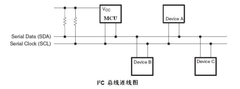
I2C bus controller transmits information between devices connected to the bus via the Serial Data (SDA) line and Serial Clock (SCL) line. Each device has a unique address (whether it is a microcontroller (MCU), LCD driver, memory, or keyboard interface), and can act as a transmitter or receiver (depending on the device's function).

I2C Bus Structure Diagram

1 For a detailed introduction to I2C, please refer to:

For a detailed introduction to I2C, please refer to:

&i2c3{
status = "okay";
};
&i2c5{
status = "okay";
};

In registering I2C devices, an i2c_client structure is required to describe the I2C device. However, in standard Linux, the user only needs to provide the corresponding I2C device information, and Linux will construct the i2c_client structure based on the information provided.

In the SDK we provide, the I2C3 and I2C5 interfaces have already been enabled (these two interfaces are enabled by default) in arch/arm64/boot/dts/rockchip/rk3568-toybrick-x0-linux.dts:

The user-provided I2C device information is written into the DTS file as a node, as shown below:

&i2c3{
    nca9555:nca9555@20{
        reg=<0x20>;
        compatible = "novosense,nca9555";
        status="okay";
        gpio-controller;
        #gpio-cells = <2>;
    };
};

Driver mounts devices by obtaining node information from the DTS. Among these, NCA9555 has already been mounted on I2C3, which is a 24-pin CMOS device providing 16-bit general-purpose parallel I/O expansion via the I2C bus.

3.1 I2C Device Tree Configuration

Below, based on the device tree chapter, we analyze the device tree configuration of I2C3 and I2C5.

Next, according to the device tree chapter, we will analyze the I2C3 and I2C5 device tree configurations.

Tips

The following file path: out/kernel/src_tmp/linux-5.10/arch/arm64/boot/dts/rockchip/ must be built from source code first.

We first locate the basic configuration content for I2C3 and I2C5 in rk3568.dtsi as follows:

i2c3: i2c@fe5c0000 {
compatible = "rockchip,rk3399-i2c";
reg = <0x0 0xfe5c0000 0x0 0x1000>; // register address
clocks = <&cru CLK_I2C3>, <&cru PCLK_I2C3>; // clock configuration
clock-names = "i2c", "pclk";
interrupts = <GIC_SPI 49 IRQ_TYPE_LEVEL_HIGH>; // interrupt configuration
pinctrl-names = "default";
pinctrl-0 = <&i2c3m0_xfer>; // pin multiplexing configuration
#address-cells = <1>;
#size-cells = <0>;
status = "disabled"; // default disabled
};
i2c5: i2c@fe5e0000 {
compatible = "rockchip,rk3399-i2c";
reg = <0x0 0xfe5e0000 0x0 0x1000>; // register address
clocks = <&cru CLK_I2C5>, <&cru PCLK_I2C5>; // clock configuration
clock-names = "i2c", "pclk";
interrupts = <GIC_SPI 51 IRQ_TYPE_LEVEL_HIGH>; // interrupt configuration
pinctrl-names = "default";
pinctrl-0 = <&i2c5m0_xfer>; // pin multiplexing configuration
#address-cells = <1>;
#size-cells = <0>;
status = "disabled"; // default disabled
};

3.2 I2C Pin Configuration

Next, view the I2C pin configuration in rk3568-pinctrl.dtsi:

i2c3m0_xfer: i2c3m0-xfer {
    rockchip,pins =
        /* i2c3_sclm0 - clock line */
        <1 RK_PA1 1 &pcfg_pull_none_smt>,
        /* i2c3_sdam0 - data line */
        <1 RK_PA0 1 &pcfg_pull_none_smt>;
};
i2c5m0_xfer: i2c5m0-xfer {
    rockchip,pins =
        /* i2c5_sclm0 - clock line */
        <3 RK_PB3 4 &pcfg_pull_none_smt>,
        /* i2c5_sdam0 - data line */
        <3 RK_PB4 4 &pcfg_pull_none_smt>;
};

3.3 Board-Level peripheral configurations

Finally, locate the board-level configuration file to view the I2C peripherals' specific configurations

In rk3568-toybrick.dtsi, I2C5 is enabled and configured with sensors:

&i2c5 {
    status = "okay";

    gs_mxc6655xa: gs_mxc6655xa@15 {
        status = "okay";
        compatible = "gs_mxc6655xa";
        pinctrl-names = "default";
        pinctrl-0 = <&mxc6655xa_irq_gpio>;
        reg = <0x15>;
        irq-gpio = <&gpio3 RK_PC1 IRQ_TYPE_LEVEL_LOW>;
        irq_enable = <0>;
        poll_delay_ms = <30>;
        type = <SENSOR_TYPE_ACCEL>;
        power-off-in-suspend = <1>;
        layout = <1>;
    };

    hym8563: hym8563@51 {
        compatible = "haoyu,hym8563";
        reg = <0x51>;
        pinctrl-names = "default";
        pinctrl-0 = <&rtc_int>;
        interrupt-parent = <&gpio0>;
        interrupts = <RK_PD3 IRQ_TYPE_LEVEL_LOW>;
        irq_enable = <0>;
    };
};

Info

MXC6655XA is a digital-output three-axis accelerometer from MEMSIC (MeiXin Semiconductor).

hym8563 is an I2C-based real-time clock (RTC) chip; the development board actually enables this device.

3.2 Operating I2C common instructions

Check I2C devices:

ls /dev/i2c*

Test I2C commands:

The I2C tool is an open-source utility; our SDK has been downloaded and cross-compiled. After compilation, the board generates commands such as i2cdetect, i2cdump, i2cset, i2cget); these can be used directly from the command line:

  • i2cdetect – lists I2C buses and all devices on them
  • i2cdump – displays all registers of an I2C device
  • i2cget – reads a register value from an I2C device
  • i2cset – writes a value to a register on an I2C device

3.3 Demonstrations

Following are common usage examples for the above commands:

1. Detect how many I2C buses are present in the current system:

i2cdetect -l
I2C Bus Detection

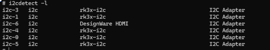
2. View devices on the i2c-3 interface:

i2cdetect -a 3
I2C Device Scan

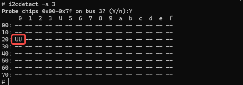
UU indicates that the device at address 0x20 has a driver loaded successfully, i.e., the NCA9555 mounted on I2C3 mentioned above.

3. Read all registers of the selected device:

i2cdump -f -y 3 0x20

(Shows values of all registers from 0x00 to 0xff on the device at address 0x20 on I2C3)

I2C Register Read

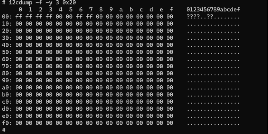
The command executes successfully and outputs data, indicating a device at 0x20 exists on bus 3 and basic communication is working.

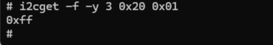
4. Read a specific register of a given I2C device:

i2cget -f -y 3 0x20 0x01

(Read the value of register 0x01 in the device at address 0x20)

I2C Single Register Read

4. I2C Usage — NAPI Method

Info

MXC6655XA is a digital-output three-axis accelerometer hym8563 is an I2C RTC chip; the development board enables only this device

4.1 Kernel Permissions

We run the following command in the terminal to grant permissions for I2C3:

chmod 777 /dev/i2c-3

4.2 Test Program Explanation

To visually observe the data, we use a logic analyzer to capture the transmitted I2C signals and verify the correctness of the data.

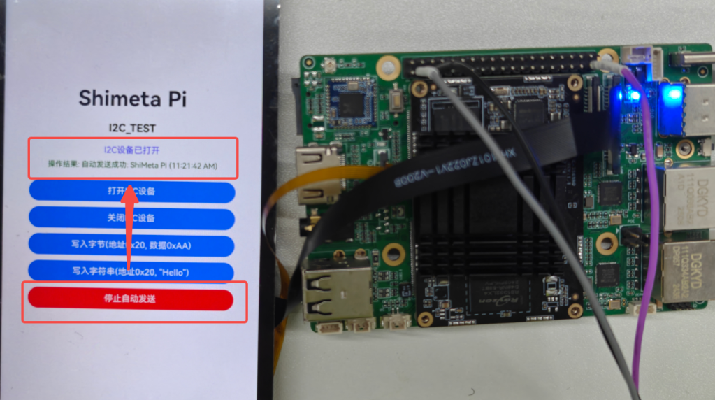
After granting permissions, open the I2C device; after a successful open, click Start to send "Shimeta Pi".

I2C Device Open

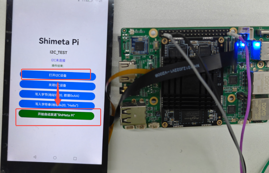
After clicking, I2C3 will send the string "Shimeta Pi" every 100 ms.

I2C Auto Send

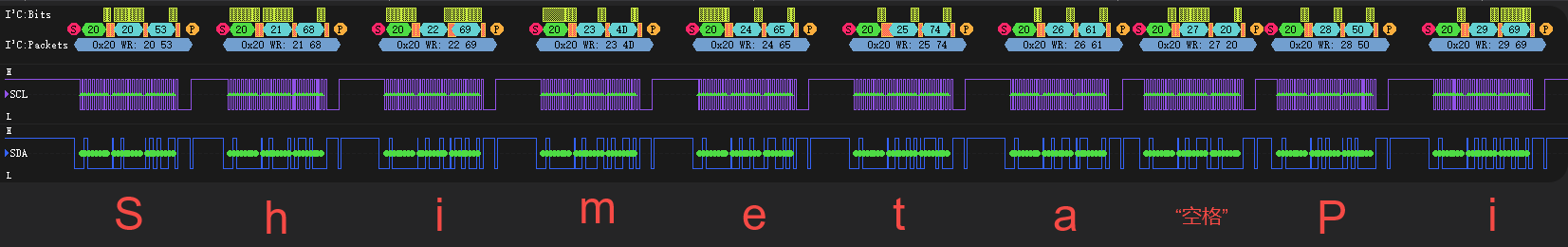
Enabling auto-send, we use a logic analyzer to capture data; the data in 1 second is as follows:

I2C Data Capture

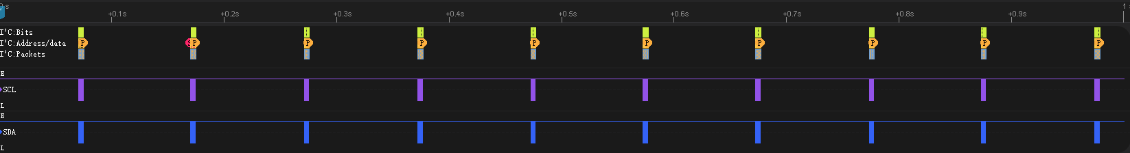
We can see the data being sent every 100 ms as shown above.

We take the last two data as an example for viewing:

I2C Last Two Data

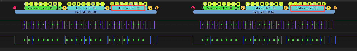
The last two data packets are 0x50 and 0x69, corresponding to decimal 80 and 105. See the ASCII table:

ASCII Table - P Character

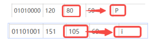
These are exactly the last two data bytes of the string "ShiMeta Pi".

Similarly, the data are arranged as shown in the table below:

CharacterHex ValueDecimal ValueDescription
'S'0x5383Character S
'h'0x68104Character h
'i'0x69105Character i
'M'0x4D77Character M
'e'0x65101Character e
't'0x74116Character t
'a'0x6197Character a
' '0x2032Space
'P'0x5080Character P
'i'0x69105Character i

The values observed on the logic analyzer match the above data exactly.

I2C Data Comparison

4.3 Partial Code Explanation

Here we use reading system nodes to operate the I2C peripheral for read/write operations; only portions of the code are shown for illustration.

First, we introduce the ioctl function, a very important control operation function in the embedded field; think of it as a universal remote that presses the appropriate button on a device to trigger the corresponding operation.

The function prototype is:

int ioctl(int fd, unsigned long request, ...);

Parameter description:

fd is the file descriptor for the device file; request is the request code. For example, after pressing a remote, the remote may transmit an infrared code; the device decodes it. If the decoded value is "0x9E", the device may perform a corresponding action. Similarly, the kernel defines several I2C operations; we simply send the corresponding request code and the kernel will perform the appropriate operation.

... are variadic parameters; different data is sent with different request codes, such as an AC command code "0x88" indicating temperature setting, which means the data could be the temperature data.

Next, the most important function in our program: ioctl(i2c_fd, I2C_RDWR, &i2c_data). It tells the Linux kernel: the I2C controller corresponding to i2c_fd should perform an I2C read/write operation, and the specific data is &i2c_data.

We also look at the kernel's i2c-dev.h file, placed in the same directory as napi_init.cpp, with code as follows:

/*
    i2c-dev.h - i2c-bus driver, char device interface

    Copyright (C) 1995-97 Simon G. Vogl
    Copyright (C) 1998-99 Frodo Looijaard <frodol@dds.nl>

    This program is free software; you can redistribute it and/or modify
    it under the terms of the GNU General Public License as published by
    the Free Software Foundation; either version 2 of the License, or
    (at your option) any later version.

    This program is distributed in the hope that it will be useful,
    but WITHOUT ANY WARRANTY; without even the implied warranty of
    MERCHANTABILITY or FITNESS FOR A PARTICULAR PURPOSE.  See the
    GNU General Public License for more details.

    You should have received a copy of the GNU General Public License
    along with this program; if not, write to the Free Software
    Foundation, Inc., 675 Mass Ave, Cambridge, MA 02139, USA.
*/

#ifndef _LINUX_I2C_DEV_H
#define _LINUX_I2C_DEV_H

#include <linux/types.h>
#include <linux/compiler.h>

/* /dev/i2c-X ioctl commands.  The ioctl's parameter is always an
 * unsigned long, except for:
 *  - I2C_FUNCS, takes pointer to an unsigned long
 *  - I2C_RDWR, takes pointer to struct i2c_rdwr_ioctl_data
 *  - I2C_SMBUS, takes pointer to struct i2c_smbus_ioctl_data
 */

#define I2C_RETRIES 0x0701 /* number of times a device address should
                be polled when not acknowledging */
#define I2C_TIMEOUT 0x0702 /* set timeout in units of 10 ms */

/* NOTE: Slave address is 7 or 10 bits, but 10-bit addresses
 * are NOT supported! (due to code brokenness)
 */
#define I2C_SLAVE   0x0703 /* Use this slave address */
#define I2C_SLAVE_FORCE 0x0706 /* Use this slave address, even if it
                is already in use by a driver! */
#define I2C_TENBIT  0x0704 /* 0 for 7 bit addrs, != 0 for 10 bit */

#define I2C_FUNCS   0x0705 /* Get the adapter functionality mask */

#define I2C_RDWR    0x0707 /* Combined R/W transfer (one STOP only) */

#define I2C_PEC    0x0708 /* != 0 to use PEC with SMBus */
#define I2C_SMBUS   0x0720 /* SMBus transfer */


/* This is the structure as used in the I2C_SMBUS ioctl call */
struct i2c_smbus_ioctl_data {
    __u8 read_write;
    __u8 command;
    __u32 size;
    union i2c_smbus_data __user *data;
};

/* This is the structure as used in the I2C_RDWR ioctl call */
struct i2c_rdwr_ioctl_data {
    struct i2c_msg __user *msgs;   /* pointers to i2c_msgs */
    __u32 nmsgs;         /* number of i2c_msgs */
};

#define  I2C_RDRW_IOCTL_MAX_MSGS    42

#ifdef __KERNEL__
#define I2C_MAJOR   89    /* Device major number    */
#endif

#endif /* _LINUX_I2C_DEV_H */

We can find that mainly there are some macro definitions, defining the operations to be executed when receiving corresponding request codes.

#define I2C_RDWR    0x0707 /* Combined R/W transfer (one STOP only) */
/* This is the structure as used in the I2C_RDWR ioctl call */
struct i2c_rdwr_ioctl_data {
    struct i2c_msg __user *msgs;   /* pointers to i2c_msgs */
    __u32 nmsgs;         /* number of i2c_msgs */
};

We take I2C_RDWR as used in this project as an example (code above). Its function is to perform a complex, combined I2C message transfer. The parameter is a pointer to an i2c_rdwr_ioctl_data. The implementation creates an array of i2c_msg containing read/write operations and combined read/write operations; during the process, only one STOP signal that conforms to the I2C standard is produced.

Now let's look at the NAPI function for sending I2C data:

// I2C write a byte
// Parameter: offset (register offset), data (the byte to write)
// Return: 0 on success, -1 on failure
static napi_value I2cWriteByte(napi_env env, napi_callback_info info)
{
    size_t argc = 2;
    napi_value args[2] = {nullptr};
    napi_value result;

    napi_get_cb_info(env, info, &argc, args, nullptr, nullptr);

    if (argc < 2) {
        napi_create_int32(env, -1, &result);  // Parameter error returns -1
        return result;
    }

    if (!i2c_opened || i2c_fd < 0) {
        napi_create_int32(env, -1, &result);  // Device not opened returns -1
        return result;
    }

    int32_t offset, data;
    napi_get_value_int32(env, args[0], &offset);
    napi_get_value_int32(env, args[1], &data);

    // Use ioctl to directly operate I2C device
    struct i2c_rdwr_ioctl_data i2c_data;
    struct i2c_msg msg;
    unsigned char buf[2];

    buf[0] = (unsigned char)offset;  // Register address
    buf[1] = (unsigned char)data;    // Data to write

    msg.addr = I2C_SLAVE_ADDR;       // I2C device address
    msg.flags = 0;                   // Write operation
    msg.len = 2;                     // Data length
    msg.buf = buf;                   // Data buffer

    i2c_data.msgs = &msg;
    i2c_data.nmsgs = 1;

    int ret = ioctl(i2c_fd, I2C_RDWR, &i2c_data);

    if (ret < 0) {
        OH_LOG_Print(LOG_APP, LOG_ERROR, GLOBAL_RESMGR, I2C_TAG,
                   "I2C write byte failed: %{public}s", strerror(errno));
        napi_create_int32(env, -1, &result);  // Write failed returns -1
        return result;
    }


    OH_LOG_Print(LOG_APP, LOG_INFO, GLOBAL_RESMGR, I2C_TAG,
               "I2C write byte success: addr=0x%{public}02X, offset=0x%{public}02X, data=0x%{public}02X",
               I2C_SLAVE_ADDR, offset, data);

    napi_create_int32(env, 0, &result);  // Success returns 0
    return result;
}

We first look at the function I2cWriteByte; the process is as follows:

  1. Use napi_get_cb_info and napi_get_value_int32 to obtain the offset and data passed from JavaScript
  2. Then write the two data bytes into the i2c_data array
  3. Use ioctl to inform the kernel to perform an I2C_RDWR operation; the data is i2c_data
  4. The lower layers will automatically generate the corresponding I2C start condition, send the two data bytes, and then generate a stop signal to complete the I2C transmission
// I2C write a string
// Parameters: offset (register offset), data (the string to write)
// Return: 0 on success, -1 on failure
static napi_value I2cWriteString(napi_env env, napi_callback_info info)
{
    size_t argc = 2;
    napi_value args[2] = {nullptr};
    napi_value result;

    napi_get_cb_info(env, info, &argc, args, nullptr, nullptr);

    if (argc < 2) {
        napi_create_int32(env, -1, &result);  // Parameter error returns -1
        return result;
    }

    if (!i2c_opened || i2c_fd < 0) {
        napi_create_int32(env, -1, &result);  // Device not opened returns -1
        return result;
    }

    int32_t offset;
    napi_get_value_int32(env, args[0], &offset);

    size_t str_length;
    napi_get_value_string_utf8(env, args[1], nullptr, 0, &str_length);

    if (str_length == 0 || str_length > 256) {
        napi_create_int32(env, -1, &result);  // Invalid string length returns -1
        return result;
    }

    char* str_buffer = new char[str_length + 1];
    napi_get_value_string_utf8(env, args[1], str_buffer, str_length + 1, &str_length);

    // Use ioctl to directly operate I2C device, write byte by byte
    struct i2c_rdwr_ioctl_data i2c_data;
    struct i2c_msg msg;
    unsigned char buf[2];
    int success_count = 0;

    for (size_t i = 0; i < str_length; i++) {
        buf[0] = (unsigned char)(offset + i);  // Register address
        buf[1] = (unsigned char)str_buffer[i]; // Data to write

        msg.addr = I2C_SLAVE_ADDR;             // I2C device address
        msg.flags = 0;                         // Write operation
        msg.len = 2;                           // Data length
        msg.buf = buf;                         // Data buffer

        i2c_data.msgs = &msg;
        i2c_data.nmsgs = 1;

        int ret = ioctl(i2c_fd, I2C_RDWR, &i2c_data);

        if (ret < 0) {
            OH_LOG_Print(LOG_APP, LOG_ERROR, GLOBAL_RESMGR, I2C_TAG,
                       "I2C write string failed at byte %{public}zu: %{public}s", i, strerror(errno));
            break;
        }
        success_count++;
    }

    delete[] str_buffer;

    if (success_count == (int)str_length) {
        OH_LOG_Print(LOG_APP, LOG_INFO, GLOBAL_RESMGR, I2C_TAG,
                   "I2C write string success: addr=0x%{public}02X, offset=0x%{public}02X, length=%{public}d",
                   I2C_SLAVE_ADDR, offset, success_count);

        napi_create_int32(env, 0, &result);  // Success returns 0
    } else {
        OH_LOG_Print(LOG_APP, LOG_WARN, GLOBAL_RESMGR, I2C_TAG,
                   "I2C write string partial success: %{public}d/%{public}zu bytes written", success_count, str_length);

        napi_create_int32(env, -1, &result);  // Partial failure returns -1
    }

    return result;
}

The function for writing I2C strings is simple - after obtaining the string length, execute character transfer the corresponding number of times. No further explanation is needed here.

Edit this page on GitHub
Last Updated:
Contributors: ZSL