HOME
Shop
  • English
  • 简体中文
HOME
Shop
  • English
  • 简体中文
  • Product Series

    • FPGA+ARM

      • GM-3568JHF

        • 1. Introduction

          • About GM-3568JHF
        • 2. Quick Start

          • 00 Introduction
          • 01 Environment Setup
          • 02 Compilation Instructions
          • 03 Flashing Guide
          • 04 Debug Tools
          • 05 Software Update
          • 06 View Information
          • 07 Test Commands
          • 08 App Compilation
          • 09 Source Code Acquisition
        • 3. Peripherals and Interfaces

          • 01 USB
          • 02 Display and Touch
          • 03 Ethernet
          • 04 WIFI
          • 05 Bluetooth
          • 06 TF-Card
          • 07 Audio
          • 08 Serial Port
          • 09 CAN
          • 10 RTC
        • 4. Application Development

          • 01 UART read and write case
          • 02 Key detection case
          • 03 LED light flashing case
          • 04 MIPI screen detection case
          • 05 Read USB device information example
          • 06 FAN Detection Case
          • 07 FPGA FSPI Communication Case
          • 08 FPGA DMA read and write case
          • 09 GPS debugging case
          • 10 Ethernet Test Cases
          • 11 RS485 reading and writing examples
          • 12 FPGA IIC read and write examples
          • 13 PN532 NFC card reader case
          • 14 TF card reading and writing case
        • 5. QT Development

          • 01 ARM64 cross compiler environment construction
          • 02 QT program added automatic startup service
        • 6. RKNN_NPU Development

          • 01 RK3568 NPU Overview
          • 02 Development Environment Setup
          • Run Official YOLOv5 Example
          • Model Conversion Detailed Explanation
          • Run Custom Model on Board
        • 7. FPGA Development

          • ARM and FPGA Communication
          • /fpga-arm/GM-3568JHF/FPGA/ch02-FPGA-Development-Manual.html
        • 8. Others

          • 01 Modification of the root directory file system
          • 02 System auto-start service
        • 9. Download

          • Download Resources
    • ShimetaPi

      • M4-R1

        • 1. Introduction

          • 1.1 About M4-R1
        • 2. Quick Start

          • 2.1 OpenHarmony Overview
          • 2.2 Image Burning
          • 2.3 Development Environment Preparation
          • 2.4 Hello World Application
        • 3. Application Development

          • 3.1 Getting Started

            • 3.1.1 ArkTS Language Overview
            • 3.1.2 UI Components (Part 1)
            • 3.1.3 UI Components (Part 2)
            • 3.1.4 UI Components (Part 3)
          • 3.2 Advanced

            • 3.2.1 Getting Started Guide
            • 3.2.2 Usage of Third Party Libraries
            • 3.2.3 Deployment of the Application
            • 3.2.4 Factory Reset
            • 3.2.5 System Debug
            • 3.2.6 APP Stability Testing
            • 3.2.7 Application Testing
          • 3.3 Getting Docs

            • 3.3.1 Official Website Information
          • 3.4 Development Instructions

            • 3.4.1 Full SDK
            • 3.4.2 Introduction of Third Party Libraries
            • 3.4.3 Introduction of HDC Tool
            • 3.4.4 Restore Factory Mode
            • 3.4.5 Update System API
          • 3.5 First Application

            • 3.5.1 First ArkTS App
          • 3.6 Application Demo

            • 3.6.1 UART Tool
            • 3.6.2 Graphics Tablet
            • 3.6.3 Digital Clock
            • 3.6.4 WIFI Tool
        • 4. Device Development

          • 4.1 Ubuntu Environment Development

            • 4.1.1 Environment Setup
            • 4.1.2 Download Source Code
            • 4.1.3 Compile Source Code
          • 4.2 Using DevEco Device Tool

            • 4.2.1 Tool Introduction
            • 4.2.2 Environment Construction
            • 4.2.3 Import SDK
            • 4.2.4 Function Introduction
        • 5. Peripherals and Interfaces

          • 5.1 Raspberry Pi Interfaces
          • 5.2 GPIO Interface
          • 5.3 I2C Interface
          • 5.4 SPI Communication
          • 5.5 PWM Control
          • 5.6 Serial Port Communication
          • 5.7 TF Card Slot
          • 5.8 Display Screen
          • 5.9 Touch Screen
          • 5.10 Audio
          • 5.11 RTC
          • 5.12 Ethernet
          • 5.13 M.2
          • 5.14 MINI PCIE
          • 5.15 Camera
          • 5.16 WIFI BT
          • 5.17 HAT
        • 6. FAQ

          • 6.1 Download Link
      • M5-R1

        • 1. Introduction

          • M5-R1 Development Documentation
        • 2. Quick Start

          • OpenHarmony Overview
          • Image Burning
          • Development Environment Preparation
          • Hello World Application and Deployment
        • 3. Peripherals and Interfaces

          • 3.1 Raspberry Pi Interfaces
          • 3.2 GPIO Interface
          • 3.3 I2C Interface
          • 3.4 SPI Communication
          • 3.5 PWM Control
          • 3.6 Serial Port Communication
          • 3.7 TF Card Slot
          • 3.8 Display Screen
          • 3.9 Touch Screen
          • 3.10 Audio
          • 3.11 RTC
          • 3.12 Ethernet
          • 3.13 M.2
          • 3.14 MINI PCIE
          • 3.15 Camera
          • 3.16 WIFI BT
          • 3.17 HAT
        • 4. Application Development

          • 4.1 Getting Started

            • 4.1.1 ArkTS Language Overview
            • 4.1.2 UI Components (Part 1)
            • 4.1.3 UI Components (Part 2)
            • 4.1.4 UI Components (Part 3)
          • 4.2 Advanced

            • 4.2.1 Getting Started Guide
            • 4.2.2 Usage of Third Party Libraries
            • 4.2.3 Deployment of the Application
            • 4.2.4 Factory Reset
            • 4.2.5 System Debug
            • 4.2.6 APP Stability Testing
            • 4.2.7 Application Testing
        • 5. Device Development

          • 5.1 Environment Setup
          • 5.2 Download Source Code
          • 5.3 Compile Source Code
        • 6. Download

          • Data Download
    • OpenHarmony

      • SC-3568HA

        • 1. Introduction

          • 1.1 About SC-3568HA
        • 2. Quick Start

          • 2.1 OpenHarmony Overview
          • 2.2 Image Burning
          • 2.3 Development Environment Preparation
          • 2.4 Hello World Application
        • 3. Application Development

          • 3.1 ArkUI

            • 3.1.1 ArkTS Language Overview
            • 3.1.2 UI Components (Part 1)
            • 3.1.3 UI Components (Part 2)
            • 3.1.4 UI Components (Part 3)
          • 3.2 Advanced

            • 3.2.1 Getting Started Guide
            • 3.2.2 Usage of Third Party Libraries
            • 3.2.3 Deployment of the Application
            • 3.2.4 Factory Reset
            • 3.2.5 System Debug
            • 3.2.6 APP Stability Testing
            • 3.2.7 Application Testing
        • 4. Device Development

          • 4.1 Environment Setup
          • 4.2 Download Source Code
          • 4.3 Compile Source Code
        • 5. Peripherals and Interfaces

          • 5.1 Raspberry Pi Interfaces
          • 5.2 GPIO Interface
          • 5.3 I2C Interface
          • 5.4 SPI Communication
          • 5.5 PWM Control
          • 5.6 Serial Port Communication
          • 5.7 TF Card Slot
          • 5.8 Display Screen
          • 5.9 Touch Screen
          • 5.10 Audio
          • 5.11 RTC
          • 5.12 Ethernet
          • 5.13 M.2
          • 5.14 MINI PCIE
          • 5.15 Camera
          • 5.16 WIFI BT
          • 5.17 HAT
        • 6. FAQ

          • 6.1 Download Link
      • M-K1HSE

        • 1. Introduction

          • 1.1 Product Introduction
        • 2. Quick Start

          • 2.1 Debug Tool Installation
          • 2.2 Development Environment Setup
          • 2.3 Source Code Download
          • 2.4 Build Instructions
          • 2.5 Flashing Guide
          • 2.6 APT Update Sources
          • 2.7 View Board Info
          • 2.8 CLI LED and Key Test
          • 2.9 GCC Build Programs
        • 3. Application Development

          • 3.1 Basic Application Development

            • 3.1.1 Development Environment Preparation
            • 3.1.2 First Application HelloWorld
            • 3.1.3 Develop HAR Package
          • 3.2 Peripheral Application Cases

            • 3.2.1 UART Read/Write
            • 3.2.2 Key Demo
            • 3.2.3 LED Flash
        • 4. Peripherals and Interfaces

          • 4.1 Standard Peripherals

            • 4.1.1 USB
            • 4.1.2 Display and Touch
            • 4.1.3 Ethernet
            • 4.1.4 WIFI
            • 4.1.5 Bluetooth
            • 4.1.6 TF Card
            • 4.1.7 Audio
            • 4.1.8 Serial Port
            • 4.1.9 CAN
            • 4.1.10 RTC
          • 4.2 Interfaces

            • 4.2.1 Audio
            • 4.2.2 RS485
            • 4.2.3 Display
            • 4.2.4 Touch
        • 5. System Customization Development

          • 5.1 System Porting
          • 5.2 System Customization
          • 5.3 Driver Development
          • 5.4 System Debugging
          • 5.5 OTA Upgrade
        • 6. Download

          • 6.1 Download
    • EVS-Camera

      • CF-NRS1

        • 1. Introduction

          • 1.1 About CF-NRS1
          • 1.2 Event-Based Concepts
          • 1.3 Quick Start
          • 1.4 Resources
        • 2. Development

          • 2.1 Development Overview

            • 2.1.1 Shimetapi Hybrid Camera SDK Introduction
          • 2.2 Environment & API

            • 2.2.1 Environment Overview
            • 2.2.2 Development API Overview
          • 2.3 Linux Development

            • 2.3.1 Linux SDK Introduction
            • 2.3.2 Linux SDK API
            • 2.3.3 Linux Algorithm
            • 2.3.4 Linux Algorithm API
          • 2.4 Service & Web

            • 2.4.1 EVS Server
            • 2.4.2 Time Server
            • 2.4.3 EVS Web
        • 3. Download

          • 3.1 Download
        • 4. Common Problems

          • 4.1 Common Problems
      • CF-CRA2

        • 1. Introduction

          • 1.1 About CF-CRA2
        • 2. Download

          • 2.1 Download
      • EVS Module

        • 1. Related Concepts
        • 2. Hardware Preparation and Environment Configuration
        • 3. Example Program User Guide
        • Resources Download
    • AI-model

      • 1684XB-32T

        • 1. Introduction

          • AIBOX-1684XB-32 Introduction
        • 2. Quick Start

          • First time use
          • Network Configuration
          • Disk usage
          • Memory allocation
          • Fan Strategy
          • Firmware Upgrade
          • Cross-Compilation
          • Model Quantization
        • 3. Application Development

          • 3.1 Development Introduction

            • Sophgo SDK Development
            • SOPHON-DEMO Introduction
          • 3.2 Large Language Models

            • Deploying Llama3 Example
            • /ai-model/AIBOX-1684XB-32/application-development/LLM/Sophon_LLM_api_server-Development-AIBOX-1684XB-32.html
            • /ai-model/AIBOX-1684XB-32/application-development/LLM/MiniCPM-V-2_6-AIBOX-1684XB-32.html
            • /ai-model/AIBOX-1684XB-32/application-development/LLM/Qwen-2-5-VL-demo-Development-AIBOX-1684XB-32.html
            • /ai-model/AIBOX-1684XB-32/application-development/LLM/Qwen-3-chat-demo-Development-AIBOX-1684XB-32.html
            • /ai-model/AIBOX-1684XB-32/application-development/LLM/Qwen3-Qwen Agent-MCP.html
            • /ai-model/AIBOX-1684XB-32/application-development/LLM/Qwen3-langchain-AI Agent.html
          • 3.3 Deep Learning

            • ResNet (Image Classification)
            • LPRNet (License Plate Recognition)
            • SAM (Universal Image Segmentation Foundation Model)
            • YOLOv5 (Object Detection)
            • OpenPose (Human Keypoint Detection)
            • PP-OCR (Optical Character Recognition)
        • 4. Download

          • Resource Download
      • 1684X-416T

        • 1. Introduction

          • AIBOX-1684X-416 Introduction
        • 2. Demo Simple Operation Guide

          • Simple instructions for using shimeta smart monitoring demo
      • RDK-X5

        • 1. Introduction

          • RDK-X5 Hardware Introduction
        • 2. Quick Start

          • RDK-X5 Quick Start
        • 3. Application Development

          • 3.1 AI Online Model Development

            • AI Online Development - Experiment01
            • AI Online Development - Experiment02
            • AI Online Development - Experiment03
            • AI Online Development - Experiment04
            • AI Online Development - Experiment05
            • AI Online Development - Experiment06
          • 3.2 Large Language Models (Voice)

            • Voice LLM Application - Experiment01
            • Voice LLM Application - Experiment02
            • Voice LLM Application - Experiment03
            • Voice LLM Application - Experiment04
            • Voice LLM Application - Experiment05
            • Voice LLM Application - Experiment06
          • 3.3 40pin-IO Development

            • 40pin IO Development - Experiment01
            • 40pin IO Development - Experiment02
            • 40pin IO Development - Experiment03
            • 40pin IO Development - Experiment04
            • 40pin IO Development - Experiment05
            • 40pin IO Development - Experiment06
            • 40pin IO Development - Experiment07
          • 3.4 USB Module Development

            • USB Module Usage - Experiment01
            • USB Module Usage - Experiment02
          • 3.5 Machine Vision

            • Machine Vision Technology Development - Experiment01
            • Machine Vision Technology Development - Experiment02
            • Machine Vision Technology Development - Experiment03
            • Machine Vision Technology Development - Experiment04
          • 3.6 ROS2 Base Development

            • ROS2 Basic Development - Experiment01
            • ROS2 Basic Development - Experiment02
            • ROS2 Basic Development - Experiment03
            • ROS2 Basic Development - Experiment04
      • RDK-S100

        • 1. Introduction

          • 1.1 About RDK-S100
        • 2. Quick Start

          • 2.1 First Use
        • 3. Application Development

          • 3.1 AI Online Model Development

            • 3.1.1 Volcano Engine Doubao AI
            • 3.1.2 Image Analysis
            • 3.1.3 Multimodal Visual Analysis
            • 3.1.4 Multimodal Image Comparison
            • 3.1.5 Multimodal Document Analysis
            • 3.1.6 Camera AI Vision Analysis
          • 3.2 Large Language Models

            • 3.2.1 Speech Recognition
            • 3.2.2 Voice Conversation
            • 3.2.3 Multimodal Image Analysis
            • 3.2.4 Multimodal Image Comparison
            • 3.2.5 Multimodal Document Analysis
            • 3.2.6 Multimodal Vision Application
          • 3.3 40pin-IO Development

            • 3.3.1 GPIO Output LED Blink
            • 3.3.2 GPIO Input
            • 3.3.3 Key Control LED
            • 3.3.4 PWM Output
            • 3.3.5 Serial Output
            • 3.3.6 I2C Experiment
          • 3.4 USB Module Development

            • 3.4.1 USB Voice Module
            • 3.4.2 Sound Source Localization
          • 3.5 Machine Vision

            • 3.5.1 USB Camera
            • 3.5.2 Image Processing Basics
            • 3.5.3 Object Detection
            • 3.5.4 Image Segmentation
          • 3.6 ROS2 Base Development

            • 3.6.1 Environment Setup
            • 3.6.2 Create and Build Workspace
            • 3.6.3 ROS2 Topic Communication
            • 3.6.4 ROS2 Camera Application
    • Core-Board

      • C-3568BQ

        • 1. Introduction

          • C-3568BQ Introduction
      • C-3588LQ

        • 1. Introduction

          • C-3588LQ Introduction
      • GC-3568JBAF

        • 1. Introduction

          • GC-3568JBAF Introduction
      • C-K1BA

        • 1. Introduction

          • C-K1BA Introduction

08 SPI Communication

1 SPI Introduction

SPI (serial peripheral interface) basic concepts reference blog: CSDN blog article

Compared with I2C communication, SPI communication emphasizes straightforwardness: you add signals with dedicated lines as needed. Each signal has its own dedicated signal line, which brings clear benefits. Because the signal is driven directly rather than using an I2C-style pull-up signal to prevent damage, the communication speed achievable is higher. The RK3568 board used in this document in master mode can theoretically reach up to 50 MHz, and in slave mode up to 33 MHz.

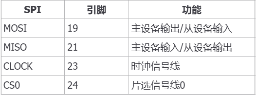
2 SPI Board Interfaces

SPI board interface

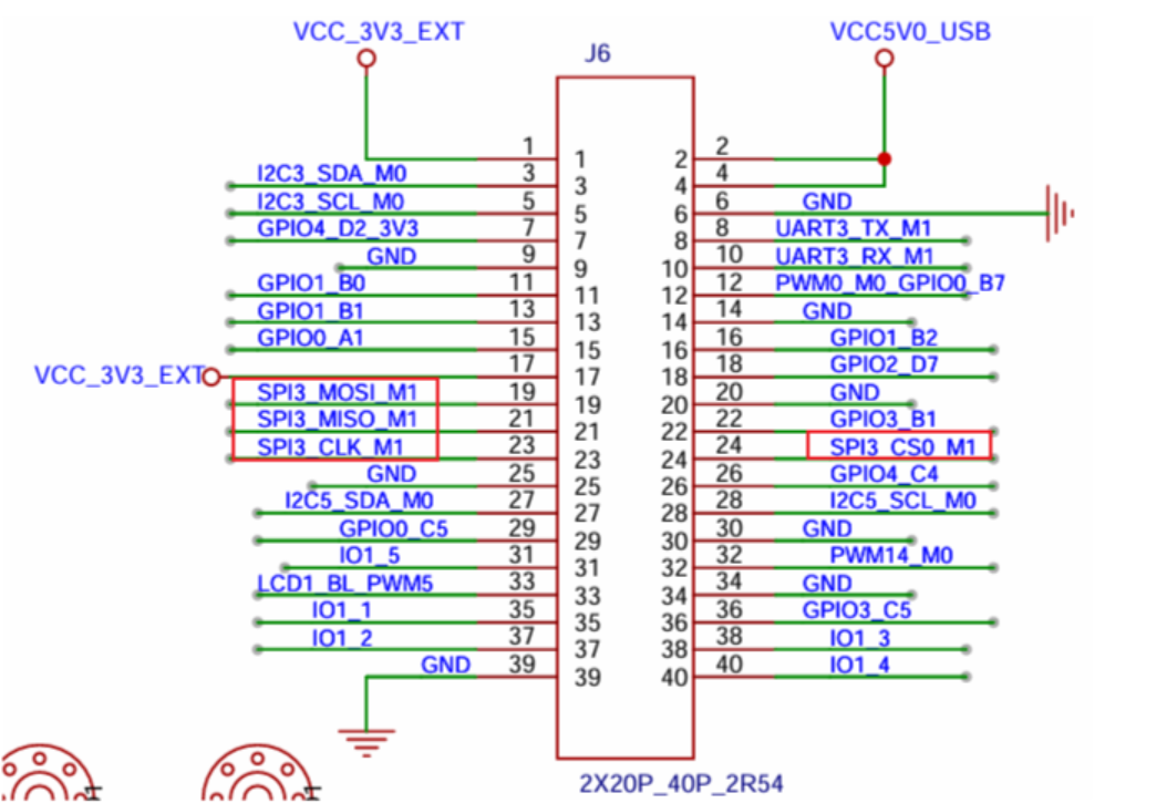
The SPI pins exposed on the board are SPI3.

SPI interface

3 SPI Usage---Command Line Method

Enter the board terminal via HDC to verify whether the spi3 device is created; run the following command from the root:

ls /dev/spi*

SPI device detection

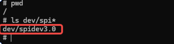
The spi3 device has been successfully mounted under the /dev directory.

3-1 Device Tree Parsing

Tips

The following file path needs to be compiled from source: out/kernel/src_tmp/linux-5.10/arch/arm64/boot/dts/rockchip/

Following the previous subsection, the basic SPI3 controller definition in rk3568.dtsi is as follows:

spi3: spi@fe640000 {
    compatible = "rockchip,rk3066-spi";
    reg = <0x0 0xfe640000 0x0 0x1000>;
    interrupts = <GIC_SPI 106 IRQ_TYPE_LEVEL_HIGH>;
    #address-cells = <1>;
    #size-cells = <0>;
    clocks = <&cru CLK_SPI3>, <&cru PCLK_SPI3>;
    clock-names = "spiclk", "apb_pclk";
    dmas = <&dmac0 26>, <&dmac0 27>;
    dma-names = "tx", "rx";
    pinctrl-names = "default", "high_speed";
    pinctrl-0 = <&spi3m0_cs0 &spi3m0_cs1 &spi3m0_pins>;
    pinctrl-1 = <&spi3m0_cs0 &spi3m0_cs1 &spi3m0_pins_hs>;
    status = "disabled";
};

3-2 Pinctrl configuration

SPI3 M1 mode pin configuration (as used in the SDK code):

spi3m1_pins: spi3m1-pins {
    rockchip,pins =
        /* spi3_clkm1 */
        <4 RK_PC2 2 &pcfg_pull_none>,
        /* spi3_misom1 */
        <4 RK_PC5 2 &pcfg_pull_none>,
        /* spi3_mosim1 */
        <4 RK_PC3 2 &pcfg_pull_none>,
};

spi3m1_cs0: spi3m1-cs0 {
rockchip,pins =
/_ spi3_cs0m1 _/
<4 RK_PC6 2 &pcfg_pull_none>;
};
spi3m1_pins_hs: spi3m1-pins {
rockchip,pins =
/_ spi3_clkm1 _/
<4 RK_PC2 2 &pcfg_pull_up_drv_level_1>;
/_ spi3_misom1 _/
<4 RK_PC5 2 &pcfg_pull_up_drv_level_1>;
/_ spi3_mosim1 _/
<4 RK_PC3 2 &pcfg_pull_up_drv_level_1>;
};

Pin assignments:

  • CLK (clock line): GPIO4_PC2, function multiplexing mode 2
  • MISO (master-in, slave-out): GPIO4_PC5, function multiplexing mode 2
  • MOSI (master-out, slave-in): GPIO4_PC3, function multiplexing mode 2
  • CS0 (chip select 0): GPIO4_PC6, function multiplexing mode 2

Finally, check the board-level file for the SPI3 specific configuration:


&spi3 {
status = "okay";
pinctrl-0 = <&spi3m1_cs0 &spi3m1_pins>;
pinctrl-1 = <&spi3m1_cs0 &spi3m1_pins_hs>;
spidev:spidev@0 {
compatible = "rockchip,spidev";
reg = <0>;
spi-max-frequency = <10000000>;
status = "okay";
};
};

3-3 Introduction to the above device tree

Pin multiplexing configurations

  • pinctrl-0: default speed mode pin configuration (uses mode m1)
  • pinctrl-1: high-speed pin configuration (enhanced drive capability)

spidev device configuration

  • compatible = "rockchip,spidev": use Rockchip's generic SPI device driver
  • reg = <0>: device address 0 (corresponding to CS0)
  • spi-max-frequency = <10000000>: maximum SPI clock frequency is 10 MHz

4 SPI Usage --- NAPI Method

Data path

hap package: \05-Development Materials\01-OpenHarmony Development Materials\Peripheral Test APP\HAP\SPI_TEST.hap Projects source: \05-Development Materials\01-OpenHarmony Development Materials\Peripheral Test APP\SRC\SPI_TEST

3-2 Application Layer SPI Operations

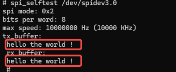
The provided SDK has already included an SPI test program for the rk3568 platform, spi_selftest. The host sends "hello the world!", shorting MOSI and MISO; the input terminal receives data to verify proper operation. This helps developers verify that the SPI controller driver works correctly and that hardware connections are proper. Simply enter the target SPI device to execute the following command:


spi_selftest /dev/spidevxx

3-3 Specific Function Demonstrations

Now test the SPI3 mounted on the board using the above commands:

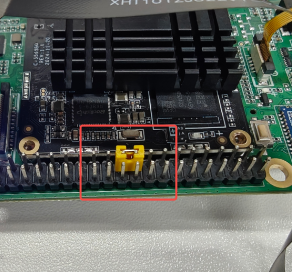
  • First, short MOSI and MISO on the board:

SPI MOSI-MISO short

  • In the terminal, enter: spi_selftest /dev/spidev3.0 to test data transmission and reception:

spi_selftest /dev/spidev3.0
  • Successfully received the bytes sent:

SPI test success

  • If MOSI and MISO are not shorted, the test shows as failed:

SPI test failed

4 SPI Usage --- NAPI Method

4-1 NAPI Program Details

To extract the NAPI C function details, see the following source:


// SPI Self-test NAPI binding example
static napi_value SPI_Test(napi_env env, napi_callback_info info) {
// (function body preserved for reference)
}

4-1 Test Environment Preparation

First, connect to the development board using the HDC tool and grant read/write permissions to the system node:


mount -o remount,rw /
chmod 777 /system/bin/spi_selftest
chmod 777 /dev/spidev3.0

4-2 SPI Device Test APP Usage

Next, an introduction to the SPI device test APP created with NAPI:

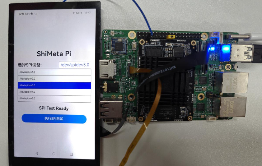
  • After entering the program, a dropdown lets you select the SPI device (the board exposes "/dev/spidev3.0" only, so select that):

  • Click the SPI test button to start the test:

SPI device selection

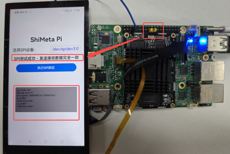
  • The test will print terminal data; if sending and receiving are matching, the test succeeds:

SPI test successful

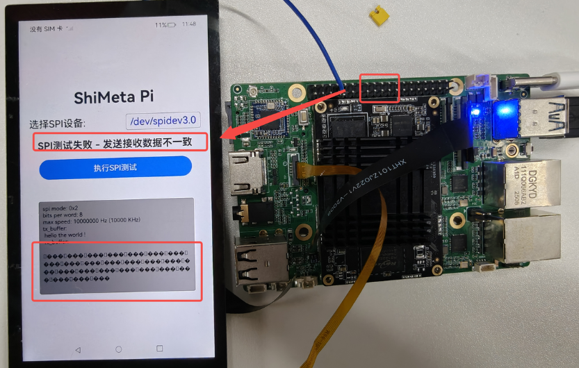
  • If the connection is broken, the test prints garbled data and reports failure:

SPI test failed

4-3 NAPI Underlying C Functions Introduction

The following C function implements NAPI; the source is included for reference:


// example C implementation for NAPI SPI_Test

Program Details

The following explains the program details:

  1. First, use napi_get_cb_info to obtain the argument from JavaScript, i.e., the device path
  2. Use napi_get_value_string_utf8 to obtain the string length and convert to a C string
  3. Create a pipe for inter-process communication; read on the read end, write on the write end
  4. Fork a child process; child executes spi_selftest with the device path; parent reads the output
  5. The rest of the code can be found in the source file

(End of file)

Edit this page on GitHub
Last Updated:
Contributors: ZSL