HOME
Shop
  • English
  • 简体中文
HOME
Shop
  • English
  • 简体中文
  • Product Series

    • FPGA+ARM

      • GM-3568JHF

        • 1. Introduction

          • About GM-3568JHF
        • 2. Quick Start

          • 00 Introduction
          • 01 Environment Setup
          • 02 Compilation Instructions
          • 03 Flashing Guide
          • 04 Debug Tools
          • 05 Software Update
          • 06 View Information
          • 07 Test Commands
          • 08 App Compilation
          • 09 Source Code Acquisition
        • 3. Peripherals and Interfaces

          • 01 USB
          • 02 Display and Touch
          • 03 Ethernet
          • 04 WIFI
          • 05 Bluetooth
          • 06 TF-Card
          • 07 Audio
          • 08 Serial Port
          • 09 CAN
          • 10 RTC
        • 4. Application Development

          • 01 UART read and write case
          • 02 Key detection case
          • 03 LED light flashing case
          • 04 MIPI screen detection case
          • 05 Read USB device information example
          • 06 FAN Detection Case
          • 07 FPGA FSPI Communication Case
          • 08 FPGA DMA read and write case
          • 09 GPS debugging case
          • 10 Ethernet Test Cases
          • 11 RS485 reading and writing examples
          • 12 FPGA IIC read and write examples
          • 13 PN532 NFC card reader case
          • 14 TF card reading and writing case
        • 5. QT Development

          • 01 ARM64 cross compiler environment construction
          • 02 QT program added automatic startup service
        • 6. RKNN_NPU Development

          • 01 RK3568 NPU Overview
          • 02 Development Environment Setup
          • Run Official YOLOv5 Example
          • Model Conversion Detailed Explanation
          • Run Custom Model on Board
        • 7. FPGA Development

          • ARM and FPGA Communication
          • /fpga-arm/GM-3568JHF/FPGA/ch02-FPGA-Development-Manual.html
        • 8. Others

          • 01 Modification of the root directory file system
          • 02 System auto-start service
        • 9. Download

          • Download Resources
    • ShimetaPi

      • M4-R1

        • 1. Introduction

          • 1.1 About M4-R1
        • 2. Quick Start

          • 2.1 OpenHarmony Overview
          • 2.2 Image Burning
          • 2.3 Development Environment Preparation
          • 2.4 Hello World Application
        • 3. Application Development

          • 3.1 Getting Started

            • 3.1.1 ArkTS Language Overview
            • 3.1.2 UI Components (Part 1)
            • 3.1.3 UI Components (Part 2)
            • 3.1.4 UI Components (Part 3)
          • 3.2 Advanced

            • 3.2.1 Getting Started Guide
            • 3.2.2 Usage of Third Party Libraries
            • 3.2.3 Deployment of the Application
            • 3.2.4 Factory Reset
            • 3.2.5 System Debug
            • 3.2.6 APP Stability Testing
            • 3.2.7 Application Testing
          • 3.3 Getting Docs

            • 3.3.1 Official Website Information
          • 3.4 Development Instructions

            • 3.4.1 Full SDK
            • 3.4.2 Introduction of Third Party Libraries
            • 3.4.3 Introduction of HDC Tool
            • 3.4.4 Restore Factory Mode
            • 3.4.5 Update System API
          • 3.5 First Application

            • 3.5.1 First ArkTS App
          • 3.6 Application Demo

            • 3.6.1 UART Tool
            • 3.6.2 Graphics Tablet
            • 3.6.3 Digital Clock
            • 3.6.4 WIFI Tool
        • 4. Device Development

          • 4.1 Ubuntu Environment Development

            • 4.1.1 Environment Setup
            • 4.1.2 Download Source Code
            • 4.1.3 Compile Source Code
          • 4.2 Using DevEco Device Tool

            • 4.2.1 Tool Introduction
            • 4.2.2 Environment Construction
            • 4.2.3 Import SDK
            • 4.2.4 Function Introduction
        • 5. Peripherals and Interfaces

          • 5.1 Raspberry Pi Interfaces
          • 5.2 GPIO Interface
          • 5.3 I2C Interface
          • 5.4 SPI Communication
          • 5.5 PWM Control
          • 5.6 Serial Port Communication
          • 5.7 TF Card Slot
          • 5.8 Display Screen
          • 5.9 Touch Screen
          • 5.10 Audio
          • 5.11 RTC
          • 5.12 Ethernet
          • 5.13 M.2
          • 5.14 MINI PCIE
          • 5.15 Camera
          • 5.16 WIFI BT
          • 5.17 HAT
        • 6. FAQ

          • 6.1 Download Link
      • M5-R1

        • 1. Introduction

          • M5-R1 Development Documentation
        • 2. Quick Start

          • OpenHarmony Overview
          • Image Burning
          • Development Environment Preparation
          • Hello World Application and Deployment
        • 3. Peripherals and Interfaces

          • 3.1 Raspberry Pi Interfaces
          • 3.2 GPIO Interface
          • 3.3 I2C Interface
          • 3.4 SPI Communication
          • 3.5 PWM Control
          • 3.6 Serial Port Communication
          • 3.7 TF Card Slot
          • 3.8 Display Screen
          • 3.9 Touch Screen
          • 3.10 Audio
          • 3.11 RTC
          • 3.12 Ethernet
          • 3.13 M.2
          • 3.14 MINI PCIE
          • 3.15 Camera
          • 3.16 WIFI BT
          • 3.17 HAT
        • 4. Application Development

          • 4.1 Getting Started

            • 4.1.1 ArkTS Language Overview
            • 4.1.2 UI Components (Part 1)
            • 4.1.3 UI Components (Part 2)
            • 4.1.4 UI Components (Part 3)
          • 4.2 Advanced

            • 4.2.1 Getting Started Guide
            • 4.2.2 Usage of Third Party Libraries
            • 4.2.3 Deployment of the Application
            • 4.2.4 Factory Reset
            • 4.2.5 System Debug
            • 4.2.6 APP Stability Testing
            • 4.2.7 Application Testing
        • 5. Device Development

          • 5.1 Environment Setup
          • 5.2 Download Source Code
          • 5.3 Compile Source Code
        • 6. Download

          • Data Download
    • OpenHarmony

      • SC-3568HA

        • 1. Introduction

          • 1.1 About SC-3568HA
        • 2. Quick Start

          • 2.1 OpenHarmony Overview
          • 2.2 Image Burning
          • 2.3 Development Environment Preparation
          • 2.4 Hello World Application
        • 3. Application Development

          • 3.1 ArkUI

            • 3.1.1 ArkTS Language Overview
            • 3.1.2 UI Components (Part 1)
            • 3.1.3 UI Components (Part 2)
            • 3.1.4 UI Components (Part 3)
          • 3.2 Advanced

            • 3.2.1 Getting Started Guide
            • 3.2.2 Usage of Third Party Libraries
            • 3.2.3 Deployment of the Application
            • 3.2.4 Factory Reset
            • 3.2.5 System Debug
            • 3.2.6 APP Stability Testing
            • 3.2.7 Application Testing
        • 4. Device Development

          • 4.1 Environment Setup
          • 4.2 Download Source Code
          • 4.3 Compile Source Code
        • 5. Peripherals and Interfaces

          • 5.1 Raspberry Pi Interfaces
          • 5.2 GPIO Interface
          • 5.3 I2C Interface
          • 5.4 SPI Communication
          • 5.5 PWM Control
          • 5.6 Serial Port Communication
          • 5.7 TF Card Slot
          • 5.8 Display Screen
          • 5.9 Touch Screen
          • 5.10 Audio
          • 5.11 RTC
          • 5.12 Ethernet
          • 5.13 M.2
          • 5.14 MINI PCIE
          • 5.15 Camera
          • 5.16 WIFI BT
          • 5.17 HAT
        • 6. FAQ

          • 6.1 Download Link
      • M-K1HSE

        • 1. Introduction

          • 1.1 Product Introduction
        • 2. Quick Start

          • 2.1 Debug Tool Installation
          • 2.2 Development Environment Setup
          • 2.3 Source Code Download
          • 2.4 Build Instructions
          • 2.5 Flashing Guide
          • 2.6 APT Update Sources
          • 2.7 View Board Info
          • 2.8 CLI LED and Key Test
          • 2.9 GCC Build Programs
        • 3. Application Development

          • 3.1 Basic Application Development

            • 3.1.1 Development Environment Preparation
            • 3.1.2 First Application HelloWorld
            • 3.1.3 Develop HAR Package
          • 3.2 Peripheral Application Cases

            • 3.2.1 UART Read/Write
            • 3.2.2 Key Demo
            • 3.2.3 LED Flash
        • 4. Peripherals and Interfaces

          • 4.1 Standard Peripherals

            • 4.1.1 USB
            • 4.1.2 Display and Touch
            • 4.1.3 Ethernet
            • 4.1.4 WIFI
            • 4.1.5 Bluetooth
            • 4.1.6 TF Card
            • 4.1.7 Audio
            • 4.1.8 Serial Port
            • 4.1.9 CAN
            • 4.1.10 RTC
          • 4.2 Interfaces

            • 4.2.1 Audio
            • 4.2.2 RS485
            • 4.2.3 Display
            • 4.2.4 Touch
        • 5. System Customization Development

          • 5.1 System Porting
          • 5.2 System Customization
          • 5.3 Driver Development
          • 5.4 System Debugging
          • 5.5 OTA Upgrade
        • 6. Download

          • 6.1 Download
    • EVS-Camera

      • CF-NRS1

        • 1. Introduction

          • 1.1 About CF-NRS1
          • 1.2 Event-Based Concepts
          • 1.3 Quick Start
          • 1.4 Resources
        • 2. Development

          • 2.1 Development Overview

            • 2.1.1 Shimetapi Hybrid Camera SDK Introduction
          • 2.2 Environment & API

            • 2.2.1 Environment Overview
            • 2.2.2 Development API Overview
          • 2.3 Linux Development

            • 2.3.1 Linux SDK Introduction
            • 2.3.2 Linux SDK API
            • 2.3.3 Linux Algorithm
            • 2.3.4 Linux Algorithm API
          • 2.4 Service & Web

            • 2.4.1 EVS Server
            • 2.4.2 Time Server
            • 2.4.3 EVS Web
        • 3. Download

          • 3.1 Download
        • 4. Common Problems

          • 4.1 Common Problems
      • CF-CRA2

        • 1. Introduction

          • 1.1 About CF-CRA2
        • 2. Download

          • 2.1 Download
      • EVS Module

        • 1. Related Concepts
        • 2. Hardware Preparation and Environment Configuration
        • 3. Example Program User Guide
        • Resources Download
    • AI-model

      • 1684XB-32T

        • 1. Introduction

          • AIBOX-1684XB-32 Introduction
        • 2. Quick Start

          • First time use
          • Network Configuration
          • Disk usage
          • Memory allocation
          • Fan Strategy
          • Firmware Upgrade
          • Cross-Compilation
          • Model Quantization
        • 3. Application Development

          • 3.1 Development Introduction

            • Sophgo SDK Development
            • SOPHON-DEMO Introduction
          • 3.2 Large Language Models

            • Deploying Llama3 Example
            • /ai-model/AIBOX-1684XB-32/application-development/LLM/Sophon_LLM_api_server-Development-AIBOX-1684XB-32.html
            • /ai-model/AIBOX-1684XB-32/application-development/LLM/MiniCPM-V-2_6-AIBOX-1684XB-32.html
            • /ai-model/AIBOX-1684XB-32/application-development/LLM/Qwen-2-5-VL-demo-Development-AIBOX-1684XB-32.html
            • /ai-model/AIBOX-1684XB-32/application-development/LLM/Qwen-3-chat-demo-Development-AIBOX-1684XB-32.html
            • /ai-model/AIBOX-1684XB-32/application-development/LLM/Qwen3-Qwen Agent-MCP.html
            • /ai-model/AIBOX-1684XB-32/application-development/LLM/Qwen3-langchain-AI Agent.html
          • 3.3 Deep Learning

            • ResNet (Image Classification)
            • LPRNet (License Plate Recognition)
            • SAM (Universal Image Segmentation Foundation Model)
            • YOLOv5 (Object Detection)
            • OpenPose (Human Keypoint Detection)
            • PP-OCR (Optical Character Recognition)
        • 4. Download

          • Resource Download
      • 1684X-416T

        • 1. Introduction

          • AIBOX-1684X-416 Introduction
        • 2. Demo Simple Operation Guide

          • Simple instructions for using shimeta smart monitoring demo
      • RDK-X5

        • 1. Introduction

          • RDK-X5 Hardware Introduction
        • 2. Quick Start

          • RDK-X5 Quick Start
        • 3. Application Development

          • 3.1 AI Online Model Development

            • AI Online Development - Experiment01
            • AI Online Development - Experiment02
            • AI Online Development - Experiment03
            • AI Online Development - Experiment04
            • AI Online Development - Experiment05
            • AI Online Development - Experiment06
          • 3.2 Large Language Models (Voice)

            • Voice LLM Application - Experiment01
            • Voice LLM Application - Experiment02
            • Voice LLM Application - Experiment03
            • Voice LLM Application - Experiment04
            • Voice LLM Application - Experiment05
            • Voice LLM Application - Experiment06
          • 3.3 40pin-IO Development

            • 40pin IO Development - Experiment01
            • 40pin IO Development - Experiment02
            • 40pin IO Development - Experiment03
            • 40pin IO Development - Experiment04
            • 40pin IO Development - Experiment05
            • 40pin IO Development - Experiment06
            • 40pin IO Development - Experiment07
          • 3.4 USB Module Development

            • USB Module Usage - Experiment01
            • USB Module Usage - Experiment02
          • 3.5 Machine Vision

            • Machine Vision Technology Development - Experiment01
            • Machine Vision Technology Development - Experiment02
            • Machine Vision Technology Development - Experiment03
            • Machine Vision Technology Development - Experiment04
          • 3.6 ROS2 Base Development

            • ROS2 Basic Development - Experiment01
            • ROS2 Basic Development - Experiment02
            • ROS2 Basic Development - Experiment03
            • ROS2 Basic Development - Experiment04
      • RDK-S100

        • 1. Introduction

          • 1.1 About RDK-S100
        • 2. Quick Start

          • 2.1 First Use
        • 3. Application Development

          • 3.1 AI Online Model Development

            • 3.1.1 Volcano Engine Doubao AI
            • 3.1.2 Image Analysis
            • 3.1.3 Multimodal Visual Analysis
            • 3.1.4 Multimodal Image Comparison
            • 3.1.5 Multimodal Document Analysis
            • 3.1.6 Camera AI Vision Analysis
          • 3.2 Large Language Models

            • 3.2.1 Speech Recognition
            • 3.2.2 Voice Conversation
            • 3.2.3 Multimodal Image Analysis
            • 3.2.4 Multimodal Image Comparison
            • 3.2.5 Multimodal Document Analysis
            • 3.2.6 Multimodal Vision Application
          • 3.3 40pin-IO Development

            • 3.3.1 GPIO Output LED Blink
            • 3.3.2 GPIO Input
            • 3.3.3 Key Control LED
            • 3.3.4 PWM Output
            • 3.3.5 Serial Output
            • 3.3.6 I2C Experiment
          • 3.4 USB Module Development

            • 3.4.1 USB Voice Module
            • 3.4.2 Sound Source Localization
          • 3.5 Machine Vision

            • 3.5.1 USB Camera
            • 3.5.2 Image Processing Basics
            • 3.5.3 Object Detection
            • 3.5.4 Image Segmentation
          • 3.6 ROS2 Base Development

            • 3.6.1 Environment Setup
            • 3.6.2 Create and Build Workspace
            • 3.6.3 ROS2 Topic Communication
            • 3.6.4 ROS2 Camera Application
    • Core-Board

      • C-3568BQ

        • 1. Introduction

          • C-3568BQ Introduction
      • C-3588LQ

        • 1. Introduction

          • C-3588LQ Introduction
      • GC-3568JBAF

        • 1. Introduction

          • GC-3568JBAF Introduction
      • C-K1BA

        • 1. Introduction

          • C-K1BA Introduction

10 UART Communication

1 UART Introduction

For basic concepts of UART communication, please refer to: https://zhuanlan.zhihu.com/p/657771076 Rockchip UART (Universal Asynchronous Receiver/Transmitter) is based on the 16550A serial standard, with the complete module supporting the following features:

  • Supports 5, 6, 7, 8 bits data length.
  • Supports 1, 1.5, 2 bits stop bits.
  • Supports odd parity and even parity, does not support mark parity and space parity.
  • Supports receive FIFO and transmit FIFO, generally 32 bytes or 64 bytes.
  • Supports up to 4M baud rate, actual supported baud rate needs to coordinate with chip clock division strategy.
  • Supports interrupt transfer mode and DMA transfer mode.
  • Supports hardware automatic flow control, RTS+CTS.

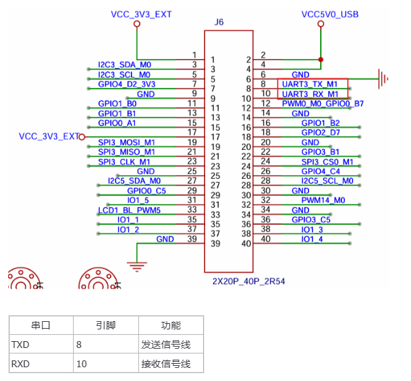
2 UART Board Interface

UART Board Interface

3 UART Usage - Command Line Method

3.1 Device Tree Parsing

Tips

The file path below: out/kernel/src_tmp/linux-5.10/arch/arm64/boot/dts/rockchip/ requires compiling the source code first.

Basic definition layer (rk3568.dtsi):

uart3: serial@fe670000 {
    compatible = "rockchip,rk3568-uart", "snps,dw-apb-uart";
    reg = <0x0 0xfe670000 0x0 0x100>;
    interrupts = <GIC_SPI 119 IRQ_TYPE_LEVEL_HIGH>;
    clocks = <&cru SCLK_UART3>, <&cru PCLK_UART3>;
    clock-names = "baudclk", "apb_pclk";
    reg-shift = <2>;
    reg-io-width = <4>;
    dmas = <&dmac0 6>, <&dmac0 7>;
    pinctrl-names = "default";
    pinctrl-0 = <&uart3m0_xfer>;
    status = "disabled";
};

Let's parse some basic properties:

  • compatible: Specifies compatibility, supports RK3568 UART and standard DW APB UART
  • reg: Register address range (0xfe670000-0xfe6700ff)
  • interrupts: Interrupt number 119, high-level trigger
  • clocks: Baud rate clock (SCLK_UART3) and APB clock (PCLK_UART3)
  • dmas: DMA channels 6 (TX) and 7 (RX)
  • pinctrl-0: Uses uart3m0_xfer pin group by default
  • status: Disabled by default

Pin configuration layer (rk3568-pinctrl.dtsi), where UART3 provides 2 pin configuration modes:

uart3m0_xfer: uart3m0-xfer {
    rockchip,pins =
        /* uart3_rxm0 */
        <1 RK_PA0 2 &pcfg_pull_up>,
        /* uart3_txm0 */
        <1 RK_PA1 2 &pcfg_pull_up>
};

uart3m1_xfer: uart3m1-xfer {
    rockchip,pins =
        /* uart3_rxm1 */
        <3 RK_PC0 4 &pcfg_pull_up>,
        /* uart3_txm1 */
        <3 RK_PB7 4 &pcfg_pull_up>
};
  • uart3m0_xfer: Pin group 1, uses PA0 as RX, PA1 as TX
  • uart3m1_xfer: Pin group 2, uses PC0 as RX, PB7 as TX

Board-level configuration layer (rk3568-toybrick-x0.dtsi):

&uart3 {
    status = "okay";
    pinctrl-names = "default";
    pinctrl-0 = <&uart3m1_xfer>;
};
  • &uart3: References the uart3 node in the basic definition
  • status = "okay": Enables the UART3 controller
  • pinctrl-0: Selects M1 mode pins (GPIO3_C0/GPIO3_B7)

3.2 UART Testing Method at Application Layer

In the past, when developing and debugging microcontrollers, we often used USB to serial modules from Qin Heng Electronics (CH340 series). In addition, there are common FT232RL USB to serial chips. The test this time uses a USB to serial module equipped with the FT232RL chip. There is no difference in usage between them. In actual use, we only need to connect the module's TX and RX to the board's RX and TX.

USB to Serial Module

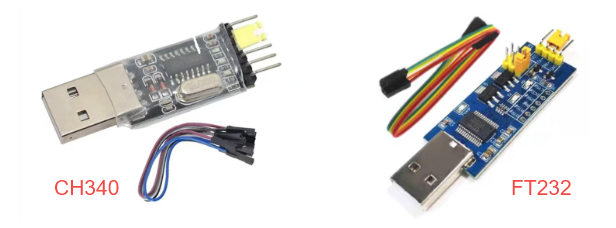
In this experiment, we still choose this method to communicate with the board via USB for UART.

As before, the driver files are placed in the /dev directory. Execute the command:

ls /dev/tty*

You can view all terminal devices as follows:

UART Device List

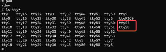
Among them, the tty prefix is for virtual terminals, and the ttyS prefix is for the serial terminal that this section needs to study.

(ttyS3 is UART3, ttyS8 is UART8 (this serial port is occupied by the Bluetooth module))

Busybox is a single executable that integrates hundreds of common Linux commands, among which stty is the abbreviation for "set tty" and is a command specifically used to change and print terminal line settings.

Common commands are as follows:

View Port

busybox stty -F /dev/ttySx     //ttyS is the specific port to view

Set Baud Rate

busybox stty -F /dev/ttyS3 baudrate

Set Baud Rate to 9600, 8 Data Bits, 1 Stop Bit, No Parity

busybox stty -F /dev/ttyS3 9600 cs8 -cstopb -parenb

Disable Hardware Flow Control

busybox stty -F /dev/ttyS3 -crtscts

microcom is a component of BusyBox, whose core function is to open a specified serial device and implement data reception.

Run Serial Port at Baud Rate 115200

microcom -s 115200 /dev/ttyS3

3.2 Specific Function Demonstration

Use the ssty tool to query the board serial port UART3 parameters:

busybox stty -F /dev/ttyS3
UART Parameter Query

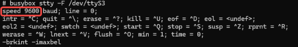
Use the ssty tool to modify the serial port baud rate to 115200, where ispeed is the input rate and ospeed is the output rate:

busybox stty -F /dev/ttyS3 ispeed 115200 ospeed 115200
UART Baud Rate Setting

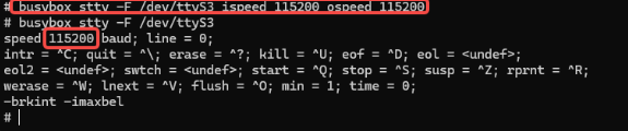
(Note: Each time the device restarts, the baud rate needs to be set again. After restart, it defaults to baud rate 9600)

Note

Serial tool download link and path: https://pan.baidu.com/s/1ZUn2BNg-Sb6M-fWhDqAFMw?pwd=smcc Extraction code: smcc ShimetaPi OpenHarmony Resources>02-Software Tools>Rockchip>OpenHarmony>Serial Tools>sscom5.13.1.exe

After configuring the serial debugging assistant according to the above settings, use the following commands on the board side to test whether serial data sending is successful:

# Execute the following commands on the board terminal
# Use echo command to write strings "Hello!" and "OpenHarmony!" to the terminal device file
echo Hello! > /dev/ttyS3
echo "OpenHarmony" > /dev/ttyS3
# The serial debugging assistant on PC will receive the content
UART Send Test

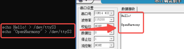
The PC side successfully received the data as shown in the figure. The board sending data is normal.

Next, test whether the board's serial port can receive data normally by sending data from the PC side.

Use the microcom tool mentioned above, execute the following commands on the board terminal to connect to the serial device ttyS3 and perform bidirectional communication. At this time, the microcom command will wait for serial data and display the received data on the terminal:

microcom -s 115200 /dev/ttyS3
UART Receive Test

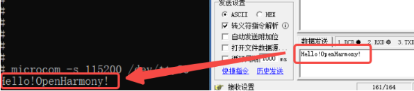
The board terminal successfully displays the received data. The PC side sends data, the board successfully receives the data, and the board receives data normally.

4. UART Usage - NAPI Method

Resource Path

HAP package: \05-Development Resources\01-OpenHarmony Development Resources\Peripheral Test APP\HAP\UART_TEST.hap

Project source code: \05-Development Resources\01-OpenHarmony Development Resources\Peripheral Test APP\SRC\UART_TEST

Here we use reading and writing to the system node /dev/ttyS3 to build NAPI.

4-1 Test Environment Preparation

First, set permissions for the /dev/ttyS3 node:

chmod 777 /dev/ttyS3             //path

4-2 Test Program Usage Introduction

Below is our serial port test program. The basic functions implemented are serial port on/off and data sending/receiving. Considering the difficulty of layout and to reduce complexity, we did not add parameter configuration functions to the program interface, but used a line of text to mark it. The C source code provided has already implemented this part of the function. Friends with ability can add it to the ets file by themselves!

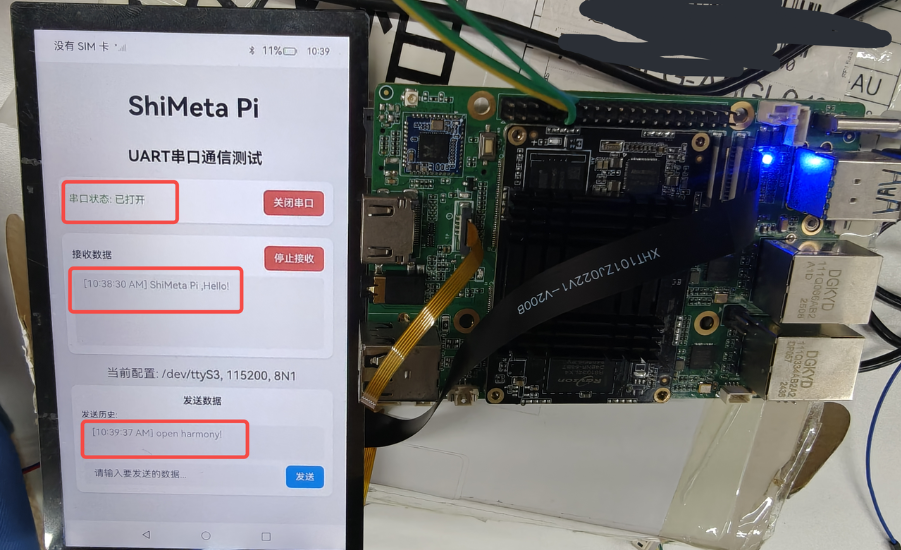
Connect the development board to the computer through the USB to TTL module. Open the application as shown in the figure below. We open the serial port.

UART App Open Serial Port

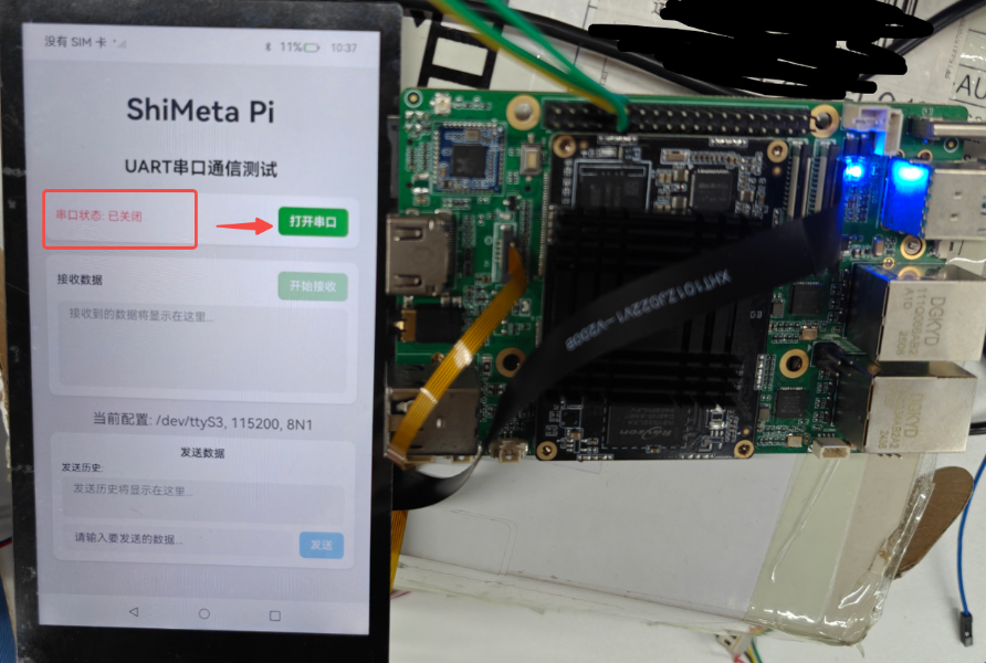
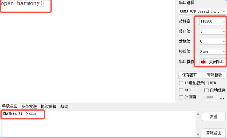
After opening the serial port, click "Start Receiving", and use the PC serial assistant to send the text "ShiMeta Pi, Hello!". The application successfully receives the text and displays it in the data receiving area.

Then send the string "open harmony!" through the application. The serial terminal also successfully receives the data, as shown in the following figures:

UART Data Exchange 1UART Data Exchange 2

4-3 Test Program Code Introduction

Since the knowledge points involved have been introduced earlier, the test program napi_init.cpp code is attached below for friends in need to reference. You can also view it in the resources.

#include "napi/native_api.h"
#include <stdio.h>
#include <stdlib.h>
#include <unistd.h>
#include <fcntl.h>
#include <string.h>
#include <errno.h>
#include <termios.h>
#include <sys/ioctl.h>
#include <sys/types.h>
#include <sys/stat.h>
#include "hilog/log.h"

const int GLOBAL_RESMGR = 0xFF00;
const char *UART_TAG = "[UART]";
const char *UART_DEVICE = "/dev/ttyS3";  // Fixed use of ttyS3 serial port

// Global variables
static int uart_fd = -1;        // Serial file descriptor
static struct termios old_cfg;  // Save original configuration
static bool uart_opened = false;

// Configure serial port parameters
static int configure_uart(int fd, int baudrate, int databits, int stopbits, char parity)
{
    struct termios cfg;

    // Get current configuration
    if (tcgetattr(fd, &cfg) != 0) {
        OH_LOG_Print(LOG_APP, LOG_ERROR, GLOBAL_RESMGR, UART_TAG,
                   "Failed to get uart config: %{public}s", strerror(errno));
        return -1;
    }

    // Save original configuration
    old_cfg = cfg;

    // Clear all flags
    cfg.c_cflag &= ~CSIZE;
    cfg.c_cflag &= ~CSTOPB;
    cfg.c_cflag &= ~PARENB;
    cfg.c_cflag &= ~PARODD;

    // Set data bits
    switch (databits) {
        case 5: cfg.c_cflag |= CS5; break;
        case 6: cfg.c_cflag |= CS6; break;
        case 7: cfg.c_cflag |= CS7; break;
        case 8: cfg.c_cflag |= CS8; break;
        default: cfg.c_cflag |= CS8; break;
    }

    // Set stop bits
    if (stopbits == 2) {
        cfg.c_cflag |= CSTOPB;
    }

    // Set parity bits
    switch (parity) {
        case 'O': case 'o': // Odd parity
            cfg.c_cflag |= PARENB;
            cfg.c_cflag |= PARODD;
            break;
        case 'E': case 'e': // Even parity
            cfg.c_cflag |= PARENB;
            cfg.c_cflag &= ~PARODD;
            break;
        case 'N': case 'n': // No parity
        default:
            cfg.c_cflag &= ~PARENB;
            break;
    }

    // Set baud rate
    speed_t speed;
    switch (baudrate) {
        case 4800: speed = B4800; break;
        case 9600: speed = B9600; break;
        case 19200: speed = B19200; break;
        case 38400: speed = B38400; break;
        case 57600: speed = B57600; break;
        case 115200: speed = B115200; break;
        case 230400: speed = B230400; break;
        case 460800: speed = B460800; break;
        case 921600: speed = B921600; break;
        case 1500000: speed = B1500000; break;
        default: speed = B115200; break;
    }

    cfsetispeed(&cfg, speed);
    cfsetospeed(&cfg, speed);

    // Set control mode
    cfg.c_cflag |= CLOCAL | CREAD;

    // Set input mode
    cfg.c_iflag &= ~(IXON | IXOFF | IXANY);
    cfg.c_iflag &= ~(INLCR | ICRNL | IGNCR);

    // Set output mode
    cfg.c_oflag &= ~OPOST;

    // Set local mode
    cfg.c_lflag &= ~(ICANON | ECHO | ECHOE | ISIG);

    // Set read parameters
    cfg.c_cc[VTIME] = 0; // Non-blocking read
    cfg.c_cc[VMIN] = 0;

    // Apply configuration
    if (tcsetattr(fd, TCSANOW, &cfg) != 0) {
        OH_LOG_Print(LOG_APP, LOG_ERROR, GLOBAL_RESMGR, UART_TAG,
                   "Failed to set uart config: %{public}s", strerror(errno));
        return -1;
    }

    // Flush buffer
    tcflush(fd, TCIOFLUSH);

    return 0;
}

// Open serial port
static napi_value Open_UART(napi_env env, napi_callback_info info)
{
    napi_value result;

    // Check if serial port is already opened
    if (uart_opened) {
        OH_LOG_Print(LOG_APP, LOG_WARN, GLOBAL_RESMGR, UART_TAG,
                   "UART is already opened");
        napi_create_string_utf8(env, "UART already opened", NAPI_AUTO_LENGTH, &result);
        return result;
    }

    // Open serial device
    uart_fd = open(UART_DEVICE, O_RDWR | O_NOCTTY | O_NONBLOCK);
    if (uart_fd < 0) {
        OH_LOG_Print(LOG_APP, LOG_ERROR, GLOBAL_RESMGR, UART_TAG,
                   "Failed to open %{public}s: %{public}s", UART_DEVICE, strerror(errno));
        napi_create_string_utf8(env, "Failed to open UART device", NAPI_AUTO_LENGTH, &result);
        return result;
    }

    // Configure serial port parameters (115200, 8N1)
    if (configure_uart(uart_fd, 115200, 8, 1, 'N') != 0) {
        close(uart_fd);
        uart_fd = -1;
        napi_create_string_utf8(env, "Failed to configure UART", NAPI_AUTO_LENGTH, &result);
        return result;
    }

    uart_opened = true;
    OH_LOG_Print(LOG_APP, LOG_INFO, GLOBAL_RESMGR, UART_TAG,
               "UART opened successfully");

    napi_create_string_utf8(env, "UART opened successfully", NAPI_AUTO_LENGTH, &result);
    return result;
}

// Close serial port
static napi_value Close_UART(napi_env env, napi_callback_info info)
{
    napi_value result;

    if (!uart_opened || uart_fd < 0) {
        OH_LOG_Print(LOG_APP, LOG_WARN, GLOBAL_RESMGR, UART_TAG,
                   "UART is not opened");
        napi_create_string_utf8(env, "UART is not opened", NAPI_AUTO_LENGTH, &result);
        return result;
    }

    // Restore original configuration
    tcsetattr(uart_fd, TCSANOW, &old_cfg);

    // Close serial port
    close(uart_fd);
    uart_fd = -1;
    uart_opened = false;

    OH_LOG_Print(LOG_APP, LOG_INFO, GLOBAL_RESMGR, UART_TAG,
               "UART closed successfully");

    napi_create_string_utf8(env, "UART closed successfully", NAPI_AUTO_LENGTH, &result);
    return result;
}

// Set serial port configuration
static napi_value Set_UART_Config(napi_env env, napi_callback_info info)
{
    napi_value result;
    size_t argc = 4;
    napi_value args[4];

    // Get parameters
    napi_get_cb_info(env, info, &argc, args, nullptr, nullptr);

    if (argc < 4) {
        napi_create_string_utf8(env, "Invalid parameters", NAPI_AUTO_LENGTH, &result);
        return result;
    }

    if (!uart_opened || uart_fd < 0) {
        napi_create_string_utf8(env, "UART is not opened", NAPI_AUTO_LENGTH, &result);
        return result;
    }

    // Parse parameters
    int32_t baudrate, databits, stopbits;
    char parity_char;
    size_t parity_len;
    char parity_str[10];

    napi_get_value_int32(env, args[0], &baudrate);
    napi_get_value_int32(env, args[1], &databits);
    napi_get_value_int32(env, args[2], &stopbits);
    napi_get_value_string_utf8(env, args[3], parity_str, sizeof(parity_str), &parity_len);

    parity_char = (parity_len > 0) ? parity_str[0] : 'N';

    // Reconfigure serial port
    if (configure_uart(uart_fd, baudrate, databits, stopbits, parity_char) != 0) {
        napi_create_string_utf8(env, "Failed to configure UART", NAPI_AUTO_LENGTH, &result);
        return result;
    }

    OH_LOG_Print(LOG_APP, LOG_INFO, GLOBAL_RESMGR, UART_TAG,
               "UART configured: %{public}d-%{public}d-%{public}d-%{public}c",
               baudrate, databits, stopbits, parity_char);

    napi_create_string_utf8(env, "UART configured successfully", NAPI_AUTO_LENGTH, &result);
    return result;
}

// Send data
static napi_value Send_Data(napi_env env, napi_callback_info info)
{
    napi_value result;
    size_t argc = 1;
    napi_value args[1];

    // Get parameters
    napi_get_cb_info(env, info, &argc, args, nullptr, nullptr);

    if (argc < 1) {
        napi_create_string_utf8(env, "Invalid parameters", NAPI_AUTO_LENGTH, &result);
        return result;
    }

    if (!uart_opened || uart_fd < 0) {
        napi_create_string_utf8(env, "UART is not opened", NAPI_AUTO_LENGTH, &result);
        return result;
    }

    // Get string to send
    size_t str_len;
    napi_get_value_string_utf8(env, args[0], nullptr, 0, &str_len);

    char *send_data = (char*)malloc(str_len + 1);
    if (!send_data) {
        napi_create_string_utf8(env, "Memory allocation failed", NAPI_AUTO_LENGTH, &result);
        return result;
    }

    napi_get_value_string_utf8(env, args[0], send_data, str_len + 1, &str_len);

    // Send data
    ssize_t bytes_written = write(uart_fd, send_data, str_len);

    if (bytes_written < 0) {
        OH_LOG_Print(LOG_APP, LOG_ERROR, GLOBAL_RESMGR, UART_TAG,
                   "Failed to send data: %{public}s", strerror(errno));
        free(send_data);
        napi_create_string_utf8(env, "Failed to send data", NAPI_AUTO_LENGTH, &result);
        return result;
    }

    OH_LOG_Print(LOG_APP, LOG_INFO, GLOBAL_RESMGR, UART_TAG,
               "Sent %{public}zd bytes: %{public}s", bytes_written, send_data);

    free(send_data);
    char response[100];
    snprintf(response, sizeof(response), "Sent %zd bytes successfully", bytes_written);
    napi_create_string_utf8(env, response, NAPI_AUTO_LENGTH, &result);
    return result;
}

// Receive data
static napi_value Receive_Data(napi_env env, napi_callback_info info)
{
    napi_value result;

    if (!uart_opened || uart_fd < 0) {
        napi_create_string_utf8(env, "UART is not opened", NAPI_AUTO_LENGTH, &result);
        return result;
    }

    char buffer[1024];
    ssize_t bytes_read = read(uart_fd, buffer, sizeof(buffer) - 1);

    if (bytes_read < 0) {
        if (errno == EAGAIN || errno == EWOULDBLOCK) {
            // No data available in non-blocking mode
            napi_create_string_utf8(env, "", NAPI_AUTO_LENGTH, &result);
            return result;
        }
        OH_LOG_Print(LOG_APP, LOG_ERROR, GLOBAL_RESMGR, UART_TAG,
                   "Failed to read data: %{public}s", strerror(errno));
        napi_create_string_utf8(env, "", NAPI_AUTO_LENGTH, &result);
        return result;
    }

    if (bytes_read == 0) {
        napi_create_string_utf8(env, "", NAPI_AUTO_LENGTH, &result);
        return result;
    }

    buffer[bytes_read] = '\0';

    OH_LOG_Print(LOG_APP, LOG_INFO, GLOBAL_RESMGR, UART_TAG,
               "Received %{public}zd bytes: %{public}s", bytes_read, buffer);

    napi_create_string_utf8(env, buffer, NAPI_AUTO_LENGTH, &result);
    return result;
}

// Check serial port status
static napi_value Get_UART_Status(napi_env env, napi_callback_info info)
{
    napi_value result;

    if (uart_opened && uart_fd >= 0) {
        napi_create_string_utf8(env, "opened", NAPI_AUTO_LENGTH, &result);
    } else {
        napi_create_string_utf8(env, "closed", NAPI_AUTO_LENGTH, &result);
    }

    return result;
}

// Module initialization
EXTERN_C_START
static napi_value Init(napi_env env, napi_value exports)
{
    napi_property_descriptor desc[] = {
        { "Open_UART", nullptr, Open_UART, nullptr, nullptr, nullptr, napi_default, nullptr },
        { "Close_UART", nullptr, Close_UART, nullptr, nullptr, nullptr, napi_default, nullptr },
        { "Set_UART_Config", nullptr, Set_UART_Config, nullptr, nullptr, nullptr, napi_default, nullptr },
        { "Send_Data", nullptr, Send_Data, nullptr, nullptr, nullptr, napi_default, nullptr },
        { "Receive_Data", nullptr, Receive_Data, nullptr, nullptr, nullptr, napi_default, nullptr },
        { "Get_UART_Status", nullptr, Get_UART_Status, nullptr, nullptr, nullptr, napi_default, nullptr }
    };

    napi_define_properties(env, exports, sizeof(desc) / sizeof(desc[0]), desc);
    return exports;
}
EXTERN_C_END

static napi_module demoModule = {
    .nm_version = 1,
    .nm_flags = 0,
    .nm_filename = nullptr,
    .nm_register_func = Init,
    .nm_modname = "entry",
    .nm_priv = ((void*)0),
    .reserved = { 0 },
};

extern "C" __attribute__((constructor)) void RegisterEntryModule(void)
{
    napi_module_register(&demoModule);
}
Edit this page on GitHub
Last Updated:
Contributors: ZSL