HOME
Shop
  • English
  • 简体中文
HOME
Shop
  • English
  • 简体中文
  • Product Series

    • FPGA+ARM

      • GM-3568JHF

        • 1. Introduction

          • About GM-3568JHF
        • 2. Quick Start

          • 00 Introduction
          • 01 Environment Setup
          • 02 Compilation Instructions
          • 03 Flashing Guide
          • 04 Debug Tools
          • 05 Software Update
          • 06 View Information
          • 07 Test Commands
          • 08 App Compilation
          • 09 Source Code Acquisition
        • 3. Peripherals and Interfaces

          • 01 USB
          • 02 Display and Touch
          • 03 Ethernet
          • 04 WIFI
          • 05 Bluetooth
          • 06 TF-Card
          • 07 Audio
          • 08 Serial Port
          • 09 CAN
          • 10 RTC
        • 4. Application Development

          • 01 UART read and write case
          • 02 Key detection case
          • 03 LED light flashing case
          • 04 MIPI screen detection case
          • 05 Read USB device information example
          • 06 FAN Detection Case
          • 07 FPGA FSPI Communication Case
          • 08 FPGA DMA read and write case
          • 09 GPS debugging case
          • 10 Ethernet Test Cases
          • 11 RS485 reading and writing examples
          • 12 FPGA IIC read and write examples
          • 13 PN532 NFC card reader case
          • 14 TF card reading and writing case
        • 5. QT Development

          • 01 ARM64 cross compiler environment construction
          • 02 QT program added automatic startup service
        • 6. RKNN_NPU Development

          • 01 RK3568 NPU Overview
          • 02 Development Environment Setup
          • Run Official YOLOv5 Example
          • Model Conversion Detailed Explanation
          • Run Custom Model on Board
        • 7. FPGA Development

          • ARM and FPGA Communication
          • /fpga-arm/GM-3568JHF/FPGA/ch02-FPGA-Development-Manual.html
        • 8. Others

          • 01 Modification of the root directory file system
          • 02 System auto-start service
        • 9. Download

          • Download Resources
    • ShimetaPi

      • M4-R1

        • 1. Introduction

          • 1.1 About M4-R1
        • 2. Quick Start

          • 2.1 OpenHarmony Overview
          • 2.2 Image Burning
          • 2.3 Development Environment Preparation
          • 2.4 Hello World Application
        • 3. Application Development

          • 3.1 Getting Started

            • 3.1.1 ArkTS Language Overview
            • 3.1.2 UI Components (Part 1)
            • 3.1.3 UI Components (Part 2)
            • 3.1.4 UI Components (Part 3)
          • 3.2 Advanced

            • 3.2.1 Getting Started Guide
            • 3.2.2 Usage of Third Party Libraries
            • 3.2.3 Deployment of the Application
            • 3.2.4 Factory Reset
            • 3.2.5 System Debug
            • 3.2.6 APP Stability Testing
            • 3.2.7 Application Testing
          • 3.3 Getting Docs

            • 3.3.1 Official Website Information
          • 3.4 Development Instructions

            • 3.4.1 Full SDK
            • 3.4.2 Introduction of Third Party Libraries
            • 3.4.3 Introduction of HDC Tool
            • 3.4.4 Restore Factory Mode
            • 3.4.5 Update System API
          • 3.5 First Application

            • 3.5.1 First ArkTS App
          • 3.6 Application Demo

            • 3.6.1 UART Tool
            • 3.6.2 Graphics Tablet
            • 3.6.3 Digital Clock
            • 3.6.4 WIFI Tool
        • 4. Device Development

          • 4.1 Ubuntu Environment Development

            • 4.1.1 Environment Setup
            • 4.1.2 Download Source Code
            • 4.1.3 Compile Source Code
          • 4.2 Using DevEco Device Tool

            • 4.2.1 Tool Introduction
            • 4.2.2 Environment Construction
            • 4.2.3 Import SDK
            • 4.2.4 Function Introduction
        • 5. Peripherals and Interfaces

          • 5.1 Raspberry Pi Interfaces
          • 5.2 GPIO Interface
          • 5.3 I2C Interface
          • 5.4 SPI Communication
          • 5.5 PWM Control
          • 5.6 Serial Port Communication
          • 5.7 TF Card Slot
          • 5.8 Display Screen
          • 5.9 Touch Screen
          • 5.10 Audio
          • 5.11 RTC
          • 5.12 Ethernet
          • 5.13 M.2
          • 5.14 MINI PCIE
          • 5.15 Camera
          • 5.16 WIFI BT
          • 5.17 HAT
        • 6. FAQ

          • 6.1 Download Link
      • M5-R1

        • 1. Introduction

          • M5-R1 Development Documentation
        • 2. Quick Start

          • OpenHarmony Overview
          • Image Burning
          • Development Environment Preparation
          • Hello World Application and Deployment
        • 3. Peripherals and Interfaces

          • 3.1 Raspberry Pi Interfaces
          • 3.2 GPIO Interface
          • 3.3 I2C Interface
          • 3.4 SPI Communication
          • 3.5 PWM Control
          • 3.6 Serial Port Communication
          • 3.7 TF Card Slot
          • 3.8 Display Screen
          • 3.9 Touch Screen
          • 3.10 Audio
          • 3.11 RTC
          • 3.12 Ethernet
          • 3.13 M.2
          • 3.14 MINI PCIE
          • 3.15 Camera
          • 3.16 WIFI BT
          • 3.17 HAT
        • 4. Application Development

          • 4.1 Getting Started

            • 4.1.1 ArkTS Language Overview
            • 4.1.2 UI Components (Part 1)
            • 4.1.3 UI Components (Part 2)
            • 4.1.4 UI Components (Part 3)
          • 4.2 Advanced

            • 4.2.1 Getting Started Guide
            • 4.2.2 Usage of Third Party Libraries
            • 4.2.3 Deployment of the Application
            • 4.2.4 Factory Reset
            • 4.2.5 System Debug
            • 4.2.6 APP Stability Testing
            • 4.2.7 Application Testing
        • 5. Device Development

          • 5.1 Environment Setup
          • 5.2 Download Source Code
          • 5.3 Compile Source Code
        • 6. Download

          • Data Download
    • OpenHarmony

      • SC-3568HA

        • 1. Introduction

          • 1.1 About SC-3568HA
        • 2. Quick Start

          • 2.1 OpenHarmony Overview
          • 2.2 Image Burning
          • 2.3 Development Environment Preparation
          • 2.4 Hello World Application
        • 3. Application Development

          • 3.1 ArkUI

            • 3.1.1 ArkTS Language Overview
            • 3.1.2 UI Components (Part 1)
            • 3.1.3 UI Components (Part 2)
            • 3.1.4 UI Components (Part 3)
          • 3.2 Advanced

            • 3.2.1 Getting Started Guide
            • 3.2.2 Usage of Third Party Libraries
            • 3.2.3 Deployment of the Application
            • 3.2.4 Factory Reset
            • 3.2.5 System Debug
            • 3.2.6 APP Stability Testing
            • 3.2.7 Application Testing
        • 4. Device Development

          • 4.1 Environment Setup
          • 4.2 Download Source Code
          • 4.3 Compile Source Code
        • 5. Peripherals and Interfaces

          • 5.1 Raspberry Pi Interfaces
          • 5.2 GPIO Interface
          • 5.3 I2C Interface
          • 5.4 SPI Communication
          • 5.5 PWM Control
          • 5.6 Serial Port Communication
          • 5.7 TF Card Slot
          • 5.8 Display Screen
          • 5.9 Touch Screen
          • 5.10 Audio
          • 5.11 RTC
          • 5.12 Ethernet
          • 5.13 M.2
          • 5.14 MINI PCIE
          • 5.15 Camera
          • 5.16 WIFI BT
          • 5.17 HAT
        • 6. FAQ

          • 6.1 Download Link
      • M-K1HSE

        • 1. Introduction

          • 1.1 Product Introduction
        • 2. Quick Start

          • 2.1 Debug Tool Installation
          • 2.2 Development Environment Setup
          • 2.3 Source Code Download
          • 2.4 Build Instructions
          • 2.5 Flashing Guide
          • 2.6 APT Update Sources
          • 2.7 View Board Info
          • 2.8 CLI LED and Key Test
          • 2.9 GCC Build Programs
        • 3. Application Development

          • 3.1 Basic Application Development

            • 3.1.1 Development Environment Preparation
            • 3.1.2 First Application HelloWorld
            • 3.1.3 Develop HAR Package
          • 3.2 Peripheral Application Cases

            • 3.2.1 UART Read/Write
            • 3.2.2 Key Demo
            • 3.2.3 LED Flash
        • 4. Peripherals and Interfaces

          • 4.1 Standard Peripherals

            • 4.1.1 USB
            • 4.1.2 Display and Touch
            • 4.1.3 Ethernet
            • 4.1.4 WIFI
            • 4.1.5 Bluetooth
            • 4.1.6 TF Card
            • 4.1.7 Audio
            • 4.1.8 Serial Port
            • 4.1.9 CAN
            • 4.1.10 RTC
          • 4.2 Interfaces

            • 4.2.1 Audio
            • 4.2.2 RS485
            • 4.2.3 Display
            • 4.2.4 Touch
        • 5. System Customization Development

          • 5.1 System Porting
          • 5.2 System Customization
          • 5.3 Driver Development
          • 5.4 System Debugging
          • 5.5 OTA Upgrade
        • 6. Download

          • 6.1 Download
    • EVS-Camera

      • CF-NRS1

        • 1. Introduction

          • 1.1 About CF-NRS1
          • 1.2 Event-Based Concepts
          • 1.3 Quick Start
          • 1.4 Resources
        • 2. Development

          • 2.1 Development Overview

            • 2.1.1 Shimetapi Hybrid Camera SDK Introduction
          • 2.2 Environment & API

            • 2.2.1 Environment Overview
            • 2.2.2 Development API Overview
          • 2.3 Linux Development

            • 2.3.1 Linux SDK Introduction
            • 2.3.2 Linux SDK API
            • 2.3.3 Linux Algorithm
            • 2.3.4 Linux Algorithm API
          • 2.4 Service & Web

            • 2.4.1 EVS Server
            • 2.4.2 Time Server
            • 2.4.3 EVS Web
        • 3. Download

          • 3.1 Download
        • 4. Common Problems

          • 4.1 Common Problems
      • CF-CRA2

        • 1. Introduction

          • 1.1 About CF-CRA2
        • 2. Download

          • 2.1 Download
      • EVS Module

        • 1. Related Concepts
        • 2. Hardware Preparation and Environment Configuration
        • 3. Example Program User Guide
        • Resources Download
    • AI-model

      • 1684XB-32T

        • 1. Introduction

          • AIBOX-1684XB-32 Introduction
        • 2. Quick Start

          • First time use
          • Network Configuration
          • Disk usage
          • Memory allocation
          • Fan Strategy
          • Firmware Upgrade
          • Cross-Compilation
          • Model Quantization
        • 3. Application Development

          • 3.1 Development Introduction

            • Sophgo SDK Development
            • SOPHON-DEMO Introduction
          • 3.2 Large Language Models

            • Deploying Llama3 Example
            • /ai-model/AIBOX-1684XB-32/application-development/LLM/Sophon_LLM_api_server-Development-AIBOX-1684XB-32.html
            • /ai-model/AIBOX-1684XB-32/application-development/LLM/MiniCPM-V-2_6-AIBOX-1684XB-32.html
            • /ai-model/AIBOX-1684XB-32/application-development/LLM/Qwen-2-5-VL-demo-Development-AIBOX-1684XB-32.html
            • /ai-model/AIBOX-1684XB-32/application-development/LLM/Qwen-3-chat-demo-Development-AIBOX-1684XB-32.html
            • /ai-model/AIBOX-1684XB-32/application-development/LLM/Qwen3-Qwen Agent-MCP.html
            • /ai-model/AIBOX-1684XB-32/application-development/LLM/Qwen3-langchain-AI Agent.html
          • 3.3 Deep Learning

            • ResNet (Image Classification)
            • LPRNet (License Plate Recognition)
            • SAM (Universal Image Segmentation Foundation Model)
            • YOLOv5 (Object Detection)
            • OpenPose (Human Keypoint Detection)
            • PP-OCR (Optical Character Recognition)
        • 4. Download

          • Resource Download
      • 1684X-416T

        • 1. Introduction

          • AIBOX-1684X-416 Introduction
        • 2. Demo Simple Operation Guide

          • Simple instructions for using shimeta smart monitoring demo
      • RDK-X5

        • 1. Introduction

          • RDK-X5 Hardware Introduction
        • 2. Quick Start

          • RDK-X5 Quick Start
        • 3. Application Development

          • 3.1 AI Online Model Development

            • AI Online Development - Experiment01
            • AI Online Development - Experiment02
            • AI Online Development - Experiment03
            • AI Online Development - Experiment04
            • AI Online Development - Experiment05
            • AI Online Development - Experiment06
          • 3.2 Large Language Models (Voice)

            • Voice LLM Application - Experiment01
            • Voice LLM Application - Experiment02
            • Voice LLM Application - Experiment03
            • Voice LLM Application - Experiment04
            • Voice LLM Application - Experiment05
            • Voice LLM Application - Experiment06
          • 3.3 40pin-IO Development

            • 40pin IO Development - Experiment01
            • 40pin IO Development - Experiment02
            • 40pin IO Development - Experiment03
            • 40pin IO Development - Experiment04
            • 40pin IO Development - Experiment05
            • 40pin IO Development - Experiment06
            • 40pin IO Development - Experiment07
          • 3.4 USB Module Development

            • USB Module Usage - Experiment01
            • USB Module Usage - Experiment02
          • 3.5 Machine Vision

            • Machine Vision Technology Development - Experiment01
            • Machine Vision Technology Development - Experiment02
            • Machine Vision Technology Development - Experiment03
            • Machine Vision Technology Development - Experiment04
          • 3.6 ROS2 Base Development

            • ROS2 Basic Development - Experiment01
            • ROS2 Basic Development - Experiment02
            • ROS2 Basic Development - Experiment03
            • ROS2 Basic Development - Experiment04
      • RDK-S100

        • 1. Introduction

          • 1.1 About RDK-S100
        • 2. Quick Start

          • 2.1 First Use
        • 3. Application Development

          • 3.1 AI Online Model Development

            • 3.1.1 Volcano Engine Doubao AI
            • 3.1.2 Image Analysis
            • 3.1.3 Multimodal Visual Analysis
            • 3.1.4 Multimodal Image Comparison
            • 3.1.5 Multimodal Document Analysis
            • 3.1.6 Camera AI Vision Analysis
          • 3.2 Large Language Models

            • 3.2.1 Speech Recognition
            • 3.2.2 Voice Conversation
            • 3.2.3 Multimodal Image Analysis
            • 3.2.4 Multimodal Image Comparison
            • 3.2.5 Multimodal Document Analysis
            • 3.2.6 Multimodal Vision Application
          • 3.3 40pin-IO Development

            • 3.3.1 GPIO Output LED Blink
            • 3.3.2 GPIO Input
            • 3.3.3 Key Control LED
            • 3.3.4 PWM Output
            • 3.3.5 Serial Output
            • 3.3.6 I2C Experiment
          • 3.4 USB Module Development

            • 3.4.1 USB Voice Module
            • 3.4.2 Sound Source Localization
          • 3.5 Machine Vision

            • 3.5.1 USB Camera
            • 3.5.2 Image Processing Basics
            • 3.5.3 Object Detection
            • 3.5.4 Image Segmentation
          • 3.6 ROS2 Base Development

            • 3.6.1 Environment Setup
            • 3.6.2 Create and Build Workspace
            • 3.6.3 ROS2 Topic Communication
            • 3.6.4 ROS2 Camera Application
    • Core-Board

      • C-3568BQ

        • 1. Introduction

          • C-3568BQ Introduction
      • C-3588LQ

        • 1. Introduction

          • C-3588LQ Introduction
      • GC-3568JBAF

        • 1. Introduction

          • GC-3568JBAF Introduction
      • C-K1BA

        • 1. Introduction

          • C-K1BA Introduction

17 WIFI & BT

1 WIFI & BT Introduction

1.1 WIFI

WiFi (Wireless Fidelity) is a wireless communication technology based on IEEE 802.11 standards. Its core function is to connect devices to LAN (Local Area Network) wirelessly. Over the years, WiFi has almost been the first choice for high-speed wireless communication under short-distance conditions. It has two frequency bands available: 2.4GHz and 5GHz. It is commonly used for video streaming, OTA upgrades, etc. The communication speed is significantly higher than Bluetooth.

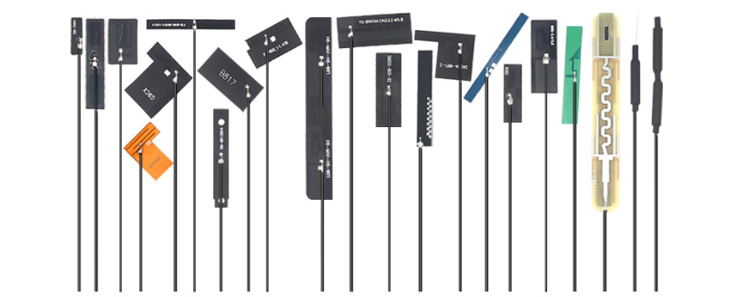
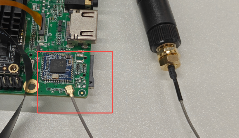
On hardware, it typically uses SDIO interface to communicate with the main controller chip. When used, it needs to be paired with an antenna to receive and transmit electromagnetic wave signals. Our embedded board generally uses external antennas, as shown in the figure:

Embedded Board External Antenna

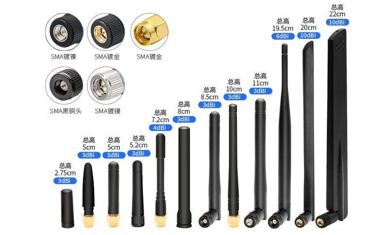
For routers and other devices with high communication requirements, the antennas used are generally like this:

Router Antenna

Some friends may be curious. In the past, feature phones with large antennas could be seen. Starting from touchscreen phones, it seems you can't see the existence of antennas anymore. Actually, in the early days, they were integrated into the phone's frame, or the phone's frame itself was the antenna. With the high integration of circuits, antenna sizes have become smaller and smaller. We can observe our own phones. The small strips on the frame are actually antennas responsible for various functions (WiFi, Bluetooth, GPS, GMS, etc.).

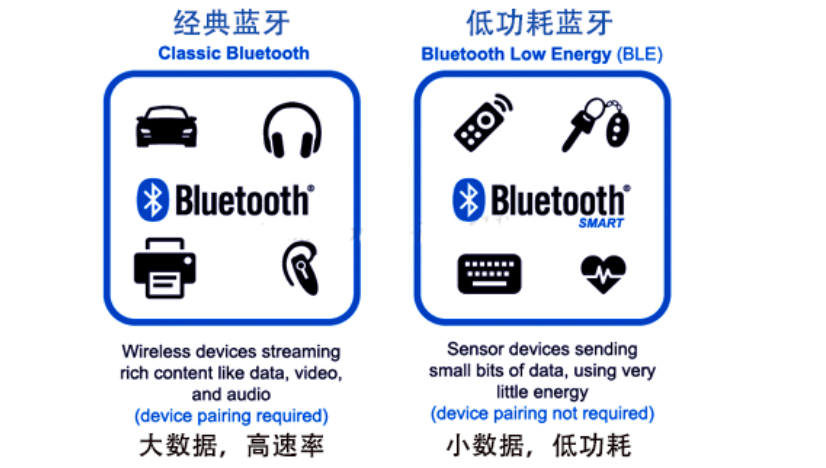
1.2 Classic Bluetooth (SPP) and Bluetooth Low Energy (BLE)

Regarding classic Bluetooth and Bluetooth Low Energy, you can refer to my summary table below:

Comparison ItemBLE (Bluetooth Low Energy)Classic Bluetooth (SPP)
Transmission DistanceShort distance, communication range is about 10 metersLonger communication distance, up to 100 meters
Transmission Rate1Mbps or lower3Mbps or higher
Bluetooth Power ConsumptionExtremely low power consumption, suitable for battery-powered devicesHigher power consumption: Classic Bluetooth is designed for speed and transmission capacity, requires continuous power supply
Hardware CostLow cost: BLE chips and modules are inexpensiveSlightly higher than BLE price
Development DifficultyLow complexity: Simple protocol stack, easy to developHigher complexity: More complex protocol stack, more difficult development
Typical ApplicationsSensors, IoT devicesBluetooth printers, high-speed data exchange (image transmission, file transfer), etc.

Bluetooth Comparison Table

Some friends may wonder what black technology BLE uses to achieve such low power consumption?

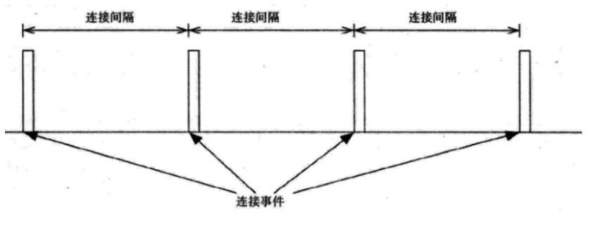
Actually, the power consumption of BLE during data transmission is not at all lower than SPP! The key to power saving is that after transmitting data with high power consumption, it enters a sleep state for a period of time, as shown in the figure below. It only transmits data when connection events occur:

BLE Connection Events Diagram

Let's look at the power consumption chart:

BLE Power Consumption Chart

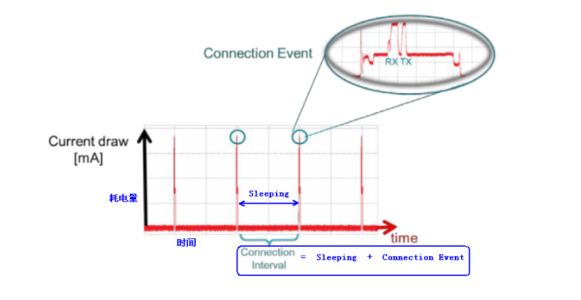
Understanding why BLE has low power consumption, we also understand why we don't use BLE when we have high data volume requirements, because most of the time it is in "sleep" state.

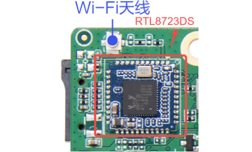
1.3 Introduction to RTL8723DS Module

RTL8723DS is an SDIO interface single-frequency single-channel Bluetooth WiFi integrated module based on the RTL8723DS chip, mainly used for smart home, IoT devices, and other embedded system designs requiring Bluetooth and WiFi functions.

This WiFi module provides SDIO interface to connect to the host processor, and provides high-speed UART interface for BT. It also has PCM interface for audio data transmission, directly connected to external audio codec through BT controller. Using 1x1 802.11b/g/n MIMO technology, theoretical WiFi throughput can reach 150Mbps.

Bluetooth supports BT2.1+EDR/BT3.0 and BT4.2, supports dual-mode Bluetooth, compatible with both BLE and SPP, meeting different development needs.

2 WIFI & BT Module Board Card Location

WIFI & BT Module Location

3 WIFI & BT Connectivity Testing

3.1 Device Tree Parsing

Tips

The file path below: out/kernel/src_tmp/linux-5.10/arch/arm64/boot/dts/rockchip/ Need to compile the source code first.

This board's WiFi and BT use SDMMC2 peripheral and UART8 respectively. Let's parse the device tree files:

Basic definition layer (rk3568.dtsi)

sdmmc2: dwmmc@fe000000 {
    compatible = "rockchip,rk3568-dw-mshc",
                 "rockchip,rk3288-dw-mshc";
    reg = <0x0 0xfe000000 0x0 0x4000>;
    interrupts = <GIC_SPI 100 IRQ_TYPE_LEVEL_HIGH>;
    max-frequency = <150000000>;
    clocks = <&cru HCLK_SDMMC2>, <&cru CLK_SDMMC2>,
             <&cru SCLK_SDMMC2_DRV>, <&cru SCLK_SDMMC2_SAMPLE>;
    clock-names = "biu", "ciu", "ciu-drive", "ciu-sample";
    fifo-depth = <0x100>;
    resets = <&cru SRST_SDMMC2>;
    reset-names = "reset";
    status = "disabled";
};
........

uart8: serial@fe6c0000 {
    compatible = "rockchip,rk3568-uart", "snps,dw-apb-uart";
    reg = <0x0 0xfe6c0000 0x0 0x100>;
    interrupts = <GIC_SPI 124 IRQ_TYPE_LEVEL_HIGH>;
    clocks = <&cru SCLK_UART8>, <&cru PCLK_UART8>;
    clock-names = "baudclk", "apb_pclk";
    reg-shift = <2>;
    reg-io-width = <4>;
    dmas = <&dmac0 16>, <&dmac0 17>;
    pinctrl-names = "default";
    pinctrl-0 = <&uart8m0_xfer>;
    status = "disabled";
};
  • sdmmc2 controller: Address 0xfe000000, supports maximum frequency 150MHz, configures clock, reset and FIFO depth
  • uart8 controller: Address 0xfe6c0000, used for Bluetooth communication, supports DMA transfer
sdmmc2 {
    sdmmc2m0_bus4: sdmmc2m0-bus4 {
        rockchip,pins =
            /* sdmmc2_d0m0 */
            <3 RK_PC6 3 &pcfg_pull_up_drv_level_2>,
            /* sdmmc2_d1m0 */
            <3 RK_PC7 3 &pcfg_pull_up_drv_level_2>,
            /* sdmmc2_d2m0 */
            <3 RK_PD0 3 &pcfg_pull_up_drv_level_2>,
            /* sdmmc2_d3m0 */
            <3 RK_PD1 3 &pcfg_pull_up_drv_level_2>;
    };

    sdmmc2m0_clk: sdmmc2m0-clk {
        rockchip,pins =
            /* sdmmc2_clkm0 */
            <3 RK_PD3 3 &pcfg_pull_up_drv_level_2>;
    };

    sdmmc2m0_cmd: sdmmc2m0-cmd {
        rockchip,pins =
            /* sdmmc2_cmdm0 */
            <3 RK_PD2 3 &pcfg_pull_up_drv_level_2>;
    };
};

uart8 {
    uart8m0_xfer: uart8m0-xfer {
        rockchip,pins =
            /* uart8_rxm0 */
            <2 RK_PC6 2 &pcfg_pull_up>,
            /* uart8_txm0 */
            <2 RK_PC5 3 &pcfg_pull_up>;
    };

    uart8m0_rtsn: uart8m0-rtsn {
        rockchip,pins =
            /* uart8m0_rtsn */
            <2 RK_PB1 3 &pcfg_pull_none>;
    };
};
  • sdio pins: GPIO3_PC6~PD3 configured as SDIO function, supports 4-bit data bus
  • uart8 pins: GPIO2_PC5/PC6 used for TX/RX, GPIO2_PB1 used for RTS control

Finally, let's look at the board-level configuration layer (excerpted from rk3568-toybrick.dtsi and rk3568-toybrick-x0.dtsi)

//Basic definition (in rk3568-toybrick.dtsi):
sdio_pwrseq: sdio-pwrseq {
    compatible = "mmc-pwrseq-simple";           // Simple MMC power sequence controller
    clocks = <&rk809 1>;                        // Use RK809 PMIC's clock output 1
    clock-names = "ext_clock";                  // External clock name
    pinctrl-names = "default";                  // Pin control state name
    pinctrl-0 = <&wifi_enable_h>;               // WiFi enable pin configuration
    post-power-on-delay-ms = <200>;             // Power-on delay 200ms
    reset-gpios = <&gpio3 RK_PD5 GPIO_ACTIVE_LOW>; // Reset GPIO, low level active
};
//Board-level override configuration (in rk3568-toybrick-x0.dtsi):
&sdio_pwrseq {
    post-power-on-delay-ms = <20>;               // Shorten delay to 20ms
    status = "okay";                            // Explicitly enable status
};
......

wireless_wlan: wireless-wlan {
    compatible = "wlan-platdata";                // WiFi platform data compatibility
    rockchip,grf = <&grf>;                      // Associate general register file
    wifi_chip_type = "rtl8723ds";               // Explicitly specify chip model
    status = "okay";                            // Enable status
};

&wireless_wlan {
    pinctrl-names = "default";                  // Pin control state
    pinctrl-0 = <&wifi_host_wake_irq>;          // Host wake interrupt pin
    WIFI,host_wake_irq = <&gpio3 RK_PD4 GPIO_ACTIVE_HIGH>; // Host wake interrupt GPIO
};
......

&wireless_bluetooth {
    compatible = "bluetooth-platdata";           // Bluetooth platform data compatibility
    clocks = <&rk809 1>;                        // Use RK809's clock 1
    clock-names = "ext_clock";                  // External clock name
    uart_rts_gpios = <&gpio2 RK_PB1 GPIO_ACTIVE_LOW>; // UART RTS control GPIO
    pinctrl-names = "default", "rts_gpio";      // Two pin states: default and RTS GPIO
    pinctrl-0 = <&uart8m0_rtsn>;               // Default state: UART8 RTS pin
    pinctrl-1 = <&uart8_gpios>;                // RTS GPIO state: GPIO mode
    BT,reset_gpio = <&gpio3 RK_PA0 GPIO_ACTIVE_HIGH>;     // Bluetooth reset GPIO
    BT,wake_gpio = <&gpio3 RK_PA2 GPIO_ACTIVE_HIGH>;      // Bluetooth wake GPIO
    BT,wake_host_irq = <&gpio3 RK_PA1 GPIO_ACTIVE_HIGH>;  // Bluetooth wake host interrupt
    status = "okay";                            // Enable status
};
......

&sdmmc2 {
    max-frequency = <150000000>;                 // Maximum operating frequency 150MHz
    supports-sdio;                               // Support SDIO protocol
    bus-width = <4>;                            // 4-bit data bus width
    disable-wp;                                 // Disable write protection detection
    cap-sd-highspeed;                           // Support SD high-speed mode
    cap-sdio-irq;                               // Support SDIO interrupt
    keep-power-in-suspend;                      // Keep power in suspend
    mmc-pwrseq = <&sdio_pwrseq>;               // Associate power sequence controller
    non-removable;                              // Non-removable device
    pinctrl-names = "default";                  // Pin control state
    pinctrl-0 = <&sdmmc2m0_bus4 &sdmmc2m0_cmd &sdmmc2m0_clk>; // Pin multiplexing configuration
    sd-uhs-sdr104;                              // Support UHS-I SDR104 mode
    status = "okay";                            // Enable status
};
......

&uart8 {
    status = "okay";                            // Enable UART8
    pinctrl-names = "default";                  // Pin control state
    pinctrl-0 = <&uart8m0_xfer &uart8m0_ctsn>; // TX/RX and CTS pin configuration
};

Due to space limitations, here are explanations for several key nodes:

  • mmc-pwrseq: Key attribute binding WiFi module to SDMMC2 interface
  • cap-sdio-irq: Enable SDIO interrupt support, improve data transfer efficiency
  • keep-power-in-suspend: Ensure WiFi module keeps power during suspend, support wake function
  • non-removable: Mark as on-board fixed device, does not support hot-plugging
  • sd-uhs-sdr104: Support high-speed transfer mode, maximum transfer rate 104MB/s
  • uart_rts_gpios: Bluetooth UART flow control signal, ensure data transfer reliability
  • Dual pin state management: Implement UART and GPIO mode switching through pinctrl-0 and pinctrl-1

3.2 WIFI & BT Connection Testing Method

Since the current version of Linux kernel does not have pre-installed WiFi and Bluetooth test commands, we directly use the factory-built system for testing.

If BLE can be paired successfully, communication can be verified, because the pairing process itself is a specific form of communication, and successful pairing is a prerequisite for successfully establishing a communication link (i.e., connection).

However, successful WiFi connection only represents that the device has established a logical link with devices like routers, but it cannot ensure the connection is successful. You still need to perform network tests, such as opening a web page or using ping command, etc.

3.3 Specific Demonstration of WIFI & BT Connection Testing

After connecting the antenna, power on and enter the system:

System Interface

(Note: With software updates, the interface after entering the system may be different)

BLE Testing

I used my phone's Bluetooth to pair with the development board. Find the other device in settings and pair. Click connect. Android and HarmonyOS will pop up various confirmation pairing code requests. Click pair on both devices respectively:

Bluetooth Pairing Interface 1

Bluetooth Pairing Interface 2

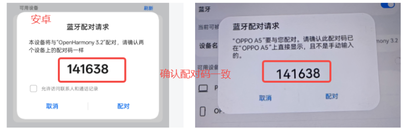
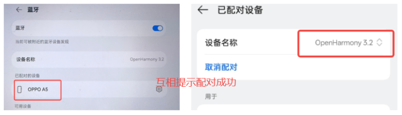
Pairing successful, Bluetooth test normal.

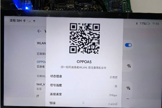
WiFi Connection Testing

Use the board to connect to the phone hotspot "OPPOA5" for testing. After successful connection, you can see the connection information in settings:

WiFi Connection Information

Let's open the browser to test if the network is normal:

Browser Test

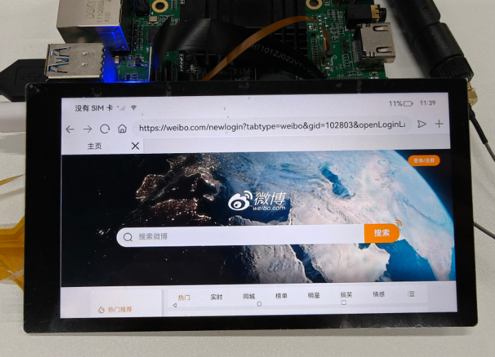
Successfully accessed Weibo, network connection is normal.

4 WIFI & BT Usage - Official Library Method

Data Path

hap package: /05-Development-Materials/01-OpenHarmony-Development-Materials/Peripheral-Test-APP/HAP/NET_TEST.hap

Source code: /05-Development-Materials/01-OpenHarmony-Development-Materials/Peripheral-Test-APP/SRC/NATEWORK_TEST

See: Ethernet Testing

Edit this page on GitHub
Last Updated:
Contributors: ZSL