
Display and Touch
The MB-E30P development board is designed based on the Rockchip RK3568J chip and provides rich display interfaces, supporting multiple display output methods. The development board is equipped with mainstream display interfaces such as HDMI and MIPI DSI, which can meet the display needs of different application scenarios.
1 Display Interface Overview
1.1 Supported Display Interfaces
| Interface Type | Quantity | Maximum Resolution | Features |
|---|---|---|---|
| HDMI | 1 | 4K@60Hz | Standard Type-A interface, supports hot-plug |
| MIPI DSI | 1 | 1920×1080 | Low power, suitable for embedded displays |
| eDP | 1 | 2560×1600@60Hz | High-performance embedded display interface |
1.2 Display Controller Features
- GPU: ARM G52 2EE, supports OpenGL ES 1.1/2.0/3.2, OpenCL 2.0, Vulkan 1.1
- 2D Acceleration: Embedded high-performance 2D acceleration hardware
- Multi-display Output: Supports simultaneous output to multiple display devices
- Color Support: Supports RGB 4:4:4 color format
- Hardware Acceleration: Supports hardware acceleration for video decoding and graphics rendering
2 MIPI DSI Interface
2.1 MIPI DSI Technology Introduction
MIPI DSI (Display Serial Interface) is a display interface standard developed by the MIPI Alliance specifically for mobile devices, with the following characteristics:
- Low-power design: Optimized for mobile and embedded devices
- High integration: Reduces PCB routing complexity
- Strong anti-interference ability: Differential signal transmission, resistant to EMI interference
- Flexible configuration: Supports 1-4 data lane configurations
2.2 Hardware Connection
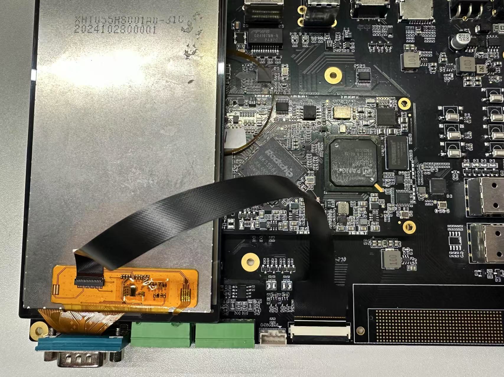 Connect the MIPI display to the development board's MIPI interface through the FPC ribbon cable as shown in the figure. Ensure the display's power and signal lines are connected correctly.
2.3 MIPI Screen Display Test
Power on the development board; you can see the following interface on the MIPI screen.

2.4 Backlight Test
Execute the following command to change the screen brightness by modifying the brightness level.
root@linaro-alip:/# echo 1 > /sys/class/backlight/backlight/brightness
root@linaro-alip:/# echo 255 > /sys/class/backlight/backlight/brightness
3 HDMI Interface
3.1 HDMI Technology Introduction
HDMI (High Definition Multimedia Interface) is a high-definition multimedia interface — a pure digital audio/video transmission interface that can transmit both audio and video data simultaneously over a single cable.
3.2 HDMI Interface Type
The development board uses a standard HDMI Type-A interface. The pin definitions are as follows:
| Pin | Signal Name | Function Description |
|---|---|---|
| 1 | TMDS Data2+ | TMDS data channel 2 positive signal |
| 2 | TMDS Data2 Shield | TMDS data channel 2 shield |
| 3 | TMDS Data2- | TMDS data channel 2 negative signal |
| 4 | TMDS Data1+ | TMDS data channel 1 positive signal |
| 5 | TMDS Data1 Shield | TMDS data channel 1 shield |
| 6 | TMDS Data1- | TMDS data channel 1 negative signal |
| 7 | TMDS Data0+ | TMDS data channel 0 positive signal |
| 8 | TMDS Data0 Shield | TMDS data channel 0 shield |
| 9 | TMDS Data0- | TMDS data channel 0 negative signal |
| 10 | TMDS Clock+ | TMDS clock positive signal |
| 11 | TMDS Clock Shield | TMDS clock shield |
| 12 | TMDS Clock- | TMDS clock negative signal |
| 13 | CEC | Consumer Electronics Control |
| 14 | Reserved | Reserved |
| 15 | SCL | I2C clock line |
| 16 | SDA | I2C data line |
| 17 | DDC/CEC Ground | DDC/CEC ground line |
| 18 | +5V Power | +5V power |
| 19 | Hot Plug Detect | Hot-plug detection |
The development board's HDMI interface is a standard HDMI and supports hot-plug with auto-adaptive resolution.
3.3 Switching Resolution on the Desktop
- Open System Settings and find Display
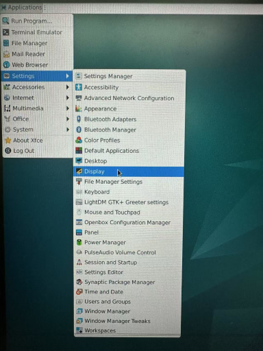
- Click Resolution to switch between different resolutions
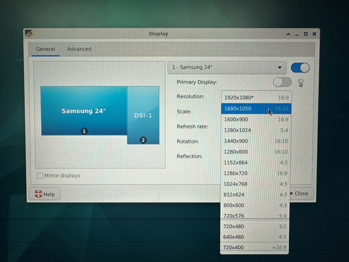
3.4 Switching Resolutions from the Command Line
- Use the
xrandr -qparameter to view the resolutions currently supported by your screen:
root@linaro-alip:/# xrandr -q
Screen 0: minimum 320 x 200, current 2640 x 1280, maximum 16384 x 16384
HDMI-1 connected 1920x1080+0+0 (normal left inverted right x axis y axis) 527mm x 296mm
   1920x1080     60.00*+  74.97    50.00    59.94
   1680x1050     59.88
   1600x900      60.00
   1280x1024     75.02    60.02
   1440x900      59.90
   1280x800      59.91
   1152x864      75.00
   1280x720      60.00    50.00    59.94
   1024x768      75.03    70.07    60.00
   832x624       74.55
   800x600       72.19    75.00    60.32    56.25
   720x576       50.00
   720x480       60.00    59.94
   640x480       75.00    72.81    66.67    60.00    59.94
   720x400       70.08
Use the
xrandr -s 0command to restore the screen to its original resolutionUse
xrandr -sto specify the screen resolution size
For example:
xrandr -s 1280x8004 eDP Interface
4.1 eDP Technology Introduction
eDP (Embedded DisplayPort) is a digital display interface standard designed specifically for internal connections, formulated by the Video Electronics Standards Association (VESA). eDP is an embedded-optimized version of the DisplayPort standard, primarily used for connections between the mainboard and built-in displays in devices such as laptops, tablets, and all-in-ones.
4.2 RK3568J eDP Controller Features
- eDP Version: Supports eDP 1.3 standard
- Maximum Resolution: 2560×1600@60Hz
- Data Lanes: Supports up to 4 physical lanes
- Color Depth: Supports up to 10bit color depth
- Link Rate: Supports 1.62Gbps, 2.7Gbps, 5.4Gbps
- Audio Support: Supports audio data transmission
- Adaptability: Supports link training and adaptive adjustment
4.3 eDP Interface Composition
The eDP interface mainly includes the following signals:
| Signal Name | Function Description |
|---|---|
| Main-Link | Main link, used to transmit video/audio data |
| TX0+/TX0- | Data lane 0 differential signal pair |
| TX1+/TX1- | Data lane 1 differential signal pair |
| TX2+/TX2- | Data lane 2 differential signal pair |
| TX3+/TX3- | Data lane 3 differential signal pair |
| AUX+/AUX- | Auxiliary channel, used to transmit configuration commands |
| HPD | Hot-plug detect signal |
5 Touchscreen
The development board has a group of I2C TP interfaces; the default touch IC driver is gt911.
Connect as shown in the figure below:

Swipe or tap the screen to test whether it works normally.