
03 - MPU6050 Gyroscope Application
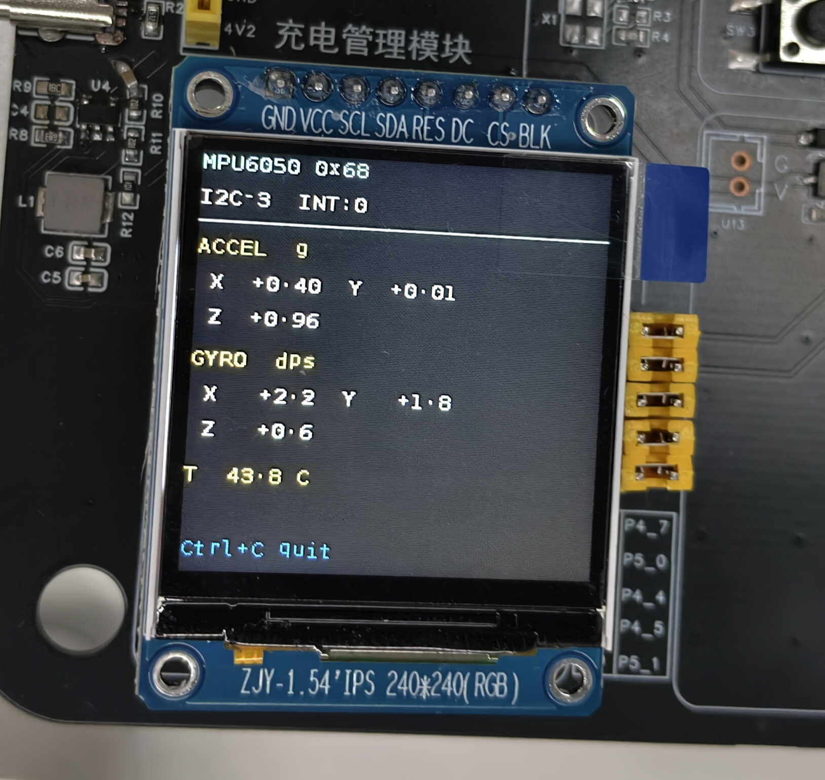
This chapter describes the MPU6050 six-axis motion sensor application example on the Pico-G1 expansion board — mpu6050_display. It demonstrates how to read acceleration, angular velocity, and temperature data from the MPU6050 sensor over the I2C interface and display them in real time on a TFT screen. It is a practical example for learning I2C sensor communication and motion data processing.
The application source code lives in the SDK directory source/app/03_mpu6050_display/, providing a complete implementation of I2C sensor reading and data processing.
1 Application Overview
1.1 Features
- I2C sensor communication: demonstrates reading MPU6050 sensor data over the I2C interface
- Six-axis data acquisition: reads three-axis acceleration and three-axis angular velocity simultaneously
- Temperature monitoring: reads the sensor's internal temperature data
- Real-time display: shows motion data on a TFT screen
- INT pin monitoring: supports MPU6050 data-ready interrupt detection
- Multi-chip compatibility: supports MPU6050/MPU6500/MPU9250 and similar chips
1.2 Technical Specifications
| Parameter | Value |
|---|---|
I2C interface | I2C3 (/dev/i2c-3) |
Slave address | 0x68 (AD0 grounded) |
Accelerometer range | ±2g (16384 LSB/g) |
Gyroscope range | ±250°/s (131 LSB/°/s) |
Temperature accuracy | ±1°C |
Refresh interval | 150ms (configurable) |
TFT display | ST7789 240×240 |
1.3 Test Case List
| index | Name | Test command | Expected result (success) | Possible causes of failure |
|---|---|---|---|---|
| 1 | Basic acquisition | ./mpu6050_display | Screen shows acceleration, angular velocity, and temperature data | I2C connection failure, damaged sensor |
| 2 | Static test | Keep the module still | Z-axis acceleration is about ±1g | Wrong sensor orientation |
| 3 | Tilt test | Tilt the module | Acceleration on the corresponding axis changes | Data parsing error |
| 4 | Temperature test | Touch the sensor | The temperature value rises | Sensor failure |
1.4 Directory Structure
source/app/03_mpu6050_display/
├── Makefile              # Build script
├── main.c                # Main program
├── mpu6050.c             # MPU6050 driver implementation
├── mpu6050.h             # MPU6050 driver header
├── i2c_hal.c             # I2C HAL layer implementation
├── i2c_hal.h             # I2C HAL layer header
├── gpio_hal.c            # GPIO HAL layer implementation
├── gpio_hal.h            # GPIO HAL layer header
├── spi_hal.c             # SPI HAL layer implementation
├── spi_hal.h             # SPI HAL layer header
├── st7789.c              # ST7789 driver implementation
├── st7789.h              # ST7789 driver header
├── font8x16.h            # 8×16 ASCII bitmap font
└── README.md             # Documentation
2 Hardware Connection
2.1 Pin Definition
| Signal | On-board GPIO | Controller / node | Description |
|---|---|---|---|
| SCL | GPIO4_1 | I2C3 → /dev/i2c-3 | Bus shared with the OLED (0x3C) |
| SDA | GPIO4_2 | I2C3 → /dev/i2c-3 | Bus shared with the OLED |
| INT | GPIO0_0 | /dev/gpiochip0 line0 | Data-ready indication (optional) |
| AD0 | Tied to GND | — | Slave address = 0x68 |
| Display | SPI2 | /dev/spidev2.0 | ST7789 240×240 |
2.2 Hardware Circuit
Standard MPU6050 wiring:
     Pico-G1                   MPU6050 Module
  ┌───────────┐              ┌──────────────┐
  │           │              │              │
  │ GPIO4_1 ──┼────── SCL ──┤ SCL          │
  │           │              │              │
  │ GPIO4_2 ──┼────── SDA ──┤ SDA          │
  │           │              │              │
  │ GPIO0_0 ──┼────── INT ──┤ INT (optional) │
  │           │              │              │
  │    3.3V ──┼─────────────┤ VCC          │
  │           │              │              │
  │     GND ──┼─────────────┤ GND          │
  │           │              │    AD0 ─── GND│
  └───────────┘              └──────────────┘
Address selection
- AD0 tied to GND: I2C address = 0x68 (default)
- AD0 tied to VCC: I2C address = 0x69
- On most modules AD0 is already grounded; no extra wiring is needed
2.3 Pin Multiplexing
Pin multiplexing that needs to be configured:
| pad | Physical address | Value | Description |
|---|---|---|---|
| I2C3_SCL (GPIO4_1) | 0x100C0010 | 0x1002 | func2 = I2C3_SCL |
| I2C3_SDA (GPIO4_2) | 0x100C0014 | 0x1002 | func2 = I2C3_SDA |
| INT (GPIO0_0) | 0x112C0000 | 0x1000 | func0 (GPIO) + input enable |
3 Build and Deployment
3.1 Prerequisites
Before building this application, make sure the following preparations are complete:
- SDK environment ready: set up the cross-compilation toolchain and SDK by following Development Environment Setup
- MPU6050 module connected: the MPU6050 is correctly wired to the I2C3 interface
3.2 Building the Application
# Set the toolchain path
export PATH=$PATH:<SDK>/tools/linux/toolchains/arm-gcc12.2.0-linux-uclibceabi/bin

# Enter the example directory
cd <SDK>/source/app/03_mpu6050_display

# Build
make

# Clean
make clean
3.3 Deploying to the Board
# Transfer to the development board with SCP
scp mpu6050_display root@<board-IP>:/usr/bin/

# Or download via TFTP
tftp -g -r mpu6050_display <board-IP>
3.4 Running the Application
# Add execute permission
chmod +x /usr/bin/mpu6050_display

# Run the MPU6050 display example
/usr/bin/mpu6050_display
3.5 Expected Output
Console output
/mnt # ./mpu6050_display
[mpu] pad 复用:I2C3(4_1/4_2)->func2,GPIO0_0->func0
[mpu] pad 0x100C0010 -> 0x00001002
[mpu] pad 0x100C0014 -> 0x00001002
[mpu] pad 0x112C0000 -> 0x00001000
[mpu] 初始化 SPI 屏(/dev/spidev2.0)...
[spi] pad 0x100C0028 -> 0x00001004
[spi] pad 0x100C002C -> 0x00001004
[spi] pad 0x100C0030 -> 0x00001000
[spi] pad 0x100C0020 -> 0x00001005
[spi] pad 0x100C001C -> 0x00001005
[spi] opening /dev/spidev2.0 ...
[spi] spidev opened, fd=3
[spi] spidev mode/bits/speed set (MODE3/8b/24MHz)
[spi] chardev request DC  @ /dev/gpiochip4 line 5 ...
[spi] chardev request RES @ /dev/gpiochip4 line 4 ...
[spi] chardev request CS  @ /dev/gpiochip5 line 1 ...
[spi] chardev-verify: DC=0(expect0) RES=1(expect1) CS=1(expect1)  ==> OK(chardev 真驱动了引脚)
[spi] spi_hal_init done
[tft] init: SLPOUT
[tft] init: SLPOUT +120ms ok
[tft] init: config cmds ok
[tft] init: DISPON
[tft] init: DISPON ok
[tft] init: clear-flush start
[tft] flush #1 start
[tft] flush #1 done
[tft] init: clear-flush done
[mpu] SPI 屏就绪。
[mpu] 初始化 MPU6050(/dev/i2c-3 addr 0x68)...
[mpu] WHO_AM_I = 0x70
[mpu] 识别为 MPU6500
[mpu] 初始化成功 @ /dev/i2c-3 addr 0x68 (±2g / ±250dps, 100Hz)
[mpu] 采集显示中,每 150ms 刷新,Ctrl+C 退出。
TFT screen display
4 Troubleshooting
| Problem | Possible cause | Solution |
|---|---|---|
| WHO_AM_I read failure | I2C connection failure, wrong address | Check wiring, confirm the address configuration |
| WHO_AM_I = 0xFF | No I2C response | Check SCL/SDA wiring, confirm the power supply |
| WHO_AM_I is not 0x68 | MPU6500/MPU9250 chip | The driver already supports 0x70/0x71 |
| Data not updating | Sensor not woken up | Check the PWR_MGMT_1 register |