
HOME
Shop
  • English
  • 简体中文
HOME
Shop
  • English
  • 简体中文
  • Product Series

    • FPGA+ARM

      • GM-3568JHF

        • Introduction

          • GM-3568JHF Introduction
        • Quick Start

          • Preface
          • Environment Setup
          • Compilation Notes
          • Flashing Guide
          • Debugging Tools
          • Software Update
          • Viewing System Information
          • Test Commands
          • Application Compilation
          • Source Code Access
        • Peripherals & Interfaces

          • USB
          • Display and Touch
          • Ethernet
          • WIFI
          • Bluetooth
          • TF-Card
          • Audio
          • Serial Port
          • CAN
          • RTC
        • Application Development

          • UART Read/Write Demo
          • Key Detection Demo
          • LED Blink Demo
          • MIPI Screen Detection Demo
          • Read USB Device Information Demo
          • FAN Detection Demo
          • FPGA FSPI Communication Demo
          • FPGA DMA Read/Write Demo
          • GPS Debugging Demo
          • Ethernet Test Demo
          • RS485 Read/Write Demo
          • FPGA I2C Read/Write Demo
          • PN532 NFC Card-Reading Demo
          • TF Card Read/Write Demo
        • QT Development

          • ARM64 Cross-Compiler Environment Setup
          • Adding a QT Program to Boot Auto-Start
        • RKNN_NPU Development

          • RK3568 NPU Overview
          • Development Environment Setup
          • Run the Official YOLOv5 Example
        • FPGA Development

          • ARM and FPGA Communication
          • FPGA Development Manual
        • Others

          • Modifying the Root Filesystem
          • System Auto-Start Services
        • Downloads

          • Downloads
      • MB-E30P

        • Introduction

          • MB-E30P Introduction
        • Quick Start

          • Preface
          • Environment Setup
          • Compilation Instructions
          • Flashing Guide
          • Debugging Tools
          • Software Update
          • Viewing Information
          • Test Commands
          • Application Compilation
          • Source Code Acquisition
        • Peripherals & Interfaces

          • USB
          • Display and Touch
          • Ethernet
          • WIFI
          • Bluetooth
          • TF-Card
          • Audio
          • RTC
        • Application Development

          • Key Detection Demo
          • LED Blink Demo
          • MIPI Screen Detection Demo
          • Read USB Device Information Demo
          • FAN Detection Demo
          • FPGA FSPI Communication Demo
          • FPGA DMA Read/Write Demo
          • Ethernet Test Demo
          • FPGA IIC Read/Write Demo
          • PN532 NFC Card Reading Demo
          • TF Card Read/Write Demo
        • QT Development

          • ARM64 Cross-Compiler Environment Setup
          • Adding a QT Program to the Boot Auto-Start Service
        • RKNN_NPU Development

          • RK3568 NPU Overview
          • Development Environment Setup
          • Run the Official YOLOv5 Example
          • Model Conversion In Detail
          • Run Custom Models on the Board
        • FPGA Development

          • ARM and FPGA Communication
          • FPGA Development Manual
        • Others

          • Modifying the Root Filesystem
          • System Auto-Start Service
        • Downloads

          • Downloads
    • ShimetaPi

      • M4-R1

        • Introduction

          • M4-R1 Introduction
        • Quick Start

          • OpenHarmony Overview
          • Image Burning
          • Application Development Quick Start
          • Device Development Quick Start
        • Application Development

          • ArkUI

            • ArkTS Language Overview
            • UI Components - Row Container Introduction
            • UI Components - Column Container Introduction
            • UI Components - Text Component
            • UI Components - Toggle Component
            • UI Components - Slider Component
            • UI Components - Animation Component & Transition Component
          • Documentation

            • OpenHarmony Official Materials
          • Development Notes

            • Full-SDK Replacement Tutorial
            • Introducing and Using Third-Party Libraries
            • HDC Debugging
            • Restore Factory Mode via Command Line
            • Upgrade App to System Permission
          • First App

            • Build Your First ArkTS Application - HelloWorld
          • Demos

            • Serial-Debug-Assistant Application Demo
            • Writing-Board Application Demo
            • Digital Clock Application Demo
            • Wi-Fi Information Acquisition Application Demo
        • Device Development

          • Ubuntu Development

            • Environment Setup
            • Download Source Code
            • Compile Source Code
          • DevEco Device Tool

            • Tool Introduction
            • Development Environment Construction
            • Import the SDK
            • HUAWEI DevEco Tool Function Introduction
        • Kernel Peripherals & Interfaces

          • Guide
          • Device Tree Introduction
          • NAPI Introduction
          • ArkTS Introduction
          • NAPI Development Hands-on Demo
          • GPIO Introduction
          • I2C Communication
          • SPI Communication
          • PWM Control
          • UART Communication
          • TF Card (MicroSD)
          • Screen (Display)
          • Touch
          • Ethernet
          • M.2 SSD
          • Audio
          • WIFI & BT
          • Camera
        • Downloads

          • Downloads
      • M5-R1

        • Introduction

          • M5-R1 Development Docs
        • Quick Start

          • Image Burning
          • Environment Setup
          • Download Source Code
        • Peripherals & Interfaces

          • Raspberry Pi Interfaces
          • GPIO Interface
          • I2C Interface
          • SPI Communication
          • PWM Control
          • Serial Port Communication
          • TF Card
          • Display
          • Touch
          • Audio
          • RTC
          • Ethernet
          • M.2
          • MINI-PCIE
          • Camera
          • WIFI & BT
        • Downloads

          • Downloads
      • Pico-G1

        • Product Overview

          • Product Introduction
          • SDK Version Information
        • Quick Start

          • Development Environment Setup
          • Image Build
          • Image Flashing
          • System Login
          • Network Configuration
          • File Transfer
          • SDK Directory Structure
          • Deploying Your First Application
          • Deploying Your First Driver
          • Mounting an SD Card
        • Peripherals & Interfaces

          • GPIO Control
          • UART Serial Communication
          • I2C Communication
          • SPI Communication
        • MPP Media Development

          • MPP Media Processing Software
          • Image Processing Chain
          • Video Input
          • Image Encoding
        • NPU & AI

          • NPU Driver and Runtime Library Architecture
          • .xmm Model Loading
          • SVP Video Processing
          • AI Noise Reduction (AI_NR)
        • Application Samples

          • Encryption/Decryption Application
          • ADC Acquisition Application
          • Low-Power Application
          • Audio Processing Application
          • Video Encoding Application
          • Video Input Application
          • Video Graphics Subsystem (VGS) Application
          • 08 Region Overlay Application
          • 09 Intelligent Video Engine Application
          • 10 UVC Webcam Application
          • 11 All-in-One Quickstart Application
          • 12 FPN Correction Application
          • 13 Regional Motion Detection Application
          • 14 MTCNN Face Detection Application
        • Expansion Board Peripheral Examples

          • 00 - Pico Expansion Board Peripheral Examples Overview
          • 01 - OLED Display Application
          • 02 - TFT Display Application
          • 03 - MPU6050 Gyroscope Application
          • 04 - ADC Acquisition Application
          • 05 - Passive Buzzer Application
          • 06 - MQ Gas Sensor Application
          • 07 - GPS Positioning Application
          • 08 - SHT20 Temperature & Humidity Application
          • 09 - Ultrasonic Ranging Application
          • 10 - SpO2 Sensor Application
          • 11 - DC Motor Control Application
          • 12 - Servo Control Application
    • OpenHarmony

      • SC-3568HA

        • Introduction

          • SC-3568HA Overview
        • Quick Start Guide

          • OpenHarmony Overview
          • Image Flashing
          • Setting Up the Development Environment
          • Hello World Application and Deployment
        • Application Development

          • ArkUI

            • Introduction to ArkTS Language
            • Introduction to UI Components and Practical Applications (Part 1)
            • Introduction to UI Components and Practical Applications (Part 2)
            • Introduction to UI Components and Practical Applications (Part 3)
          • Expand

            • Getting Started Guide
            • Referencing and Using Third-Party Libraries
            • Application Compilation and Deployment
            • Command-Line Factory Reset
            • System Debugging -- HDC Debugging
            • APP Stability Testing
            • Chapter 7 Application Testing
        • Device Development

          • Environment Setup
          • Download Source Code
          • Compiling Source Code
        • Peripheral And Interface

          • Raspberry Pi interface
          • GPIO Interface
          • I2C Interface
          • SPI communication
          • PWM (Pulse Width Modulation) control
          • Serial port communication
          • TF Card
          • Display Screen
          • Touch
          • Audio
          • RTC
          • Ethernet
          • M.2
          • MINI-PCIE
          • Camera
          • WIFI&BT
          • Raspberry Pi expansion board
        • Downloads

          • Downloads
      • M-K1HSE

        • Introduction

          • M-K1HSE Introduction
        • Quick Start

          • Development environment construction
          • Source code acquisition
          • Compilation Notes
          • Burning Guide
        • Application Development

          • Application Development Environment Setup
          • First Application - Hello World
        • Peripherals and interfaces

          • 01 Audio
          • 02 RS485
          • 03 Display
        • System customization development

          • System transplant
          • System customization
          • Driver Development
          • System Debugging
          • OTA Update
        • Downloads

          • Downloads
    • HVS Camera

      • Quick Start

        • SDK Overview
        • Downloads
        • Your First C++ Program
        • Python Data Analysis
        • MultiVision Studio
      • Development

        • Programming Guides

          • Open Camera
          • Read Events
          • Recording & Replay
          • Event Processing (Denoising)
          • Display & Visualization
          • Tuning
          • Capture APS Image
        • Toolkit SDK

          • Hybrid Vision Toolkit
          • Quick Start
          • C++ API
          • Python API
        • Algorithm

          • Hybrid Vision Algo
          • Hybrid Vision Algo API
          • Windows Algo SDK
        • Samples Overview
        • Applications
      • Fundamentals

        • Event Camera Fundamentals
        • HVS Hybrid Vision
        • Event Visualization
        • Data Formats Reference
        • Glossary
        • Bias & Tuning
        • Video Tutorials
      • USB Cameras

        • HVS Camera Quick Start
        • Networking Capabilities

          • HVS Camera System Architecture
          • EVS Network Server
          • EVS Time Sync
          • Web Window
        • HVS Camera Compatibility Matrix
        • FAQ & Troubleshooting Guide
        • Products

          • CF-NRS1 (Lingguang No.1 Hybrid Vision Camera)
      • MIPI Modules

        • MIPI Module Quick Start
        • Carrier Boards

          • RDK X5 Carrier Board Adaptation
          • Raspberry Pi Carrier Board Adaptation
          • Digua Pi Carrier Board Adaptation
          • ShimeTai Board Carrier Board Adaptation
        • MIPI Module Compatibility Matrix
        • Products

          • EVS_003 Sensor Module
    • AI-model

      • 1684XB-32T

        • Introduction

          • AIBOX-1684XB-32 Introduction
        • Quick Start

          • First Use
          • Network Configuration
          • Disk Usage
          • Memory Allocation
          • Fan Control Strategy
          • Firmware Upgrade
          • Cross Compilation
          • Model Quantization
        • Application Development

          • Development Overview

            • Sophgo SDK Development
            • Sophgo Demo Introduction
          • Large Language Models

            • Deploying Llama3 Example
            • Sophon LLM_api_server Development
            • Deploying MiniCPM-V-2_6
            • Qwen-2-5-VL Image and Video Recognition Demo
            • Qwen3-chat Demo
            • Qwen3-Qwen Agent-MCP Development
            • Qwen3-langchain-AI Agent
          • Deep Learning

            • ResNet (Image Classification)
            • LPRNet (License Plate Recognition)
            • SAM (General Image Segmentation Foundation Model)
            • YOLOv5 (Object Detection)
            • OpenPose (Human Keypoint Detection)
            • PP-OCR (Optical Character Recognition)
        • Downloads

          • Downloads
      • 1684X-416T

        • Introduction

          • AIBOX-1684X-416 Introduction
        • Demo Quick Guide

          • ShimeTai Intelligent Monitoring Demo Quick Usage Guide
      • RDK-X5

        • Introduction

          • RDK-X5 Hardware Introduction
        • Quick Start

          • RDK-X5 Quick Start
        • Application Development

          • AI Online Model Development

            • Experiment 01 - Access Volcengine Doubao AI
            • Experiment 02 - Image Analysis
            • Experiment 03 - Multimodal Visual Analysis & Localization
            • Experiment 04 - Multimodal Image-Text Comparison
            • Experiment 05 - Multimodal Document/Table Analysis
            • Experiment 06 - Camera-based AI Visual Analysis
          • Large Language Models

            • Experiment 01 - Speech Recognition
            • Experiment 02 - Voice Conversation
            • Experiment 03 - Multimodal Image Analysis - Voice
            • Experiment 04 - Multimodal Image Comparison - Voice
            • Experiment 05 - Multimodal Document Analysis - Voice
            • Experiment 06 - Multimodal Vision Application - Voice
          • ROS2 Basics

            • Experiment 01 - Environment Setup
            • Experiment 02 - Create & Build a Workspace Package
            • Experiment 03 - Run ROS2 Topic Communication Node
            • Experiment 04 - ROS2 Camera Application
          • 40-pin IO Development

            • Experiment 01 - GPIO Output (LED Blink)
            • Experiment 02 - GPIO Input
            • Experiment 03 - Button-controlled LED
            • Experiment 04 - PWM Output
            • Experiment 05 - Serial Output
            • Experiment 06 - I2C Experiment
            • Experiment 07 - SPI Experiment
          • USB Module Usage

            • Experiment 01 - USB Voice Module Usage
            • Experiment 02 - Sound Source Localization Module
          • Machine Vision Practice

            • Experiment 01 - Open USB Camera
            • Experiment 02 - Color Recognition
            • Experiment 03 - Gesture Recognition
            • Experiment 04 - YOLOv5 Object Detection
      • RDK-S100

        • Introduction

          • RDK-S100 Hardware Introduction
        • Quick Start

          • RDK-S100 Quick Start
        • Application Development

          • AI Online Model Development

            • Experiment 01 - Access Volcengine Doubao AI
            • Experiment 02 - Image Analysis
            • Experiment 03 - Multimodal Visual Analysis & Localization
            • Experiment 04 - Multimodal Image-Text Comparison
            • Experiment 05 - Multimodal Document/Table Analysis
            • Experiment 06 - Camera-based AI Visual Analysis
          • Large Language Models

            • Experiment 01 - Speech Recognition
            • Experiment 02 - Voice Conversation
            • Experiment 03 - Multimodal Image Analysis - Voice
            • Experiment 04 - Multimodal Image Comparison - Voice
            • Experiment 05 - Multimodal Document Analysis - Voice
            • Experiment 06 - Multimodal Vision Application - Voice
          • ROS2 Basics

            • Experiment 01 - Environment Setup
            • Experiment 02 - Create & Build a Workspace Package
            • Experiment 03 - Run ROS2 Topic Communication Node
            • Experiment 04 - ROS2 Camera Application
          • 40-pin IO Development

            • Experiment 01 - GPIO Output (LED Blink)
            • Experiment 02 - GPIO Input
            • Experiment 03 - Button-controlled LED
            • Experiment 04 - PWM Output
            • Experiment 05 - Serial Output
            • Experiment 06 - I2C Experiment
            • Experiment 07 - SPI Experiment
          • USB Module Usage

            • Experiment 01 - USB Voice Module Usage
            • Experiment 02 - Sound Source Localization Module
          • Machine Vision Practice

            • Experiment 01 - Open USB Camera
            • Experiment 02 - Image Processing Basics
            • Experiment 03 - Object Detection
            • Experiment 04 - Image Segmentation
      • RK1828

        • Introduction

          • M5-182X-A1 AI Edge Box - Product Introduction
          • M5-182X-A1 Hardware Specifications
          • M5-182X-A1 Usage & Safety
        • Quick Start

          • M5-182X-A1 Image Flashing
          • RK182X Hardware Installation & Verification
          • RK182X Development Environment Quick Setup
          • RK182X SDK Overview
          • RK182X Environment Setup in Detail
          • RK182X Quick Start
          • Vendor SDK Data Extraction Record
        • Development Guide

          • ClawChips Architecture and Principles
          • SKILL User Manual
          • RK182X Series LLM Inference (RK1828 Model)
          • RK182X Series CNN Inference (RK1828 Model)
          • Model Conversion
          • RK182X AI Agent Application Development Guide
          • RK182X Industrial Anomaly Detection Application
        • SDK Reference

          • RKNN3-SDK Overview

            • RKNN3 SDK Overview
          • RKNN3-Toolkit

            • RKNN3 Toolkit Installation and Usage
          • RKLLM

            • RKLLM On-Device LLM Inference
          • RK182X Series NPU Overview and Architecture (RK1828 Model)
          • RK182X INT8 Quantized Inference Deployment
          • RK182X MPP Multimedia Framework
          • MPP Details

            • RK182X Video Decoding
            • RK182X Video Encoding
          • NPU Details

            • RKNN Model Conversion
            • RK182X NPU INT8 Quantized Inference
            • RK182X Multi-Model Parallel Inference
          • RGA Details

            • RK182X RGA 2D Graphics Acceleration
          • VPU Details

            • RK182X VPU Codec
        • Hardware Reference

          • RK182X Series Hardware Architecture Overview (RK1828 Model)
          • RK182X Pin Definitions and Multiplexing Configuration
          • RK182X Pin Definitions
          • RK182X Power Management
          • RK182X Clock and PLL Configuration
          • RK182X Clock and Frequency Configuration
        • Tutorials

          • Hello World
          • Hello RK1828 - The First Program
          • RTSP Streaming
          • RTSP Streaming + AI Analysis
          • ShiMetaPi AI Lobster One-Click Deployment
          • PaddleOCR-VL Text Recognition
          • Qwen3-1.7B LLM Text Chat
          • AI Multi-View Inspection (Qwen3-VL Wrapper)
          • YOLOv5 Object Detection
        • Downloads

          • Downloads
        • FAQ

          • FAQ
    • Core-Board

      • C-3568BQ

        • Introduction

          • C-3568BQ Overview
      • C-3588LQ

        • Introduction

          • C-3588LQ Overview
      • GC-3568JBAF

        • Introduction

          • GC-3568JBAF Overview
      • C-K1BA

        • Introduction

          • C-K1BA Overview
    • Software Platform

      • ShiMetaPi Workbench

        • Introduction

          • Product Overview
          • Core Architecture
          • Feature Entries
          • Supported Hardware
          • Release Notes
        • Quick Start

          • Install & Login
          • Connect the Device
          • Set Up the Environment
          • Connect to AIHub
          • First Inference
        • User Guide

          • Workspace Overview
          • Device Manager
          • Model Market
          • One-Click Deploy
          • Vision — SVP
          • Vision - Custom Models
          • shimeta-py IDE
          • Terminal
          • Agent Debug Assistant
          • Settings and Resources
        • FAQ

          • Installation & Login
          • Device Connection
          • Models & Deployment
          • Vision & Runtime
          • Settings & Other
      • ShimetaPi Repository

        • Introduction

          • ShimetaPi Software Repository
        • Pico G1 (GK7206)

          • Quick Start

            • Installation & First Inference
            • shimeta_infer — Image Inference
            • shimeta_camera — Real-time Camera Inference
            • SVP Scene Detection
            • File Transfer & Built-in Model Reference
            • FAQ
          • HTTP API & Python SDK

            • HTTP API Reference
      • Model Fine-tuning Platform

        • Introduction

          • Model Training Platform
        • Quick Start

          • Register & Login
          • Create Your First Model (30-Minute Quick Experience)
        • Training Guide

          • Data Preparation & Annotation
          • Training Parameter Configuration
          • Start & Monitor Training
          • Model Evaluation & Testing
        • Model Deployment

          • Export Model
          • Deploy to Edge Device

Event Camera Fundamentals

Our cameras are based on the AlpsenTek HVS (Hybrid Vision) chip: the same pixel array simultaneously outputs an APS image stream and an EVS event stream. For the fusion architecture see HVS Hybrid Vision; for terminology see Glossary; for data formats see Data Formats.

1. What is event data?

Basic principle

Scene changes are recorded as an asynchronous event stream. Unlike a conventional frame-based image sensor, every pixel works independently and fires an event only when it detects a brightness change (e.g. object motion, a sudden light change).

This mechanism resembles how neurons in the human retina work: only dynamic information is transmitted, static background is ignored.
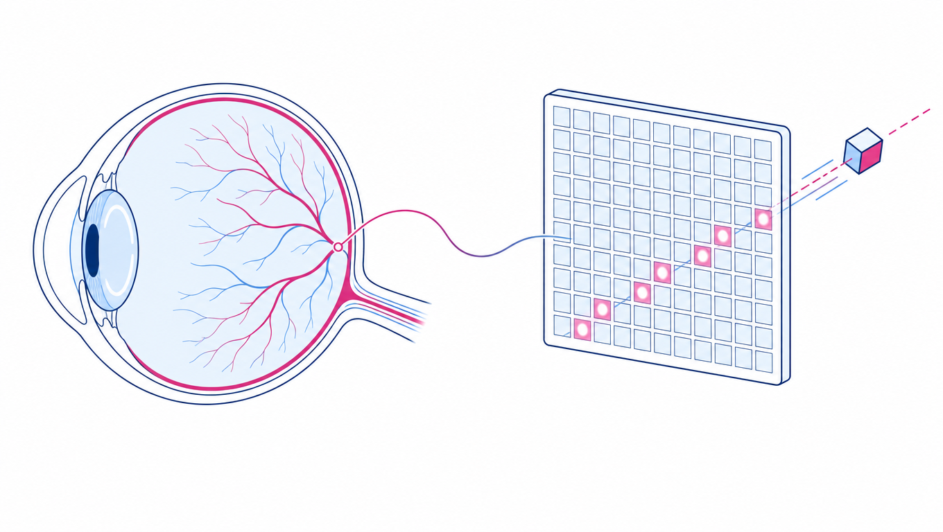
Event-camera principle illustration

Event-camera retina-like mechanism illustration

An event camera is composed of thousands of independently operating pixel units. Each pixel, with microsecond-level response speed, independently monitors brightness changes within its field of view. As soon as a brightness change exceeds a set threshold, that pixel immediately generates an "event".

Each event contains:

  • x, y: pixel position
  • t: timestamp (usually microsecond-level)
  • p: polarity (indicates whether brightness increased or decreased)

Event = (x, y, t, polarity)

Unlike the synchronous readout of frame images, events are generated asynchronously, sparsely, and continuously. This data format moves us from the "take a photo" paradigm into a new era of "perceiving change".

For example, when a golfer swings, the sensor captures only the trajectory of the ball and club, not the stationary sky or grass.

Pixel-level working principle

To understand where the above properties come from, look inside a single pixel:

  • Independent pixel operation: each pixel has its own circuit and monitors only the brightness at its own location, without depending on other pixels and without waiting for a global exposure — this is the physical source of "asynchrony".
  • Logarithmic brightness response: the pixel measures the logarithmic change of brightness (not linear brightness). The same proportional brightness change (e.g. doubling or halving) produces the same response magnitude regardless of whether the background is bright or dim — this is the root of the event camera's high dynamic range.
  • Threshold-crossing trigger: when the logarithmic brightness change accumulates past a set threshold, the pixel fires an event immediately, without waiting for other pixels or an "exposure period" — this is the source of microsecond-level response and zero motion blur.
  • Polarity (ON/OFF): brightening past the threshold → ON event (p=1); darkening past the threshold → OFF event (p=0). Pixels that stay unchanged emit no events — this is the source of sparsity, low power, and low bandwidth.
  • EPS (Events Per Second, event rate): the number of events generated per unit time, measuring how dynamically busy the scene is. Intense motion or jitter yields high EPS; a static scene has near-zero EPS.

One-line essential difference: a frame camera = "timed full-frame sampling" (fixed frame rate, all pixels synchronous); an event camera = "per-pixel asynchronous change-driven". Microsecond time resolution, low latency, sparsity, low power, high dynamic range — all stem from this fundamental difference.

Technical characteristics

  • Asynchrony and real-time performance: event data is output as a continuous stream with sub-millisecond response, avoiding the motion blur of conventional frame sensors. Each pixel triggers independently, so data generation is not bound by a fixed frame rate — suited to high-speed scenes (e.g. fast moving object tracking).
  • Data sparsity and low power: because only dynamic information is recorded, the event data volume is 1/10 to 1/1000 that of a conventional image sensor, significantly reducing compute demand and power consumption.
  • Strong environmental adaptability: the event sensor works stably under extreme lighting (low light or bright light), automatically adapting to brightness changes through independent pixel triggering, avoiding the under-/over-exposure problems of conventional sensors.
  • High temporal resolution: the event camera has microsecond-level time precision and can capture the tiniest brightness changes during high-speed motion. No matter how fast the target, the event never "blurs". A conventional frame camera captures images at 30 FPS; an event camera responds to change at millions of events per second.
  • Ultra-low latency: events are generated instantly, with no need to wait for a full frame to be captured. This makes event vision highly advantageous for real-time control, obstacle avoidance, gesture recognition, and similar tasks.
  • Very high dynamic range: because each pixel handles changes individually, event vision can operate at a dynamic range of 100 dB or higher. It stays clear even in environments where strong light and deep shadow coexist.
  • Data sparsity: only the changing parts trigger events, so the data volume drops sharply. A higher compression ratio means lower bandwidth and storage needs.

2. Event data vs. conventional frame images

PropertyConventional frame cameraEvent camera
Acquisition modeSynchronous framesAsynchronous events
Temporal resolutionMillisecond (30~120 FPS)Microsecond
Data densityDense (all pixels)Sparse (only changes)
LatencyHighLow
Dynamic rangeUsually < 60dBUp to 100dB+
PowerHighLower (output on demand)
Motion blurNoticeableAlmost none

The two are compared intuitively below — the frame camera records the whole picture (including static background), the event camera records only the moving target:
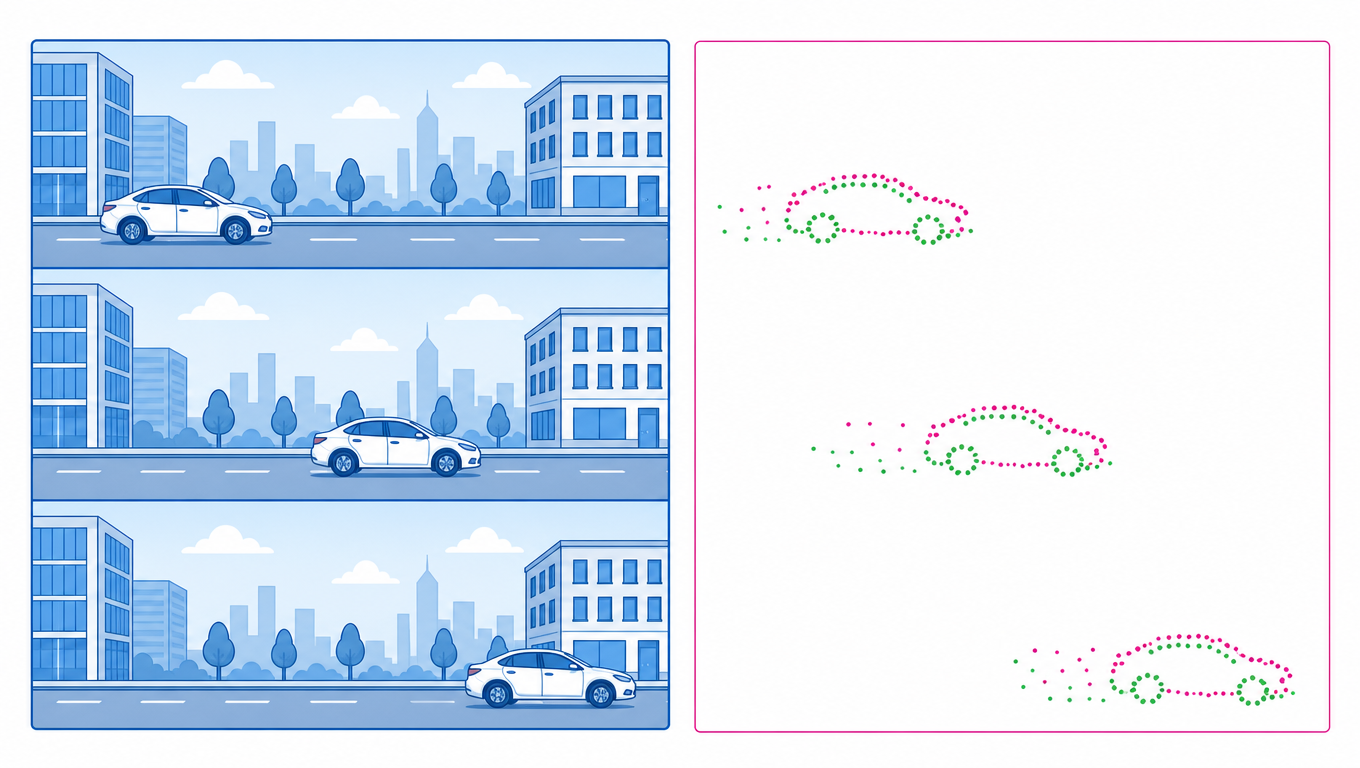
Frame image vs event image comparison

Taking a golf swing as an example, the event camera captures only the trajectory of the club and ball, not the stationary sky and grass:
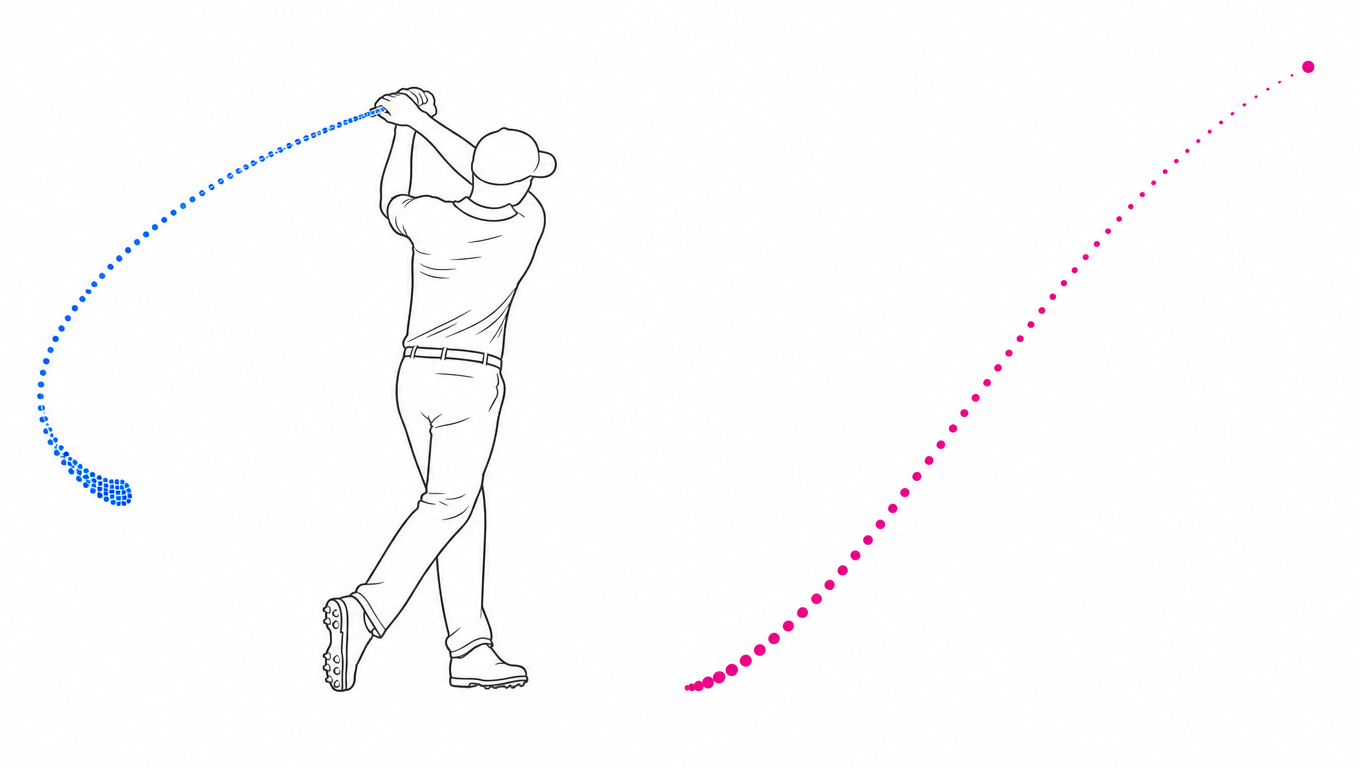
Golf swing: only the motion trajectory is recorded

3. HVS: pixel-level fusion of image + event

The above describes a "pure event camera". What our camera does is HVS (Hybrid Vision Sensor) — based on the AlpsenTek HVS chip, every pixel in the same pixel array has both an image-sampling chain and an event-detection chain. The camera therefore outputs both conventional APS image frames and an EVS event stream, and the two streams are synchronized at pixel level and microsecond level. Full introduction at HVS Hybrid Vision.

Three operating modes

ModeOutputSuited for
Image mode (APS)Full image frames (RAW)Static scenes, when texture/detail is needed
Event mode (EVS)Async event stream (x, y, p, t)High-speed motion, low latency, low power
Fusion mode (HVS)Image + event dual-stream syncWhen both detail and fast response are needed

Pixel-level fusion vs sensor-level fusion

There are two ways to put APS and EVS together, with very different outcomes:

  • Sensor-level fusion: two independent sensors (one APS + one EVS) placed physically side by side and aligned afterwards — there is parallax, the timing is not synchronized, and the package is bulky.
  • Pixel-level fusion (HVS / our approach): photoelectric conversion + image readout + event detection are integrated inside the same pixel, realized on-chip with architectures such as iampCOMB / GESP / IN-PULSE DiADC combined with PixMUX time-division multiplexing and BSI stacking — zero parallax, microsecond-level sync, single chip.

Dual-stream synergy: see clearly + see fast

APS and EVS each have their strengths and complement each other once fused:

  • APS: texture, color, static detail — "see clearly".
  • EVS: high-speed change, low latency, low bandwidth, >120dB high dynamic range — "see fast".

HVS vs pure EVS

Pure EVS sensors (e.g. the pure-event approach of Sony, Prophesee) pursue the ultimate event performance but usually do not output images; HVS delivers both image and event from a single chip, which is better suited to real-world scenarios that need "both a picture and events" — recognition, surveillance, interaction, and other applications that require image context.

4. How parameters affect the picture: accumulation time

The event camera itself only outputs sparse event points. To "see it as a picture", you need to accumulate the events within a time window into one frame; that window is the accumulation time:

  • Accumulation time too short → too few events, the picture is sparse and broken, the target is unclear;
  • Accumulation time appropriate → the outline of the moving target is clear;
  • Accumulation time too long → multiple motions overlap, the picture smears and blurs together.

How to adjust

For USB cameras, adjust the accumulation parameter in MultiVision Studio; for MIPI modules, handle frame stacking in evs_live_player on RDK X5.

The accumulation time is also coupled with the display frame rate: when the accumulation time equals the frame period (1 / frame rate), each event appears exactly once (full accumulation); when it is larger than the frame period, the same event spans multiple frames (over accumulation, appearing as slow motion / smear); when smaller than the frame period, most events are discarded (under accumulation). The trade-offs of the three schemes and XYT 3D visualization are covered in Event Visualization.

Recording ≠ visualization

The accumulation time is only a display parameter, similar to slow motion on a player. RAW / EVT2 files recorded with MultiVision Studio or evs_live_player store all the original events, independent of the accumulation time set during recording — it can be freely reset on playback. See Event Visualization.

Easy to confuse: temporal resolution ≠ latency

Temporal resolution refers to the precision of the event timestamp (microsecond-level), determined by the pixel circuit — "how finely it is recorded". Latency refers to the actual lag from when an event is generated to when it is consumed downstream, affected by transmission, processing, scheduling, etc. The two are independent: you can have microsecond temporal resolution but millisecond end-to-end latency.

5. Application scenarios

  • Industrial inspection: high-speed production-line defect detection
  • Smart transportation: fast target tracking, lane keeping
  • Robot navigation: stable navigation in low-light, complex dynamic scenes
  • Augmented/Virtual Reality (AR/VR): low-latency gesture recognition and interaction
  • Medical imaging: e.g. eye tracking, neural monitoring

6. Summary

Through biomimetic mechanisms and asynchronous processing, event data solves the compute bottleneck and dynamic-scene limitations of conventional vision systems. Its low power, high real-time performance, and privacy-friendly nature give it unique advantages in consumer electronics, autonomous driving, and more. As the neuromorphic computing ecosystem matures, event data will drive further advances in edge-intelligent devices.

In a conventional image-sensing system, the camera periodically captures a complete image at a fixed frame rate. Whether or not the scene changes, every frame contains the brightness values of the entire field of view. This approach is intuitive but has two fundamental limitations:

  • Low temporal resolution: a fixed frame rate cannot reflect rapidly changing dynamic scenes.
  • Redundant information: most pixels do not change significantly between adjacent frames yet are still captured repeatedly, wasting resources.

Event-based vision breaks this framework completely. It no longer "takes" pictures — it perceives change.

Edit this page on GitHub
Next
HVS Hybrid Vision