
HOME
Shop
  • English
  • 简体中文
HOME
Shop
  • English
  • 简体中文
  • Product Series

    • FPGA+ARM

      • GM-3568JHF

        • Introduction

          • GM-3568JHF Introduction
        • Quick Start

          • Preface
          • Environment Setup
          • Compilation Notes
          • Flashing Guide
          • Debugging Tools
          • Software Update
          • Viewing System Information
          • Test Commands
          • Application Compilation
          • Source Code Access
        • Peripherals & Interfaces

          • USB
          • Display and Touch
          • Ethernet
          • WIFI
          • Bluetooth
          • TF-Card
          • Audio
          • Serial Port
          • CAN
          • RTC
        • Application Development

          • UART Read/Write Demo
          • Key Detection Demo
          • LED Blink Demo
          • MIPI Screen Detection Demo
          • Read USB Device Information Demo
          • FAN Detection Demo
          • FPGA FSPI Communication Demo
          • FPGA DMA Read/Write Demo
          • GPS Debugging Demo
          • Ethernet Test Demo
          • RS485 Read/Write Demo
          • FPGA I2C Read/Write Demo
          • PN532 NFC Card-Reading Demo
          • TF Card Read/Write Demo
        • QT Development

          • ARM64 Cross-Compiler Environment Setup
          • Adding a QT Program to Boot Auto-Start
        • RKNN_NPU Development

          • RK3568 NPU Overview
          • Development Environment Setup
          • Run the Official YOLOv5 Example
        • FPGA Development

          • ARM and FPGA Communication
          • FPGA Development Manual
        • Others

          • Modifying the Root Filesystem
          • System Auto-Start Services
        • Downloads

          • Downloads
      • MB-E30P

        • Introduction

          • MB-E30P Introduction
        • Quick Start

          • Preface
          • Environment Setup
          • Compilation Instructions
          • Flashing Guide
          • Debugging Tools
          • Software Update
          • Viewing Information
          • Test Commands
          • Application Compilation
          • Source Code Acquisition
        • Peripherals & Interfaces

          • USB
          • Display and Touch
          • Ethernet
          • WIFI
          • Bluetooth
          • TF-Card
          • Audio
          • RTC
        • Application Development

          • Key Detection Demo
          • LED Blink Demo
          • MIPI Screen Detection Demo
          • Read USB Device Information Demo
          • FAN Detection Demo
          • FPGA FSPI Communication Demo
          • FPGA DMA Read/Write Demo
          • Ethernet Test Demo
          • FPGA IIC Read/Write Demo
          • PN532 NFC Card Reading Demo
          • TF Card Read/Write Demo
        • QT Development

          • ARM64 Cross-Compiler Environment Setup
          • Adding a QT Program to the Boot Auto-Start Service
        • RKNN_NPU Development

          • RK3568 NPU Overview
          • Development Environment Setup
          • Run the Official YOLOv5 Example
          • Model Conversion In Detail
          • Run Custom Models on the Board
        • FPGA Development

          • ARM and FPGA Communication
          • FPGA Development Manual
        • Others

          • Modifying the Root Filesystem
          • System Auto-Start Service
        • Downloads

          • Downloads
    • ShimetaPi

      • M4-R1

        • Introduction

          • M4-R1 Introduction
        • Quick Start

          • OpenHarmony Overview
          • Image Burning
          • Application Development Quick Start
          • Device Development Quick Start
        • Application Development

          • ArkUI

            • ArkTS Language Overview
            • UI Components - Row Container Introduction
            • UI Components - Column Container Introduction
            • UI Components - Text Component
            • UI Components - Toggle Component
            • UI Components - Slider Component
            • UI Components - Animation Component & Transition Component
          • Documentation

            • OpenHarmony Official Materials
          • Development Notes

            • Full-SDK Replacement Tutorial
            • Introducing and Using Third-Party Libraries
            • HDC Debugging
            • Restore Factory Mode via Command Line
            • Upgrade App to System Permission
          • First App

            • Build Your First ArkTS Application - HelloWorld
          • Demos

            • Serial-Debug-Assistant Application Demo
            • Writing-Board Application Demo
            • Digital Clock Application Demo
            • Wi-Fi Information Acquisition Application Demo
        • Device Development

          • Ubuntu Development

            • Environment Setup
            • Download Source Code
            • Compile Source Code
          • DevEco Device Tool

            • Tool Introduction
            • Development Environment Construction
            • Import the SDK
            • HUAWEI DevEco Tool Function Introduction
        • Kernel Peripherals & Interfaces

          • Guide
          • Device Tree Introduction
          • NAPI Introduction
          • ArkTS Introduction
          • NAPI Development Hands-on Demo
          • GPIO Introduction
          • I2C Communication
          • SPI Communication
          • PWM Control
          • UART Communication
          • TF Card (MicroSD)
          • Screen (Display)
          • Touch
          • Ethernet
          • M.2 SSD
          • Audio
          • WIFI & BT
          • Camera
        • Downloads

          • Downloads
      • M5-R1

        • Introduction

          • M5-R1 Development Docs
        • Quick Start

          • Image Burning
          • Environment Setup
          • Download Source Code
        • Peripherals & Interfaces

          • Raspberry Pi Interfaces
          • GPIO Interface
          • I2C Interface
          • SPI Communication
          • PWM Control
          • Serial Port Communication
          • TF Card
          • Display
          • Touch
          • Audio
          • RTC
          • Ethernet
          • M.2
          • MINI-PCIE
          • Camera
          • WIFI & BT
        • Downloads

          • Downloads
      • Pico-G1

        • Product Overview

          • Product Introduction
          • SDK Version Information
        • Quick Start

          • Development Environment Setup
          • Image Build
          • Image Flashing
          • System Login
          • Network Configuration
          • File Transfer
          • SDK Directory Structure
          • Deploying Your First Application
          • Deploying Your First Driver
          • Mounting an SD Card
        • Peripherals & Interfaces

          • GPIO Control
          • UART Serial Communication
          • I2C Communication
          • SPI Communication
        • MPP Media Development

          • MPP Media Processing Software
          • Image Processing Chain
          • Video Input
          • Image Encoding
        • NPU & AI

          • NPU Driver and Runtime Library Architecture
          • .xmm Model Loading
          • SVP Video Processing
          • AI Noise Reduction (AI_NR)
        • Application Samples

          • Encryption/Decryption Application
          • ADC Acquisition Application
          • Low-Power Application
          • Audio Processing Application
          • Video Encoding Application
          • Video Input Application
          • Video Graphics Subsystem (VGS) Application
          • 08 Region Overlay Application
          • 09 Intelligent Video Engine Application
          • 10 UVC Webcam Application
          • 11 All-in-One Quickstart Application
          • 12 FPN Correction Application
          • 13 Regional Motion Detection Application
          • 14 MTCNN Face Detection Application
        • Expansion Board Peripheral Examples

          • 00 - Pico Expansion Board Peripheral Examples Overview
          • 01 - OLED Display Application
          • 02 - TFT Display Application
          • 03 - MPU6050 Gyroscope Application
          • 04 - ADC Acquisition Application
          • 05 - Passive Buzzer Application
          • 06 - MQ Gas Sensor Application
          • 07 - GPS Positioning Application
          • 08 - SHT20 Temperature & Humidity Application
          • 09 - Ultrasonic Ranging Application
          • 10 - SpO2 Sensor Application
          • 11 - DC Motor Control Application
          • 12 - Servo Control Application
    • OpenHarmony

      • SC-3568HA

        • Introduction

          • SC-3568HA Overview
        • Quick Start Guide

          • OpenHarmony Overview
          • Image Flashing
          • Setting Up the Development Environment
          • Hello World Application and Deployment
        • Application Development

          • ArkUI

            • Introduction to ArkTS Language
            • Introduction to UI Components and Practical Applications (Part 1)
            • Introduction to UI Components and Practical Applications (Part 2)
            • Introduction to UI Components and Practical Applications (Part 3)
          • Expand

            • Getting Started Guide
            • Referencing and Using Third-Party Libraries
            • Application Compilation and Deployment
            • Command-Line Factory Reset
            • System Debugging -- HDC Debugging
            • APP Stability Testing
            • Chapter 7 Application Testing
        • Device Development

          • Environment Setup
          • Download Source Code
          • Compiling Source Code
        • Peripheral And Interface

          • Raspberry Pi interface
          • GPIO Interface
          • I2C Interface
          • SPI communication
          • PWM (Pulse Width Modulation) control
          • Serial port communication
          • TF Card
          • Display Screen
          • Touch
          • Audio
          • RTC
          • Ethernet
          • M.2
          • MINI-PCIE
          • Camera
          • WIFI&BT
          • Raspberry Pi expansion board
        • Downloads

          • Downloads
      • M-K1HSE

        • Introduction

          • M-K1HSE Introduction
        • Quick Start

          • Development environment construction
          • Source code acquisition
          • Compilation Notes
          • Burning Guide
        • Application Development

          • Application Development Environment Setup
          • First Application - Hello World
        • Peripherals and interfaces

          • 01 Audio
          • 02 RS485
          • 03 Display
        • System customization development

          • System transplant
          • System customization
          • Driver Development
          • System Debugging
          • OTA Update
        • Downloads

          • Downloads
    • HVS Camera

      • Quick Start

        • SDK Overview
        • Downloads
        • Your First C++ Program
        • Python Data Analysis
        • MultiVision Studio
      • Development

        • Programming Guides

          • Open Camera
          • Read Events
          • Recording & Replay
          • Event Processing (Denoising)
          • Display & Visualization
          • Tuning
          • Capture APS Image
        • Toolkit SDK

          • Hybrid Vision Toolkit
          • Quick Start
          • C++ API
          • Python API
        • Algorithm

          • Hybrid Vision Algo
          • Hybrid Vision Algo API
          • Windows Algo SDK
        • Samples Overview
        • Applications
      • Fundamentals

        • Event Camera Fundamentals
        • HVS Hybrid Vision
        • Event Visualization
        • Data Formats Reference
        • Glossary
        • Bias & Tuning
        • Video Tutorials
      • USB Cameras

        • HVS Camera Quick Start
        • Networking Capabilities

          • HVS Camera System Architecture
          • EVS Network Server
          • EVS Time Sync
          • Web Window
        • HVS Camera Compatibility Matrix
        • FAQ & Troubleshooting Guide
        • Products

          • CF-NRS1 (Lingguang No.1 Hybrid Vision Camera)
      • MIPI Modules

        • MIPI Module Quick Start
        • Carrier Boards

          • RDK X5 Carrier Board Adaptation
          • Raspberry Pi Carrier Board Adaptation
          • Digua Pi Carrier Board Adaptation
          • ShimeTai Board Carrier Board Adaptation
        • MIPI Module Compatibility Matrix
        • Products

          • EVS_003 Sensor Module
    • AI-model

      • 1684XB-32T

        • Introduction

          • AIBOX-1684XB-32 Introduction
        • Quick Start

          • First Use
          • Network Configuration
          • Disk Usage
          • Memory Allocation
          • Fan Control Strategy
          • Firmware Upgrade
          • Cross Compilation
          • Model Quantization
        • Application Development

          • Development Overview

            • Sophgo SDK Development
            • Sophgo Demo Introduction
          • Large Language Models

            • Deploying Llama3 Example
            • Sophon LLM_api_server Development
            • Deploying MiniCPM-V-2_6
            • Qwen-2-5-VL Image and Video Recognition Demo
            • Qwen3-chat Demo
            • Qwen3-Qwen Agent-MCP Development
            • Qwen3-langchain-AI Agent
          • Deep Learning

            • ResNet (Image Classification)
            • LPRNet (License Plate Recognition)
            • SAM (General Image Segmentation Foundation Model)
            • YOLOv5 (Object Detection)
            • OpenPose (Human Keypoint Detection)
            • PP-OCR (Optical Character Recognition)
        • Downloads

          • Downloads
      • 1684X-416T

        • Introduction

          • AIBOX-1684X-416 Introduction
        • Demo Quick Guide

          • ShimeTai Intelligent Monitoring Demo Quick Usage Guide
      • RDK-X5

        • Introduction

          • RDK-X5 Hardware Introduction
        • Quick Start

          • RDK-X5 Quick Start
        • Application Development

          • AI Online Model Development

            • Experiment 01 - Access Volcengine Doubao AI
            • Experiment 02 - Image Analysis
            • Experiment 03 - Multimodal Visual Analysis & Localization
            • Experiment 04 - Multimodal Image-Text Comparison
            • Experiment 05 - Multimodal Document/Table Analysis
            • Experiment 06 - Camera-based AI Visual Analysis
          • Large Language Models

            • Experiment 01 - Speech Recognition
            • Experiment 02 - Voice Conversation
            • Experiment 03 - Multimodal Image Analysis - Voice
            • Experiment 04 - Multimodal Image Comparison - Voice
            • Experiment 05 - Multimodal Document Analysis - Voice
            • Experiment 06 - Multimodal Vision Application - Voice
          • ROS2 Basics

            • Experiment 01 - Environment Setup
            • Experiment 02 - Create & Build a Workspace Package
            • Experiment 03 - Run ROS2 Topic Communication Node
            • Experiment 04 - ROS2 Camera Application
          • 40-pin IO Development

            • Experiment 01 - GPIO Output (LED Blink)
            • Experiment 02 - GPIO Input
            • Experiment 03 - Button-controlled LED
            • Experiment 04 - PWM Output
            • Experiment 05 - Serial Output
            • Experiment 06 - I2C Experiment
            • Experiment 07 - SPI Experiment
          • USB Module Usage

            • Experiment 01 - USB Voice Module Usage
            • Experiment 02 - Sound Source Localization Module
          • Machine Vision Practice

            • Experiment 01 - Open USB Camera
            • Experiment 02 - Color Recognition
            • Experiment 03 - Gesture Recognition
            • Experiment 04 - YOLOv5 Object Detection
      • RDK-S100

        • Introduction

          • RDK-S100 Hardware Introduction
        • Quick Start

          • RDK-S100 Quick Start
        • Application Development

          • AI Online Model Development

            • Experiment 01 - Access Volcengine Doubao AI
            • Experiment 02 - Image Analysis
            • Experiment 03 - Multimodal Visual Analysis & Localization
            • Experiment 04 - Multimodal Image-Text Comparison
            • Experiment 05 - Multimodal Document/Table Analysis
            • Experiment 06 - Camera-based AI Visual Analysis
          • Large Language Models

            • Experiment 01 - Speech Recognition
            • Experiment 02 - Voice Conversation
            • Experiment 03 - Multimodal Image Analysis - Voice
            • Experiment 04 - Multimodal Image Comparison - Voice
            • Experiment 05 - Multimodal Document Analysis - Voice
            • Experiment 06 - Multimodal Vision Application - Voice
          • ROS2 Basics

            • Experiment 01 - Environment Setup
            • Experiment 02 - Create & Build a Workspace Package
            • Experiment 03 - Run ROS2 Topic Communication Node
            • Experiment 04 - ROS2 Camera Application
          • 40-pin IO Development

            • Experiment 01 - GPIO Output (LED Blink)
            • Experiment 02 - GPIO Input
            • Experiment 03 - Button-controlled LED
            • Experiment 04 - PWM Output
            • Experiment 05 - Serial Output
            • Experiment 06 - I2C Experiment
            • Experiment 07 - SPI Experiment
          • USB Module Usage

            • Experiment 01 - USB Voice Module Usage
            • Experiment 02 - Sound Source Localization Module
          • Machine Vision Practice

            • Experiment 01 - Open USB Camera
            • Experiment 02 - Image Processing Basics
            • Experiment 03 - Object Detection
            • Experiment 04 - Image Segmentation
      • RK1828

        • Introduction

          • M5-182X-A1 AI Edge Box - Product Introduction
          • M5-182X-A1 Hardware Specifications
          • M5-182X-A1 Usage & Safety
        • Quick Start

          • M5-182X-A1 Image Flashing
          • RK182X Hardware Installation & Verification
          • RK182X Development Environment Quick Setup
          • RK182X SDK Overview
          • RK182X Environment Setup in Detail
          • RK182X Quick Start
          • Vendor SDK Data Extraction Record
        • Development Guide

          • ClawChips Architecture and Principles
          • SKILL User Manual
          • RK182X Series LLM Inference (RK1828 Model)
          • RK182X Series CNN Inference (RK1828 Model)
          • Model Conversion
          • RK182X AI Agent Application Development Guide
          • RK182X Industrial Anomaly Detection Application
        • SDK Reference

          • RKNN3-SDK Overview

            • RKNN3 SDK Overview
          • RKNN3-Toolkit

            • RKNN3 Toolkit Installation and Usage
          • RKLLM

            • RKLLM On-Device LLM Inference
          • RK182X Series NPU Overview and Architecture (RK1828 Model)
          • RK182X INT8 Quantized Inference Deployment
          • RK182X MPP Multimedia Framework
          • MPP Details

            • RK182X Video Decoding
            • RK182X Video Encoding
          • NPU Details

            • RKNN Model Conversion
            • RK182X NPU INT8 Quantized Inference
            • RK182X Multi-Model Parallel Inference
          • RGA Details

            • RK182X RGA 2D Graphics Acceleration
          • VPU Details

            • RK182X VPU Codec
        • Hardware Reference

          • RK182X Series Hardware Architecture Overview (RK1828 Model)
          • RK182X Pin Definitions and Multiplexing Configuration
          • RK182X Pin Definitions
          • RK182X Power Management
          • RK182X Clock and PLL Configuration
          • RK182X Clock and Frequency Configuration
        • Tutorials

          • Hello World
          • Hello RK1828 - The First Program
          • RTSP Streaming
          • RTSP Streaming + AI Analysis
          • ShiMetaPi AI Lobster One-Click Deployment
          • PaddleOCR-VL Text Recognition
          • Qwen3-1.7B LLM Text Chat
          • AI Multi-View Inspection (Qwen3-VL Wrapper)
          • YOLOv5 Object Detection
        • Downloads

          • Downloads
        • FAQ

          • FAQ
    • Core-Board

      • C-3568BQ

        • Introduction

          • C-3568BQ Overview
      • C-3588LQ

        • Introduction

          • C-3588LQ Overview
      • GC-3568JBAF

        • Introduction

          • GC-3568JBAF Overview
      • C-K1BA

        • Introduction

          • C-K1BA Overview
    • Software Platform

      • ShiMetaPi Workbench

        • Introduction

          • Product Overview
          • Core Architecture
          • Feature Entries
          • Supported Hardware
          • Release Notes
        • Quick Start

          • Install & Login
          • Connect the Device
          • Set Up the Environment
          • Connect to AIHub
          • First Inference
        • User Guide

          • Workspace Overview
          • Device Manager
          • Model Market
          • One-Click Deploy
          • Vision — SVP
          • Vision - Custom Models
          • shimeta-py IDE
          • Terminal
          • Agent Debug Assistant
          • Settings and Resources
        • FAQ

          • Installation & Login
          • Device Connection
          • Models & Deployment
          • Vision & Runtime
          • Settings & Other
      • ShimetaPi Repository

        • Introduction

          • ShimetaPi Software Repository
        • Pico G1 (GK7206)

          • Quick Start

            • Installation & First Inference
            • shimeta_infer — Image Inference
            • shimeta_camera — Real-time Camera Inference
            • SVP Scene Detection
            • File Transfer & Built-in Model Reference
            • FAQ
          • HTTP API & Python SDK

            • HTTP API Reference
      • Model Fine-tuning Platform

        • Introduction

          • Model Training Platform
        • Quick Start

          • Register & Login
          • Create Your First Model (30-Minute Quick Experience)
        • Training Guide

          • Data Preparation & Annotation
          • Training Parameter Configuration
          • Start & Monitor Training
          • Model Evaluation & Testing
        • Model Deployment

          • Export Model
          • Deploy to Edge Device

09 - Ultrasonic Ranging Application

This chapter describes the ultrasonic ranging application example — sonic_display — on the Pico-G1 expansion board. The application demonstrates how to drive an HC-SR04 ultrasonic module through GPIO interfaces for distance measurement, how to control an RGB LED to show different colors based on distance (similar to a parking sensor), and how to display the distance and status in real time on a TFT screen. It is an advanced example for learning GPIO timing measurement, pulse-width detection, and multi-GPIO coordinated control.

The application source code is located in the SDK directory source/app/09_sonic_display/. It provides a complete implementation of GPIO pulse-width measurement and RGB LED control, and is a valuable reference for learning embedded sensor applications and state-machine programming.

1 Application Overview

1.1 Features

  • Ultrasonic ranging: drives an HC-SR04 module through GPIO interfaces for accurate distance measurement
  • Pulse-width measurement: measures the ECHO pulse width with a high-precision clock to compute distance
  • RGB parking sensor: automatically controls the RGB LED color based on the measured distance
  • Real-time display: shows the distance, status, and color legend on the TFT screen
  • Smart color algorithm:
    • Blue: no echo / out of range (< 0 cm or > 4 m)
    • Red: very close (< 20 cm, danger warning)
    • Yellow: close (20~50 cm, caution)
    • Green: safe distance (≥ 50 cm)
  • Timeout protection: a 30 ms timeout prevents measurements from getting stuck

1.2 Technical Specifications

ParameterValue
Sensor modelHC-SR04 (compatible with JSN-SR04T)
TRIG interfaceGPIO6_7 (trigger pulse output)
ECHO interfaceGPIO7_0 (pulse-width input)
RGB_R interfaceGPIO6_6 (red LED)
RGB_G interfaceGPIO6_5 (green LED)
RGB_B interfaceGPIO5_3 (blue LED)
Ranging range2 cm~4 m
Measurement accuracy±3 mm
Trigger pulse≥10 μs (20 μs in this driver)
Refresh interval300 ms (configurable)
TFT displayST7789 240×240

1.3 Test Case List

indexNameTest commandExpected result (success)Possible causes of failure
1Basic ranging./sonic_displayScreen shows distance, RGB LED changes color with distanceUltrasonic connection failed, wrong GPIO config
2Distance testPlace obstacles at various distancesAccurate distance values, correct RGB colorsMeasurement accuracy deviation, improper ECHO voltage divider
3RGB testCover the ultrasonic sensor by handRGB LED shows blue (no echo)Wrong RGB GPIO config
4Over-range testMeasure a distance > 4 mShows "out of range" statusNormal behavior, as designed

1.4 Directory Structure

source/app/09_sonic_display/
├── Makefile              # Build script
├── main.c                # Main program
├── sonic.c               # Ultrasonic driver implementation
├── sonic.h               # Ultrasonic driver header
├── rgb.c                 # RGB LED control implementation
├── rgb.h                 # RGB LED control header
├── gpio_hal.c            # GPIO HAL layer implementation
├── gpio_hal.h            # GPIO HAL layer header
├── spi_hal.c             # SPI HAL layer implementation
├── spi_hal.h             # SPI HAL layer header
├── st7789.c              # ST7789 driver implementation
├── st7789.h              # ST7789 driver header
├── font8x16.h            # 8×16 ASCII bitmap font
└── README.md             # Documentation

2 Hardware Connection

2.1 Pin Definitions

SignalOn-board GPIONodeDescription
TRIGGPIO6_7/dev/gpiochip6 line7Trigger pulse output (≥10 μs)
ECHOGPIO7_0/dev/gpiochip7 line0Echo pulse-width input (voltage divider required)
RGB_RGPIO6_6/dev/gpiochip6 line6Red LED control (common cathode)
RGB_GGPIO6_5/dev/gpiochip6 line5Green LED control (common cathode)
RGB_BGPIO5_3/dev/gpiochip5 line3Blue LED control (common cathode)
VCC5V—The HC-SR04 must be powered at 5V
GNDGND—Ground

2.2 Hardware Circuit

Ultrasonic module wiring:

     Pico-G1                   HC-SR04 Module
  ┌───────────┐              ┌──────────────┐
  │           │              │              │
  │ GPIO6_7 ──┼────── TRIG ───┤ INT          │
  │           │              │              │
  │ GPIO7_0 ──┼────── ECHO ────┤ ECHO         │
  │           │              │              │
  │    5V ────┼─────────────┤ VCC          │
  │           │              │              │
  │     GND ───┼─────────────┤ GND          │
  │           │              │   VCC ─── GND │
  └───────────┘              └──────────────┘

RGB LED wiring (common cathode):

     Pico-G1                   RGB LED Module
  ┌───────────┐              ┌──────────────┐
  │           │              │              │
  │ GPIO6_6 ──┼────── R ─────┤             │
  │           │              │             │
  │ GPIO6_5 ──┼────── G ─────┤             │
  │           │              │             │
  │ GPIO5_3 ──┼────── B ─────┤             │
  │           │              │     ┌──────┤ │
  │    3.3V ───┼─────────────┤ GND │     │ │
  │           │              └─────┘     │ │
  └───────────┘              └──────────────┘
                              Common cathode

ECHO signal voltage divider

The ECHO pin of the HC-SR04 outputs a 5V high level and must be divided down to 3.3V:

  • Recommended divider: ECHO → 10kΩ → GPIO7_0 → 20kΩ → GND
  • If you use a 3.3V ultrasonic module (e.g. JSN-SR04T), ECHO can be connected directly

Common-cathode RGB LED connection

  • Common cathode: the LED lights up when the GPIO outputs high and goes off when it outputs low
  • This example uses a common-cathode RGB LED with the common pin tied to GND
  • Color combinations: red+green=yellow, red+blue=purple, green+blue=cyan, red+green+blue=white

2.3 Pin Multiplexing

Pin multiplexing that needs to be configured:

padPhysical addressValueDescription
TRIG (GPIO6_7)0x100C00680x1000func0(GPIO)
ECHO (GPIO7_0)0x100C006C0x1000func0(GPIO) + input enable
RGB_R (GPIO6_6)0x100C00640x1000func0(GPIO)
RGB_G (GPIO6_5)0x100C00600x1000func0(GPIO)
RGB_B (GPIO5_3)0x100C00300x1000func0(GPIO)

All pins default to the GPIO function, so no IOCFG register changes are required.

3 Build and Deployment

3.1 Prerequisites

Before building this application, make sure the following preparations are done:

  1. SDK environment is set up: refer to Development Environment Setup to configure the cross-compilation toolchain and the SDK
  2. Hardware is connected: the HC-SR04 module and RGB LED are correctly wired to the corresponding GPIO pins

3.2 Build the Application

# Set the toolchain path
export PATH=$PATH:<SDK>/tools/linux/toolchains/arm-gcc12.2.0-linux-uclibceabi/bin

# Enter the example directory
cd <SDK>/source/app/09_sonic_display

# Build
make

# Clean
make clean

3.3 Deploy to the Board

# Transfer to the development board with SCP
scp sonic_display root@<board_ip>:/usr/bin/

# Or download via TFTP
tftp -g -r sonic_display <board_ip>

3.4 Run the Application

# Add execute permission
chmod +x /usr/bin/sonic_display

# Run the ultrasonic ranging example
/usr/bin/sonic_display

After the application starts, the TFT screen shows the distance value and the RGB LED changes color according to the distance, refreshing every 300 ms. Press Ctrl+C to exit.

3.5 Expected Output

Console output

/mnt # ./sonic_display
[sonic] pad 复用:GPIO6_7/GPIO7_0 -> func0(GPIO)
[sonic] pad 0x100C0068 -> 0x00001000
[sonic] pad 0x100C006C -> 0x00001000
[sonic] pad 0x100C0064 -> 0x00001000
[sonic] pad 0x100C0060 -> 0x00001000
[sonic] pad 0x100C0038 -> 0x00001000
[sonic] 初始化 SPI 屏(/dev/spidev2.0)...
[spi] pad 0x100C0028 -> 0x00001004
[spi] pad 0x100C002C -> 0x00001004
[spi] pad 0x100C0030 -> 0x00001000
[spi] pad 0x100C0020 -> 0x00001005
[spi] pad 0x100C001C -> 0x00001005
[spi] opening /dev/spidev2.0 ...
[spi] spidev opened, fd=3
[spi] spidev mode/bits/speed set (MODE3/8b/24MHz)
[spi] chardev request DC  @ /dev/gpiochip4 line 5 ...
[spi] chardev request RES @ /dev/gpiochip4 line 4 ...
[spi] chardev request CS  @ /dev/gpiochip5 line 1 ...
[spi] chardev-verify: DC=0(expect0) RES=1(expect1) CS=1(expect1)  ==> OK(chardev 真驱动了引脚)
[spi] spi_hal_init done
[tft] init: SLPOUT
[tft] init: SLPOUT +120ms ok
[tft] init: config cmds ok
[tft] init: DISPON
[tft] init: DISPON ok
[tft] init: clear-flush start
[tft] flush #1 start
[tft] flush #1 done
[tft] init: clear-flush done
[sonic] 初始化 HC-SR04(TRIG/ECHO)...
[sonic] TRIG=/dev/gpiochip6 line7, ECHO=/dev/gpiochip7 line0 就绪。
[sonic] 初始化 RGB(R=6_6 G=6_5 B=5_3)...
[rgb] R=GPIO6_6, G=GPIO6_5, B=GPIO5_3 就绪(共阴)。
[sonic] 测距中,每 80ms 刷新,Ctrl+C 退出。
[sonic]    2.9 cm

TFT screen display
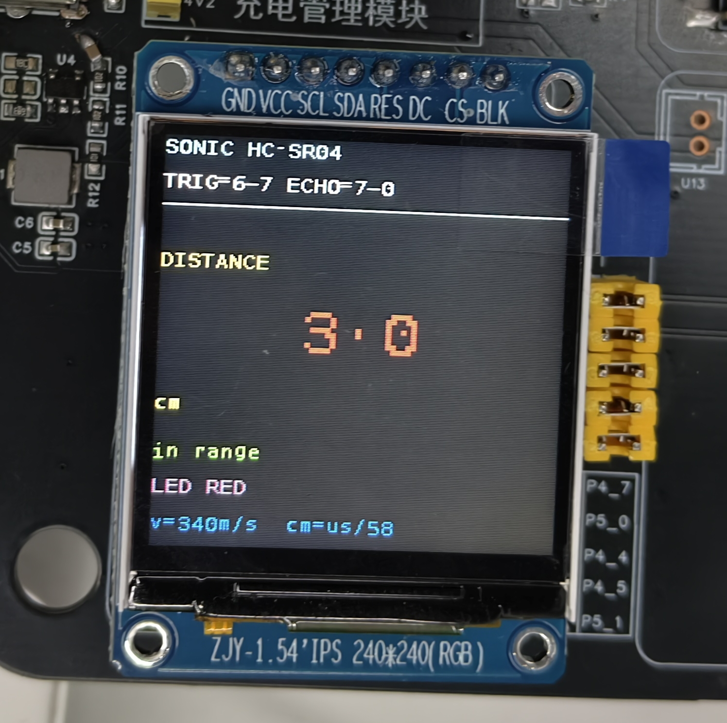
Ultrasonic ranging display

RGB colors at different distances:

Distance rangeRGB colorTFT displayDescription
< 0 cmBlueBLUE - no echoOut of range or no echo
0~20 cmRedRED - dangerVery close, warning
20~50 cmYellowYELLOW - cautionClose, attention
≥ 50 cmGreenGREEN - safeSafe distance

Fixed and variable parts

  • Fixed parts: the display format and layout (fixed by the code)
  • Variable parts: the distance value and RGB color status (updated on every refresh)

4 RGB Parking-Sensor Function

4.1 Color Algorithm

The RGB LED automatically shows different colors based on the distance, like a car parking sensor:

// Distance-to-color thresholds (cm)
#define RGB_NEAR_RED_CM     20.0f    /* < 20 cm shows red */
#define RGB_MID_YELLOW_CM   50.0f    /* < 50 cm shows yellow */
#define RGB_SAFE_GREEN_CM   50.0f    /* ≥ 50 cm shows green */

const char *rgb_by_distance(float d_cm)
{
    if (d < 0.0f) {
        rgb_set(0, 0, 1);                 /* Blue: no echo / out of range */
        return "BLUE";
    }
    if (d < RGB_NEAR_RED_CM) {
        rgb_set(1, 0, 0);                 /* Red: very close */
        return "RED";
    }
    if (d < RGB_MID_YELLOW_CM) {
        rgb_set(1, 1, 0);                 /* Yellow: close */
        return "YELLOW";
    }
    rgb_set(0, 1, 0);                     /* Green: safe */
    return "GREEN";
}

4.2 RGB Pin Configuration

The RGB LED uses three GPIOs to control the red, green, and blue channels:

// RGB GPIO handle structures
static gpio_handle_t g_r = {
    .chip_path      = "/dev/gpiochip6",
    .line_offset    = 6,                 // GPIO6_6 = R
    .gpio_mode      = GPIOHANDLE_REQUEST_OUTPUT,
    .default_value  = 0,
    .consumer_label = "rgb-r",
};

static gpio_handle_t g_g = {
    .chip_path      = "/dev/gpiochip6",
    .line_offset    = 5,                 // GPIO6_5 = G
    .gpio_mode      = GPIOHANDLE_REQUEST_OUTPUT,
    .default_value  = 0,
    .consumer_label = "rgb-g",
};

static gpio_handle_t g_b = {
    .chip_path      = "/dev/gpiochip5",
    .line_offset    = 3,                 // GPIO5_3 = B
    .gpio_mode      = GPIOHANDLE_REQUEST_OUTPUT,
    .default_value  = 0,
    .consumer_label = "rgb-b",
};

4.3 Color Combination Logic

Color combinations of the common-cathode RGB LED:

RGBResulting colorHex
000Off0x000000
100Red0xFF0000
010Green0x00FF00
001Blue0x0000FF
110Yellow0xFFFF00
101Purple0xFF00FF
011Cyan0x00FFFF
111White0xFFFFFF

5 Ranging Principles

5.1 Ultrasonic Ranging Principle

The HC-SR04 ultrasonic ranging works on the pulse-echo principle:

  1. Trigger stage: the TRIG pin outputs a high-level trigger pulse of ≥10 μs
  2. Emission stage: the module emits 8 pulses of 40 kHz ultrasound internally (8 pulses, about 40 μs in total)
  3. Receive stage: the ECHO pin goes high, indicating the sound wave has been sent
  4. Echo stage: after the echo reflected by the obstacle arrives, the ECHO pin goes low
  5. Calculation stage: measure the duration of the ECHO high level and compute the distance

Distance formula:

Distance (cm) = ECHO high-level time (μs) / 58

Note: the speed of sound is about 340 m/s, so a 1 cm round trip takes about 58 μs.

5.2 Pulse-Width Measurement

Pulse-width measurement using a high-precision clock:

// Measure the ECHO pulse width
struct timespec start, current;
int pulse_width_us;

// Wait for ECHO to go high
while (gpio_get_value(ECHO_GPIO) == 0) {
    clock_gettime(CLOCK_MONOTONIC_RAW, &start);
    if (is_timeout(start, 30000)) return -1;  // 30 ms timeout protection
}

// Record the start time
clock_gettime(CLOCK_MONOTONIC_RAW, &start);

// Wait for ECHO to go low
while (gpio_get_value(ECHO_GPIO) == 1) {
    clock_gettime(CLOCK_MONOTONIC_RAW, &current);
    if (is_timeout(start, 30000)) return -1;  // 30 ms timeout protection
}

// Compute the pulse width (microseconds)
pulse_width_us = (current.tv_sec - start.tv_sec) * 1000000 +
                   (current.tv_nsec - start.tv_nsec) / 1000;

// Compute the distance
float distance_cm = pulse_width_us / 58.0f;

5.3 Timeout Protection

To keep a measurement from getting stuck, a 30 ms timeout is applied:

static int is_timeout(struct timespec start, int timeout_ms)
{
    struct timespec current;
    clock_gettime(CLOCK_MONOTONIC_RAW, &current);

    long elapsed_us = (current.tv_sec - start.tv_sec) * 1000000 +
                     (current.tv_nsec - start.tv_nsec) / 1000;

    return elapsed_us >= (timeout_ms * 1000);
}

// Usage inside a wait loop
while (gpio_get_value(ECHO_GPIO) == 0) {
    clock_gettime(CLOCK_MONOTONIC_RAW, &start);
    if (is_timeout(start, 30000)) {
        return -1;  // 30 ms timeout
    }
}

6 Key Programming Points

6.1 GPIO Input/Output Operations

TRIG trigger pulse:

// Output a 20 μs trigger pulse
gpio_set_value(TRIG_GPIO, 1);  // Pull high
usleep(20);                     // Hold for 20 μs
gpio_set_value(TRIG_GPIO, 0);  // Pull low

ECHO pulse-width reading:

// Read the GPIO input state
int echo_state = gpio_get_value(ECHO_GPIO);

6.2 Multi-GPIO RGB LED Control

Controlling 3 GPIOs simultaneously:

void rgb_set(int r, int g, int b)
{
    gpio_set_value(&g_r, r ? 1 : 0);
    gpio_set_value(&g_g, g ? 1 : 0);
    gpio_set_value(&g_b, b ? 1 : 0);
}

Initializing the RGB GPIOs:

int rgb_init(void)
{
    if (gpio_handle_init(&g_r) < 0) return -1;
    if (gpio_handle_init(&g_g) < 0) return -1;
    if (gpio_handle_init(&g_b) < 0) return -1;

    rgb_off();  // Turn all LEDs off initially
    return 0;
}

6.3 Error Handling and Filtering

Median of multiple measurements:

#define SAMPLE_COUNT 5

float measure_distance_filtered(void)
{
    float samples[SAMPLE_COUNT];

    // Take 5 consecutive measurements
    for (int i = 0; i < SAMPLE_COUNT; i++) {
        samples[i] = sonic_measure_once();
        usleep(50000);  // 50 ms interval
    }

    // Sort and take the median
    qsort(samples, SAMPLE_COUNT, sizeof(float), cmp_float);
    return samples[SAMPLE_COUNT / 2];
}

7 Troubleshooting

ProblemPossible causeSolution
Shows "no echo"No obstacle ahead, too close (<2 cm), ECHO not connected or poorly dividedTest in the 10~50 cm range, check the ECHO connection and divider circuit
Shows "out of range"Obstacle beyond 4 m or sound wave dispersesMove the obstacle closer, ensure a suitable reflecting surface
RGB LED offWrong GPIO config, RGB LED not initializedCheck GPIO6_6/6_5/5_3 config, confirm rgb_init() runs
Wrong RGB colorImproper color algorithm parametersCheck the RGB_NEAR_RED_CM and RGB_MID_YELLOW_CM thresholds
Jumpy valuesUser-space polling jitter, near-distance measurement errorAdd filtering, avoid very close measurements
Program hangsECHO never signals, timeout protection ineffectiveCheck the ultrasonic module supply and connections

Measurement distance tips

For best measurement results:

  • The obstacle area should be ≥ 10 cm × 10 cm
  • Measure within 10 cm ~ 300 cm
  • The obstacle surface should be flat or slightly curved
  • Avoid sound-absorbing materials (e.g. sponge, foam) as obstacles

8 Advanced Features

8.1 Data Filtering

#define FILTER_WINDOW 5

typedef struct {
    float buffer[FILTER_WINDOW];
    int index;
} DistanceFilter;

float filter_add_sample(DistanceFilter *f, float new_value)
{
    f->buffer[f->index] = new_value;
    f->index = (f->index + 1) % FILTER_WINDOW;

    // Sort and take the median
    float temp[FILTER_WINDOW];
    memcpy(temp, f->buffer, sizeof(temp));
    qsort(temp, FILTER_WINDOW, sizeof(float), cmp_float);
    return temp[FILTER_WINDOW / 2];
}

8.2 Multi-Level Parking-Sensor Alerts

typedef enum {
    ALERT_SAFE = 0,      // ≥ 50 cm green
    ALERT_ATTENTION,   // 20~50 cm yellow
    ALERT_DANGER,      // 10~20 cm yellow-red flashing
    ALERT_CRITICAL,    // < 10 cm red flashing
} alert_level_t;

alert_level_t get_alert_level(float distance)
{
    if (distance < 10.0f) return ALERT_CRITICAL;
    if (distance < 20.0f) return ALERT_DANGER;
    if (distance < 50.0f) return ALERT_ATTENTION;
    return ALERT_SAFE;
}

8.3 Multiple Ultrasonic Sensors

Multi-sensor data fusion:

#define SONIC_SENSOR_COUNT 3

typedef struct {
    int trig_gpio;
    int echo_gpio;
    float position_offset;
} SonicSensor;

float multi_sonic_measure(SonicSensor *sensors, int count)
{
    float distances[SONIC_SENSOR_COUNT];

    for (int i = 0; i < count; i++) {
        distances[i] = sonic_measure_sensor(sensors[i]);
    }

    // Take the minimum as the final distance
    float min_distance = distances[0];
    for (int i = 1; i < count; i++) {
        if (distances[i] < min_distance) {
            min_distance = distances[i];
        }
    }

    return min_distance;
}

9 References

  • GPIO Interface in Detail
  • Buzzer Application
  • TFT Display Application
  • Development Environment Setup
Edit this page on GitHub
Prev
08 - SHT20 Temperature & Humidity Application
Next
10 - SpO2 Sensor Application