
08 - SHT20 Temperature & Humidity Application
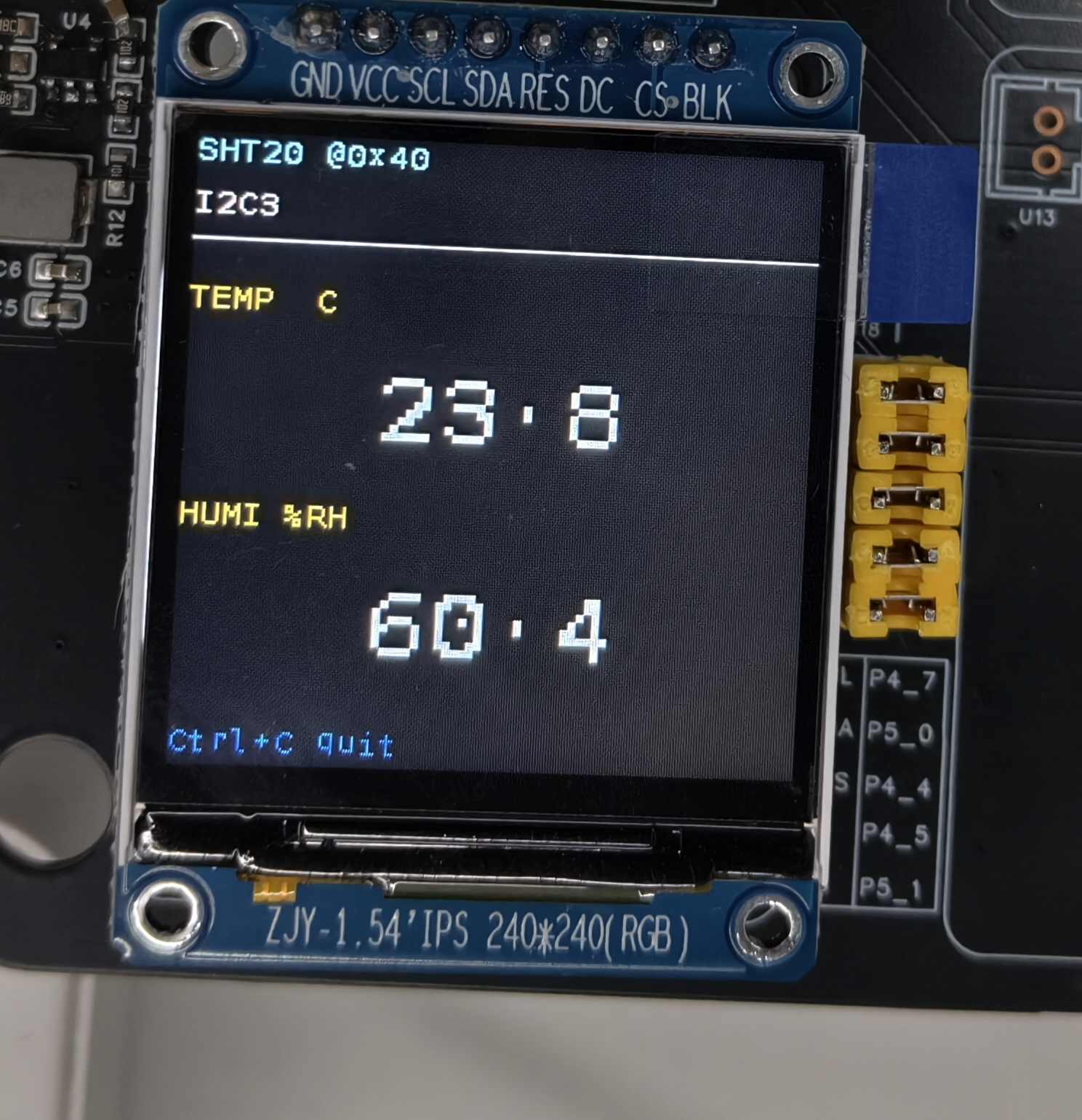
This chapter describes the SHT20 temperature & humidity sensor application example — sht20_display — on the Pico-G1 expansion board. The application demonstrates how to read temperature and humidity data from an SHT20 sensor over the I2C interface and display the ambient information in real time on a TFT screen. It is a fundamental example for learning I2C environmental monitoring sensors.
The application source code is located in the SDK directory source/app/08_sht20_display/ and provides a complete implementation of reading an I2C temperature & humidity sensor.
1 Application Overview
1.1 Features
- I2C temperature & humidity reading: reads SHT20 temperature and humidity data over the I2C interface
- Environmental monitoring: displays the current ambient temperature and humidity in real time
- High-precision display: supports 0.1°C temperature and 1% humidity resolution
- Multi-chip compatibility: supports SHT20/SI7021/HTU21 and other compatible chips
1.2 Technical Specifications
| Parameter | Value |
|---|---|
I2C interface | I2C3 (/dev/i2c-3) |
Slave address | 0x40 |
Temperature range | -40~125°C |
Humidity range | 0~100% RH |
Temperature accuracy | ±0.3°C |
Humidity accuracy | ±2% RH |
Refresh interval | 2 s (configurable) |
1.3 Test Case List
| index | Name | Test command | Expected result (success) | Possible causes of failure |
|---|---|---|---|---|
| 1 | Basic reading | ./sht20_display | TFT shows temperature/humidity, console prints data | I2C connection failed, wrong address |
| 2 | Temperature change | Warm the sensor with a hand | Temperature rises by 2~5°C | Slow sensor response, poor contact |
| 3 | Humidity change | Breathe on the sensor | Humidity rises by 10~20% | Contaminated sensor, humidity response lag |
1.4 Directory Structure
source/app/08_sht20_display/
├── Makefile              # Build script
├── main.c                # Main program
├── sht20.c               # SHT20 driver implementation
├── sht20.h               # SHT20 driver header
├── i2c_hal.c             # I2C HAL layer implementation
├── i2c_hal.h             # I2C HAL layer header
├── spi_hal.c             # SPI HAL layer implementation
├── spi_hal.h             # SPI HAL layer header
├── st7789.c              # ST7789 driver implementation
├── st7789.h              # ST7789 driver header
├── font8x16.h            # 8×16 ASCII bitmap font
└── README.md             # Documentation
2 Hardware Connection
2.1 Pin Definitions
| Signal | On-board GPIO | Controller / node | Description |
|---|---|---|---|
| SCL | GPIO4_1 | I2C3 → /dev/i2c-3 | Shares the I2C3 bus with OLED/MPU6050 |
| SDA | GPIO4_2 | I2C3 → /dev/i2c-3 | Shared bus |
| VCC | 3.3V | — | SHT20 supply 2.1~3.6V |
| GND | GND | — | Ground |
2.2 Hardware Circuit
SHT20 wiring diagram:
     Pico-G1                   SHT20 Module
  ┌───────────┐              ┌──────────────┐
  │           │              │              │
  │ GPIO4_1 ──┼────── SCL ───┤ SCL          │
  │           │              │              │
  │ GPIO4_2 ──┼────── SDA ───┤ SDA          │
  │           │              │              │
  │    3.3V ───┼─────────────┤ VCC          │
  │           │              │              │
  │     GND ───┼─────────────┤ GND          │
  └───────────┘              └──────────────┘
Chip compatibility
SHT20, SI7021, and HTU21 share compatible I2C addresses and commands, so they can be used interchangeably.
3 Build and Deployment
3.1 Build the Application
export PATH=$PATH:<SDK>/tools/linux/toolchains/arm-gcc12.2.0-linux-uclibceabi/bin
cd <SDK>/source/app/08_sht20_display
make
3.2 Run the Application
scp sht20_display root@<board_ip>:/usr/bin/
ssh root@<board_ip> '/usr/bin/sht20_display'
3.3 Expected Output
Console output
/mnt # ./sht20_display
[sht20] pad 复用:I2C3(4_1/4_2) -> func2
[sht20] pad 0x100C0010 -> 0x00001002
[sht20] pad 0x100C0014 -> 0x00001002
[sht20] 初始化 SPI 屏(/dev/spidev2.0)...
[spi] pad 0x100C0028 -> 0x00001004
[spi] pad 0x100C002C -> 0x00001004
[spi] pad 0x100C0030 -> 0x00001000
[spi] pad 0x100C0020 -> 0x00001005
[spi] pad 0x100C001C -> 0x00001005
[spi] opening /dev/spidev2.0 ...
[spi] spidev opened, fd=3
[spi] spidev mode/bits/speed set (MODE3/8b/24MHz)
[spi] chardev request DC  @ /dev/gpiochip4 line 5 ...
[spi] chardev request RES @ /dev/gpiochip4 line 4 ...
[spi] chardev request CS  @ /dev/gpiochip5 line 1 ...
[spi] chardev-verify: DC=0(expect0) RES=1(expect1) CS=1(expect1)  ==> OK(chardev 真驱动了引脚)
[spi] spi_hal_init done
[tft] init: SLPOUT
[tft] init: SLPOUT +120ms ok
[tft] init: config cmds ok
[tft] init: DISPON
[tft] init: DISPON ok
[tft] init: clear-flush start
[tft] flush #1 start
[tft] flush #1 done
[tft] init: clear-flush done
[sht20] 初始化 SHT20(/dev/i2c-3 addr 0x40)...
[sht20] @ /dev/i2c-3 addr 0x40 就绪 (user_reg=0x3A)
[sht20] 采集中,每 2s 刷新,Ctrl+C 退出。
[sht20] T=23.7 C  RH=60.5 %
TFT screen display
4 SHT20 Temperature & Humidity Principles
4.1 I2C Communication Protocol
The SHT20 communicates using the standard I2C protocol:
- Slave address: 0x40 (write address 0x80, read address 0x81)
- Supported speeds: standard mode (100 kHz) and fast mode (400 kHz)
- Data format: 16-bit measurement data + 8-bit CRC
4.2 Measurement Commands
| Command name | Command code | Description |
|---|---|---|
| Temperature (hold) | 0xE3 | Hold Master mode |
| Temperature (no hold) | 0xF3 | No Hold Master mode |
| Humidity (hold) | 0xE5 | Hold Master mode |
| Humidity (no hold) | 0xF5 | No Hold Master mode |
4.3 Data Conversion Formulas
Temperature calculation:
float sht20_convert_temperature(uint16_t raw_temp)
{
    return -46.85f + 175.72f * (raw_temp / 65536.0f);
}
Humidity calculation:
float sht20_convert_humidity(uint16_t raw_humi)
{
    return -6.0f + 125.0f * (raw_humi / 65536.0f);
}
5 Key Programming Points
5.1 I2C Device Operations
Opening the I2C device:
int i2c_open(const char *i2c_bus, uint8_t device_addr)
{
    int fd = open(i2c_bus, O_RDWR);
    if (fd < 0) return -1;

    if (ioctl(fd, I2C_SLAVE, device_addr) < 0) {
        close(fd);
        return -1;
    }

    return fd;
}
5.2 Temperature & Humidity Reading
Reading temperature data:
float sht20_read_temperature(int i2c_fd)
{
    uint8_t cmd = 0xE3;  // Temperature hold command
    uint8_t data[3];

    i2c_write_byte(i2c_fd, SHT20_ADDR, &cmd, 1);
    usleep(85000);  // Wait for the measurement to finish

    i2c_read_bytes(i2c_fd, SHT20_ADDR, data, 3);

    uint16_t raw_temp = (data[0] << 8) | data[1];
    return sht20_convert_temperature(raw_temp);
}
Reading humidity data:
float sht20_read_humidity(int i2c_fd)
{
    uint8_t cmd = 0xE5;  // Humidity hold command
    uint8_t data[3];

    i2c_write_byte(i2c_fd, SHT20_ADDR, &cmd, 1);
    usleep(30000);  // Wait for the measurement to finish

    i2c_read_bytes(i2c_fd, SHT20_ADDR, data, 3);

    uint16_t raw_humi = (data[0] << 8) | data[1];
    return sht20_convert_humidity(raw_humi);
}
5.3 CRC Check
CRC8 algorithm:
bool sht20_check_crc(const uint8_t *data, uint8_t len, uint8_t checksum)
{
    uint8_t crc = 0xFF;

    for (uint8_t i = 0; i < len; i++) {
        crc ^= data[i];
        for (uint8_t bit = 8; bit > 0; bit--) {
            if (crc & 0x80) {
                crc = (crc << 1) ^ 0x131;
            } else {
                crc = crc << 1;
            }
        }
    }

    return (crc == checksum);
}
6 Troubleshooting
| Problem | Possible cause | Solution |
|---|---|---|
| Reading failed | I2C connection failed, wrong address | Check the wiring, confirm address 0x40, use i2cdetect -y 3 to check visibility |
| Abnormal temperature | Damaged sensor, poor contact | Reconnect the sensor, replace the sensor |
| Humidity stuck | Calibration issue, contaminated sensor | Recalibrate the sensor, clean the sensor |
| CRC errors | I2C interference, electrical noise | Check the I2C pull-up resistors, add filter capacitors |
| Jumpy values | Rapid environment changes, unstable airflow | Stabilize the measurement environment, apply data filtering |
Measurement tips
For best measurement results:
- Warm-up time: let the sensor warm up for 1~2 minutes after power-on before measuring
- Placement: avoid direct sunlight, air-conditioner outlets, and heat sources
- Regular calibration: calibrate every 6 months against a standard temperature/humidity source
7 Advanced Features
7.1 Data Filtering
Moving-average filter:
#define FILTER_WINDOW 5

void sht20_filter_add(float temp, float humi)
{
    static float temp_buf[FILTER_WINDOW] = {0};
    static float humi_buf[FILTER_WINDOW] = {0};
    static int index = 0;

    temp_buf[index] = temp;
    humi_buf[index] = humi;
    index = (index + 1) % FILTER_WINDOW;

    // Compute the averages
    float temp_avg = 0, humi_avg = 0;
    for (int i = 0; i < FILTER_WINDOW; i++) {
        temp_avg += temp_buf[i];
        humi_avg += humi_buf[i];
    }
    temp_avg /= FILTER_WINDOW;
    humi_avg /= FILTER_WINDOW;

    printf("[SHT20] 温度: %.1f°C 湿度: %.1f%% (滤波后)\n", temp_avg, humi_avg);
}
7.2 Temperature & Humidity Alarms
Alarm detection logic:
typedef struct {
    float temp_warning_high;   // High temperature warning threshold
    float temp_warning_low;    // Low temperature warning threshold
    float humi_warning_high;   // High humidity warning threshold
    float humi_warning_low;    // Low humidity warning threshold
} sht20_alarm_threshold_t;

sht20_alarm_threshold_t g_alarm_threshold = {
    .temp_warning_high = 35.0f,
    .temp_warning_low = 15.0f,
    .humi_warning_high = 70.0f,
    .humi_warning_low = 30.0f,
};

void sht20_check_alarm(float temp, float humi)
{
    if (temp > g_alarm_threshold.temp_warning_high) {
        printf("[SHT20] 温度过高警告: %.2f°C\n", temp);
    }
    if (temp < g_alarm_threshold.temp_warning_low) {
        printf("[SHT20] 温度过低警告: %.2f°C\n", temp);
    }
    if (humi > g_alarm_threshold.humi_warning_high) {
        printf("[SHT20] 湿度过高警告: %.2f%%\n", humi);
    }
    if (humi < g_alarm_threshold.humi_warning_low) {
        printf("[SHT20] 湿度过低警告: %.2f%%\n", humi);
    }
}